Arduino UNO R4 - 10 Segment LED Bar Graph
Or you can buy the following kits:
| 1 | × | DIYables STEM V4 IoT Starter Kit (Arduino included) | |
| 1 | × | DIYables Sensor Kit (18 sensors/displays) |
Additionally, some of these links are for products from our own brand, DIYables .

In this guide, we will learn how to use the 10 Segment LED Bar Graph with the Arduino UNO R4. In detail, we will learn:
- How to connect the 10 Segment LED Bar Graph to the Arduino UNO R4.
- How to write a program for the Arduino UNO R4 to control the LED bar display.
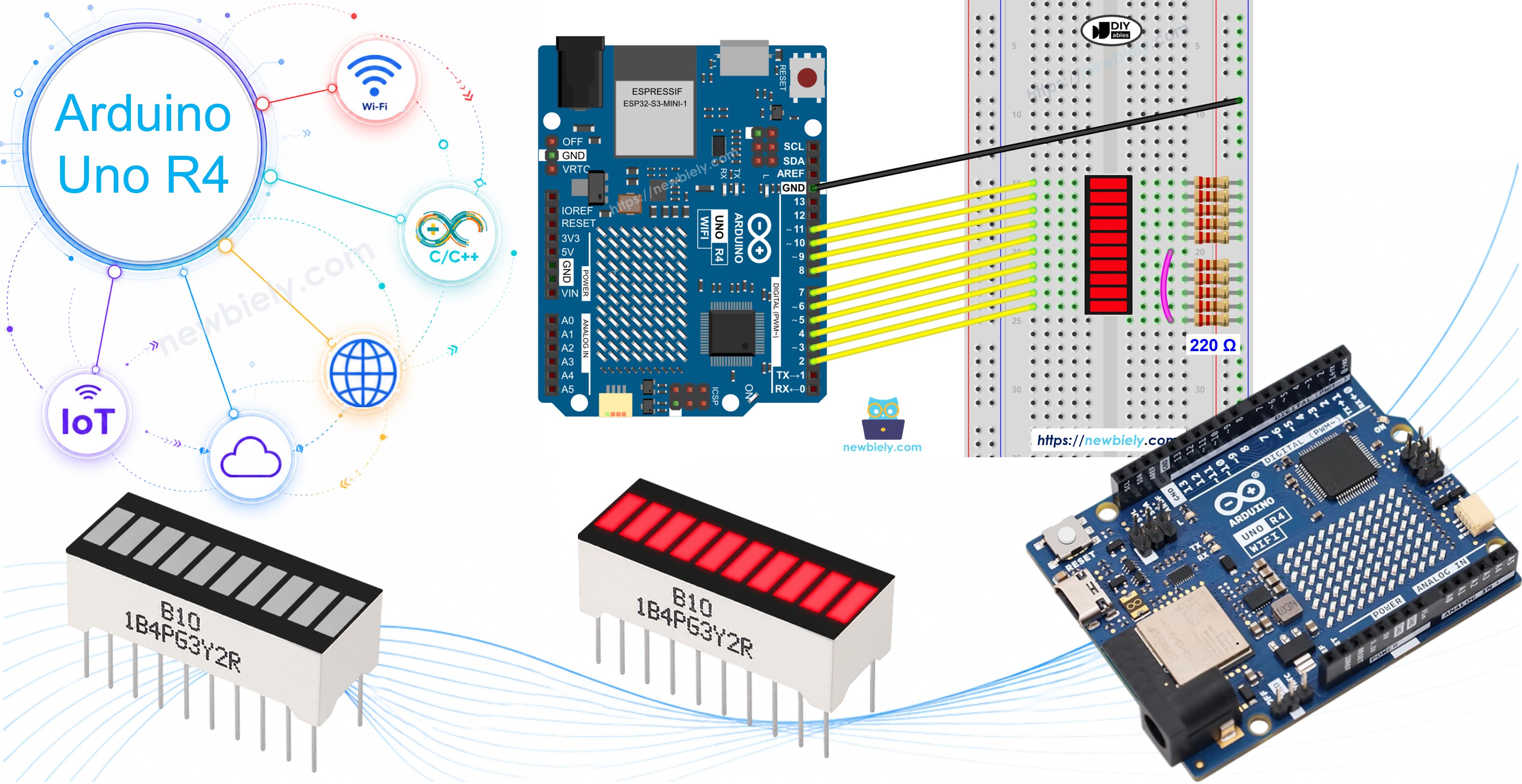
Overview of 10 Segment LED Bar Graph
The 10 Segment LED Bar Graph is a compact display component with ten individual LED segments arranged in a row. Each segment has its own anode and cathode pin, allowing independent control. It is commonly used to visualize levels, progress, or signal strength.
| 10 Segment LED Bar Graph | |
|---|---|
| Number of Segments | 10 |
| LED Color | Bright red |
| Forward Voltage | ~2V per segment |
| Forward Current | 20mA max per segment |
| Resistor Required | 220Ω per segment |
Pinout
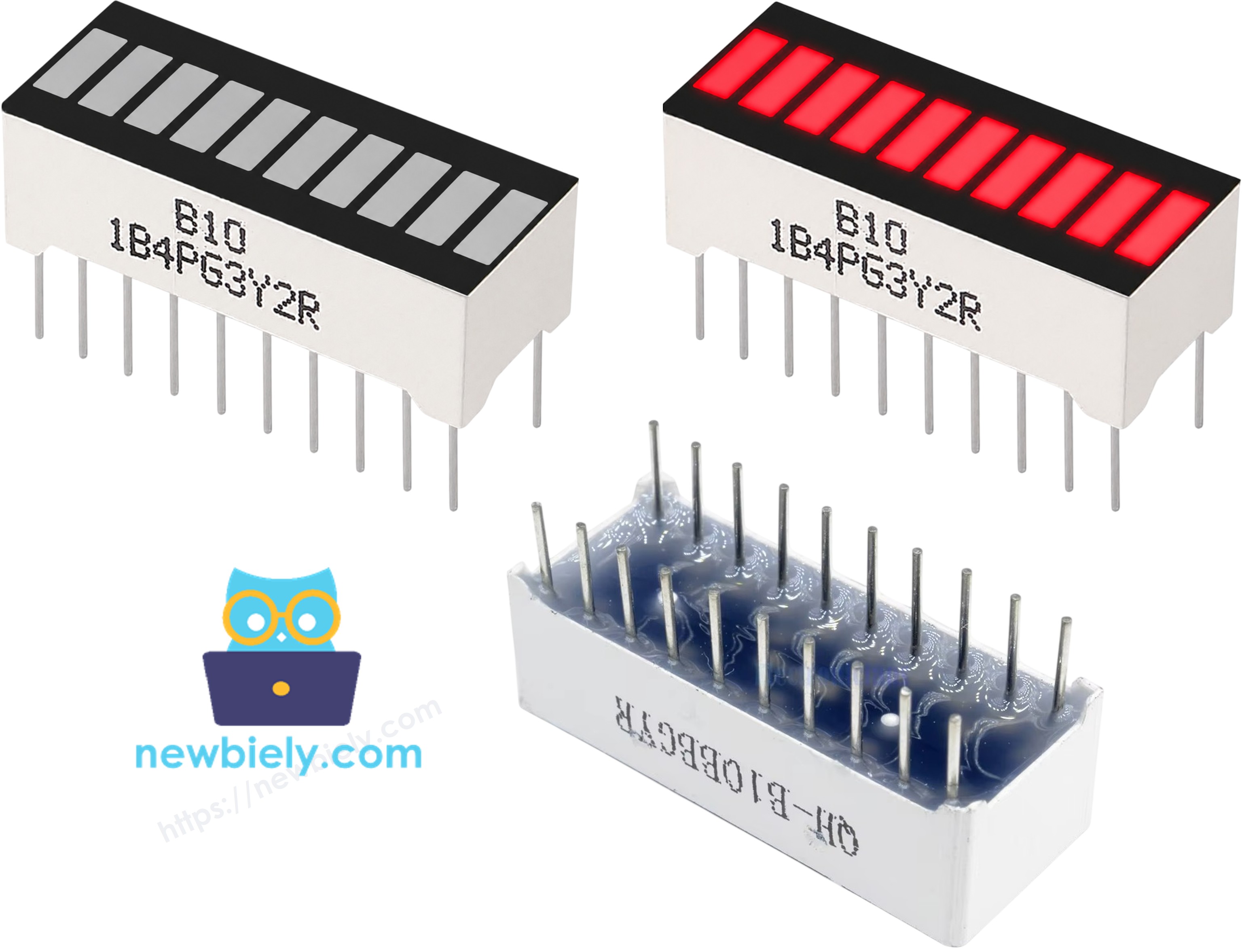
The 10 Segment LED Bar Graph has 20 pins — 10 anodes and 10 cathodes:
- Anode pins (A1–A10): connect to GPIO pins via 220Ω resistors
- Cathode pins (K1–K10): connect to GND
Wiring Diagram between 10 Segment LED Bar Graph and Arduino UNO R4
Connect each anode pin of the LED bar graph to an Arduino UNO R4 GPIO pin through a 220Ω resistor, and connect all cathode pins to GND.
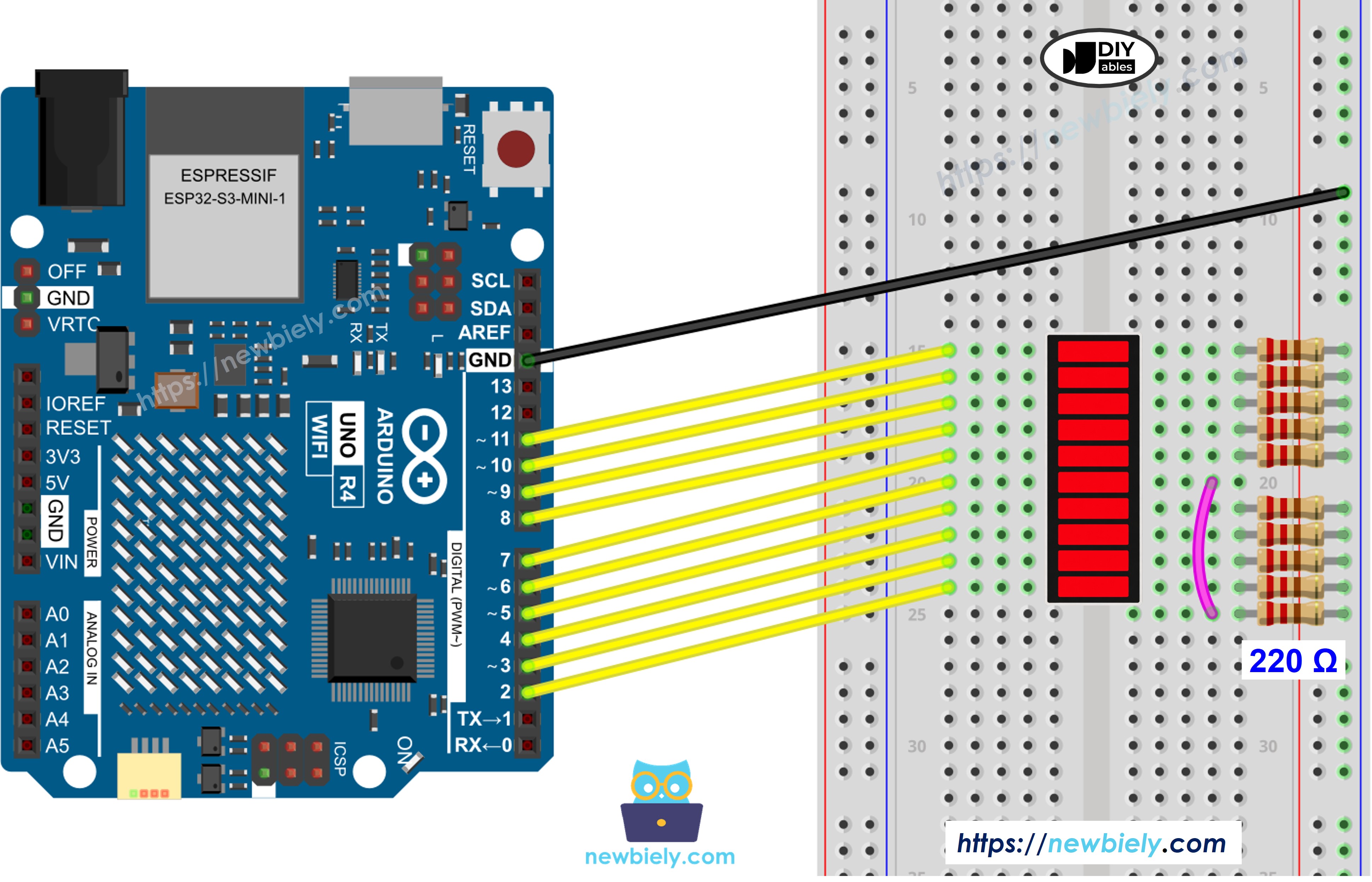
This image is created using Fritzing. Click to enlarge image
See The best way to supply power to the Arduino Uno R4 and other components.
| LED Bar Graph | Arduino UNO R4 Pin |
|---|---|
| A1 (Anode 1) | Pin 2 (via 220Ω) |
| A2 (Anode 2) | Pin 3 (via 220Ω) |
| A3 (Anode 3) | Pin 4 (via 220Ω) |
| A4 (Anode 4) | Pin 5 (via 220Ω) |
| A5 (Anode 5) | Pin 6 (via 220Ω) |
| A6 (Anode 6) | Pin 7 (via 220Ω) |
| A7 (Anode 7) | Pin 8 (via 220Ω) |
| A8 (Anode 8) | Pin 9 (via 220Ω) |
| A9 (Anode 9) | Pin 10 (via 220Ω) |
| A10 (Anode 10) | Pin 11 (via 220Ω) |
| K1–K10 (Cathodes) | GND |
How To Program Arduino UNO R4 for 10 Segment LED Bar Graph
- No library needed for this project.
- Define the anode pin array: const int ledPins[10] = {2, 3, 4, 5, 6, 7, 8, 9, 10, 11};
- Set each pin as an output.
- Turn on segment i: digitalWrite(ledPins[i], HIGH);
- Turn off segment i: digitalWrite(ledPins[i], LOW);
Arduino UNO R4 Code - 10 Segment LED Bar Graph
Detailed Instructions
Follow these instructions step by step:
- Open the Arduino IDE. If you do not have it installed, see the Arduino UNO R4 getting started guide.
- Connect the 10 Segment LED Bar Graph to the Arduino UNO R4 according to the wiring diagram.
- Connect the Arduino UNO R4 to the computer using a USB Type-C cable.
- Open the Arduino IDE, select the appropriate Arduino UNO R4 board (e.g., Arduino UNO R4 WiFi or Arduino UNO R4 Minima) and COM port.
- Copy the code above and paste it into the Arduino IDE.
- Click the Upload button to upload the code to the Arduino UNO R4.
- Open the Serial Monitor.
- Observe the LED bar graph filling up segment by segment, then emptying back down, and repeating.