
ESP32 UNO - NTC Thermistor Temperature Sensor
A fish tank, a home-brew bucket, a freezer in the garage: each of them needs a temperature sensor that does not mind getting wet. The DIYables 10K NTC thermistor probe is made for that. Its tip is a sealed steel tube with a tiny heat-sensitive resistor inside. Add the 10K resistor that comes in the same bag, connect three points on the ESP32 Uno form board, and a short sketch prints the temperature in °C and °F. No library is needed.
Here is the plan:
- Look inside the steel probe and see why its two wires have no + or − side
- Build a small voltage divider on the 3.3V and A2 (GPIO35) pins
- Upload one sketch that turns millivolts into ohms, then ohms into °C and °F
- Check the readings with a bowl of warm water
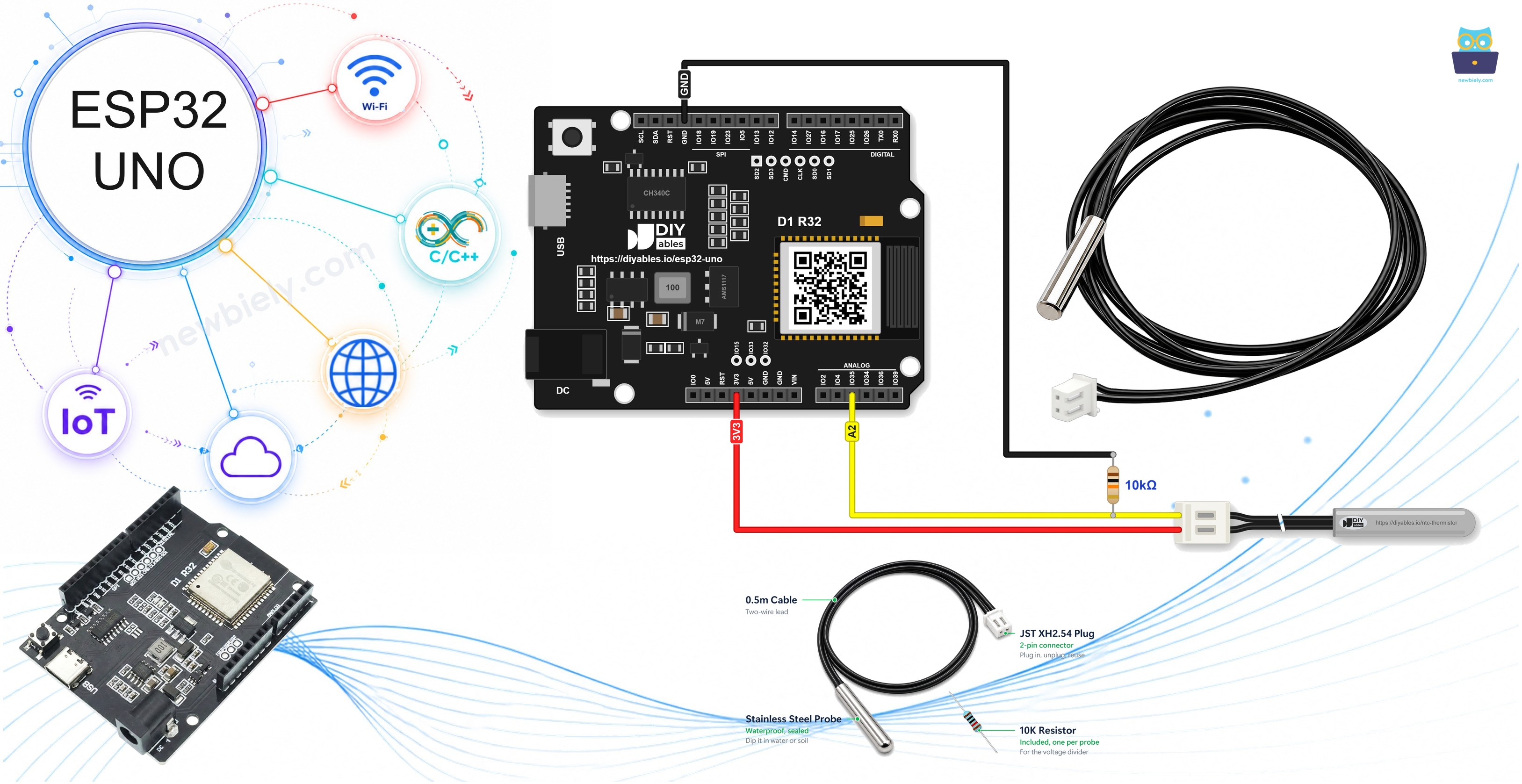
Components You Need
Or you can buy the following kits:
| 1 | × | DIYables Sensor Kit (18 sensors/displays) |
Additionally, some of these links are for products from our own brand, DIYables .
Good to know: the probe kit holds five probes and five matching 10K resistors, so you do not need to buy a resistor. The breadboard only makes it easy to join the resistor to the wires.
The 10K NTC Thermistor Probe
Read this part once, and every number in the Serial Monitor will make sense.
The probe looks like a short steel pencil on a black cable. The thermistor sits inside the 5mm x 25mm stainless-steel tip, sealed against water. The 0.5m cable carries two wires and ends in a white JST XH2.54 plug with two holes. There is no module board. You push two male jumper wires into the holes of the plug, and the probe is ready. Both wires are the same: a thermistor is a resistor, so it has no + or − side.
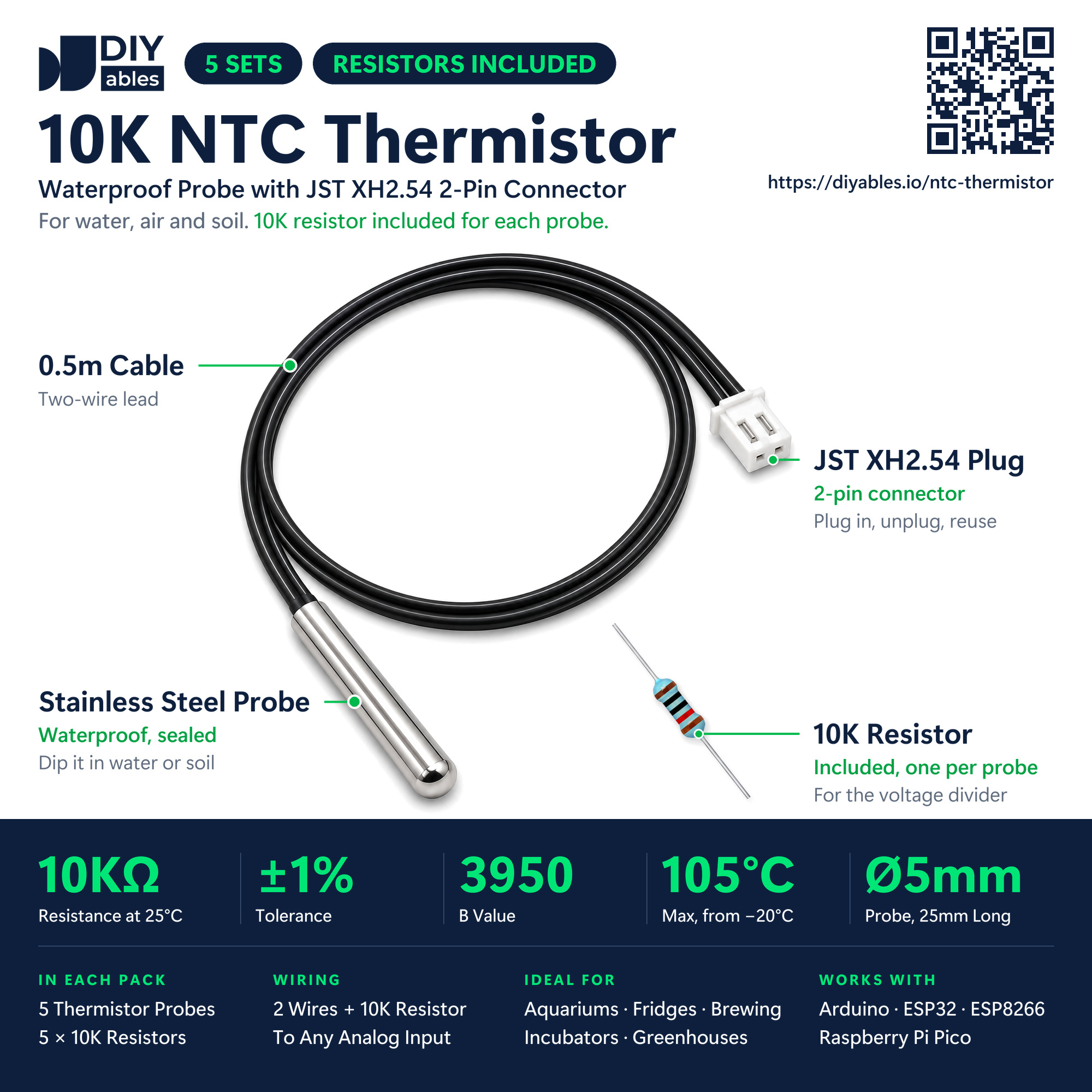
| Item | Value |
|---|---|
| Thermistor | NTC, 10K at 25°C, ±1% |
| B value | 3950 |
| Temperature range | -20°C to 105°C |
| Probe | Stainless steel, waterproof, 5mm x 25mm, round tip |
| Cable | 0.5m, 2 wires, no polarity |
| Connector | JST XH2.54 2-pin plug |
| In the kit | 5 probes and 5 matching 10K resistors |
How It Senses Heat
The thermistor in the tip is very sensitive to heat: a few degrees are enough to change its ohms in a way you can see. The sketch finds those ohms and converts them to degrees. NTC stands for Negative Temperature Coefficient, which simply means the ohms go down as the probe warms up.
The ESP32 Uno cannot measure ohms, only volts. That is the job of the 10K resistor from the kit. Together with the thermistor, it forms a voltage divider. The thermistor sits between 3.3V and A2, and the resistor sits between A2 and GND. A warmer probe has fewer ohms, so more of the 3.3V reaches A2.
| Probe Temperature | Thermistor Resistance | Voltage on A2 |
|---|---|---|
| -10°C | 58,246 ohms | 0.48V |
| 15°C | 15,837 ohms | 1.28V |
| 25°C | 10,000 ohms | 1.65V |
| 40°C | 5,301 ohms | 2.16V |
| 70°C | 1,760 ohms | 2.81V |
From Ohms to Degrees
The sketch does the math in two steps.
Step 1, millivolts to ohms: R = 10000 × (3300 − mV) / mV
Step 2, ohms to kelvin (the B formula): 1/T = 1/T0 + (1/B) × ln(R/R0)
Here T0 is 298.15 K (that is 25°C), R0 is 10000 ohms and B is 3950. The result T is in kelvin, so °C = T − 273.15. You may also meet the Steinhart-Hart equation. It uses three coefficients and is a little more exact, yet the one-number B formula does the job well for this probe.
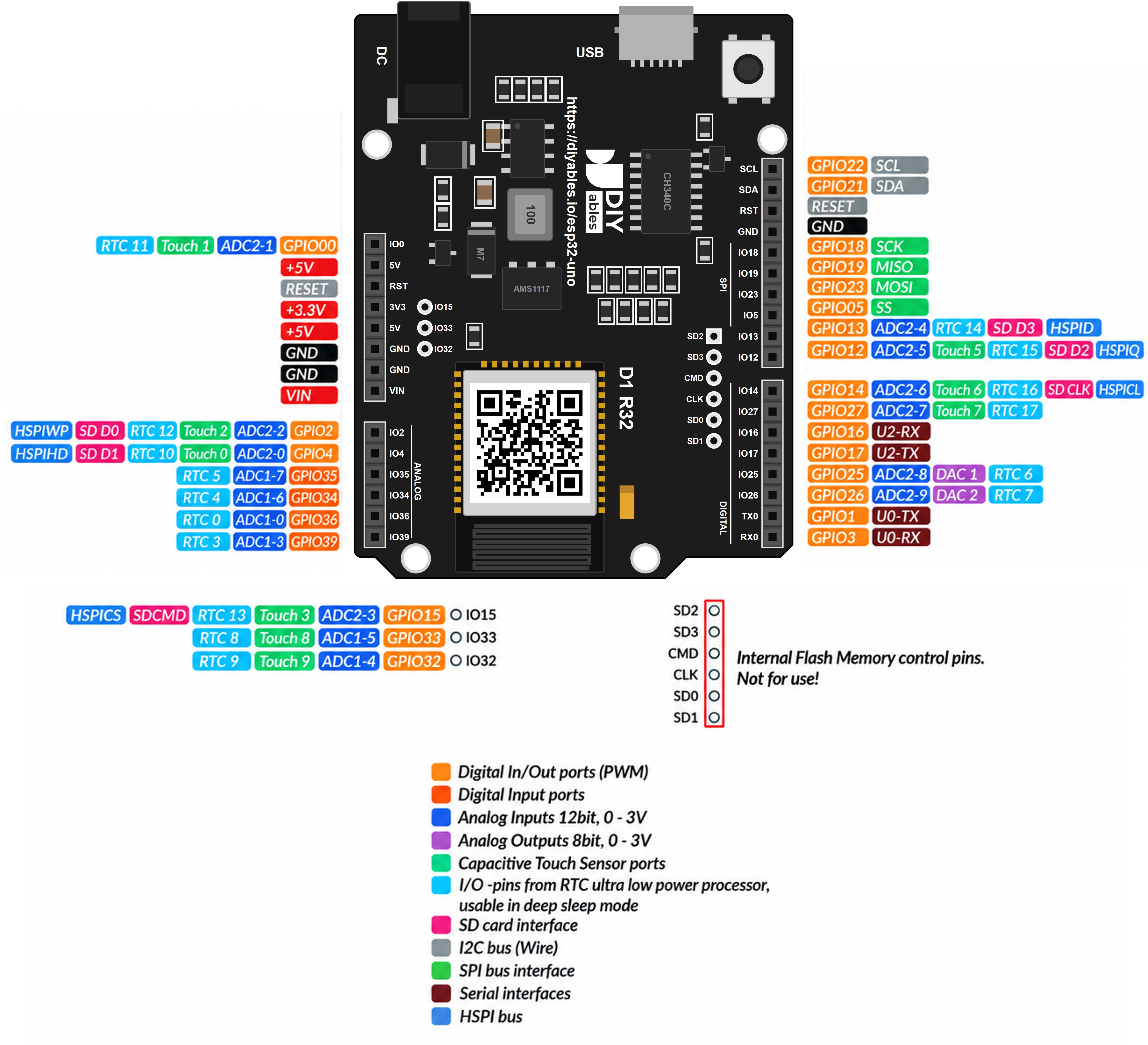
ESP32 Uno Pinout
The probe uses the hole printed A2, yet the sketch calls it 35. That is because A2 is wired to GPIO35 of the ESP32 chip. The map below lists the GPIO number behind every Uno label.
How to Connect
The whole circuit has three points: 3.3V, A2 and GND. Push one male jumper wire into each hole of the white plug. Then the 10K resistor bridges A2 and GND. The drawing shows the resistor legs joined straight to the wires. On your desk, a small breadboard makes that joint easy, or you can twist each leg around a wire end and solder it.
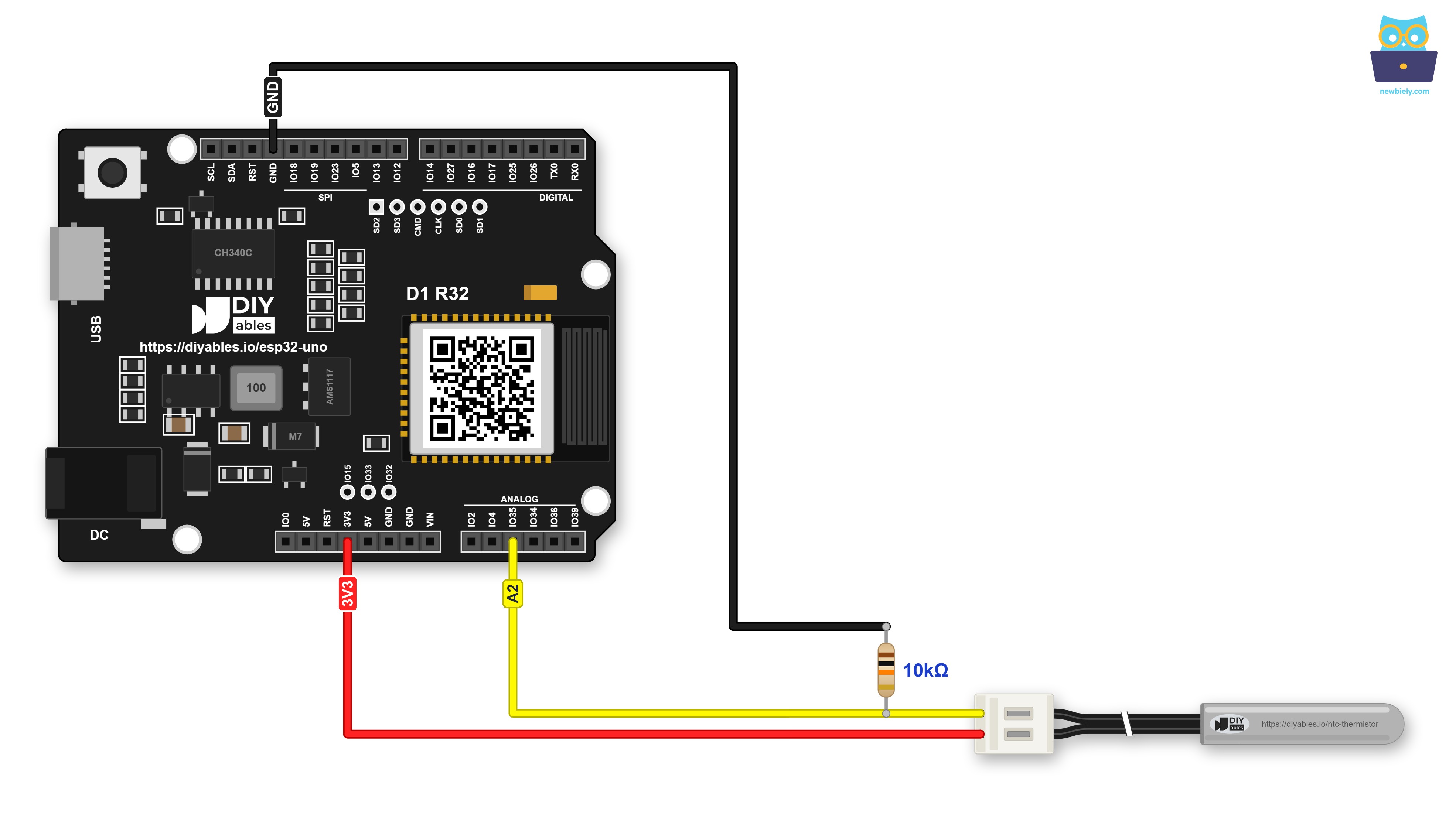
This image is created using Fritzing. Click to enlarge image
| Circuit Point | ESP32 Uno Pin |
|---|---|
| Probe wire (either one) | 3.3V |
| Other probe wire | A2 (GPIO35) |
| 10K resistor, first leg | A2 (GPIO35) |
| 10K resistor, second leg | GND |
For a project that lasts, screw terminals hold the wires better than jumper wires. Try a Screw Shield V2 or a Proto Screw Terminal Block Shield: it sits on the ESP32 Uno, and each pin gets its own screw terminal. Each wire goes to the screw terminal of the same pin, as in the image below.
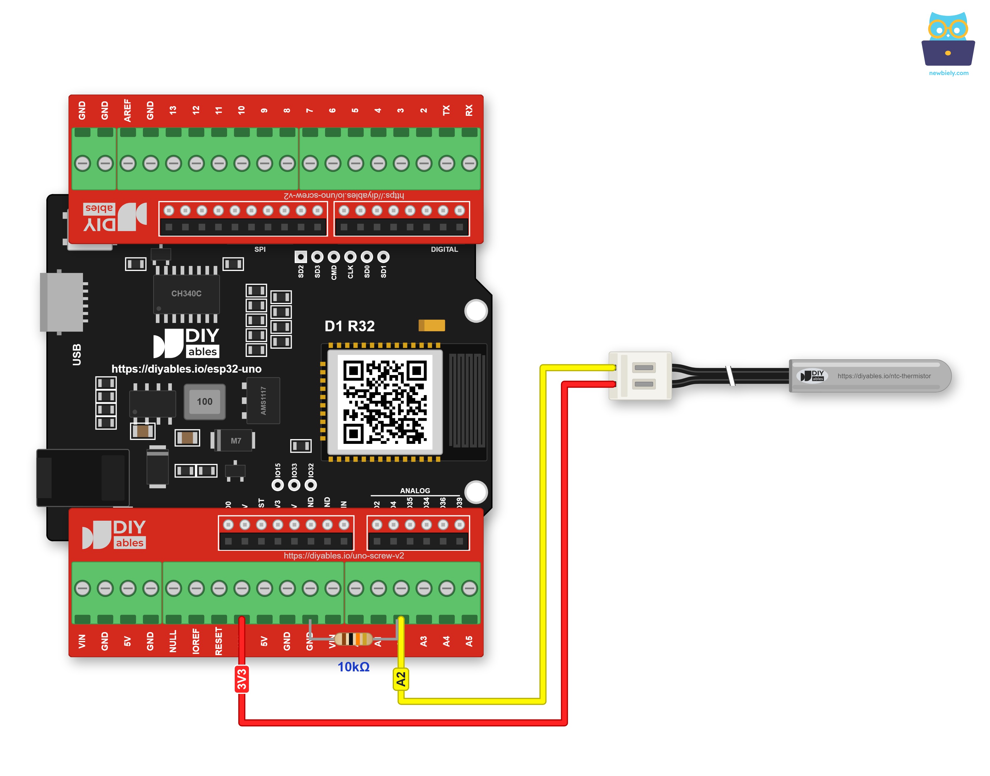
This image is created using Fritzing. Click to enlarge image
Here the 10K resistor goes directly into the screw terminals as well: one leg in GND, the other in A2 together with the probe wire. A screw terminal clamps both at once.
WARNING
Feed the probe from the 3.3V pin, never from 5V. A hot probe has few ohms, so A2 gets close to the supply voltage. From 5V, A2 would pass the 3.3V limit of the ESP32 pins at only about 41°C. The code also counts on 3300 mV at the top of the divider.
Good to know: the probe sits on A2 (GPIO35), not on A0 like many other analog pages for this board. A2 is an ADC1 pin, so it keeps reading when you add WiFi later, and GPIO35 is an input-only pin, which is all a sensor needs. A0 is GPIO2: an ADC2 pin that stops working while WiFi is on, and also a boot strapping pin. The divider would hold GPIO2 at about 1.6V, and that can make an upload fail.
ESP32 Uno Code - Thermistor Temperature in °C and °F
The sketch reads A2 sixteen times, 5 ms apart, and uses the average. It asks for calibrated millivolts with analogReadMilliVolts(), not for a raw count out of 4095. Why? The ESP32 ADC is not a straight line near its two ends, and its top is about 3.1V, not 3.3V. A simple "raw / 4095" ratio would be a few degrees off. Before any math, two checks catch a missing probe and a short, so you see a clear message and never inf or nan.
Upload and Test
- New to the ESP32 Uno? Follow ESP32 Uno - Getting Started to add the ESP32 core to Arduino IDE.
- Wire the probe and the resistor as in the table above.
- Connect the board to your computer with the USB Type-C cable.
- Choose the board in Arduino IDE: ESP32 Dev Module and the CH340 COM port.
- Paste the sketch and press Upload.
- Open the Serial Monitor at 9600 baud.
- Let the probe lie on the desk for ten seconds. Then put the steel tip into a bowl of warm tap water, and keep the plug and the resistor dry. Each line shows the whole chain, from millivolts to ohms to degrees:
- Pro tip: pull the white plug off the jumper wires for a second. The line changes to "No thermistor found", so you know the safety check works.
The first three lines are the room, at about 24°C. In the water, the value climbs over several lines, because the steel tube has to warm up too. Wait until two lines in a row agree before you trust a new reading.
Video Tutorial
Code Explanation
| Code Part | What It Does |
|---|---|
| #define NTC_PIN 35 | The A2 hole is GPIO35, so the code uses 35 |
| analogSetAttenuation(ADC_11db) | Lets A2 read up to about 3.1V, enough for the whole probe range |
| analogReadMilliVolts(NTC_PIN) | Gives the pin voltage in mV, corrected with the calibration stored in the chip |
| for (int i = 0; i < SAMPLES; i++) | Adds 16 readings, so one noisy sample does not move the result |
| raw_avg < 10 | A2 is at the bottom, so no probe pulls it up |
| raw_avg > 4085 | A2 is at the top, so the probe is shorted or the resistor misses GND |
| R_FIXED * (VCC_MV - pin_mv) / pin_mv | Divider math, gives the thermistor resistance in ohms |
| log(r_ntc / R0) / B_VALUE | The B formula, log() is the natural log in Arduino code |
| t_kelvin - 273.15 | Kelvin to °C, then °C × 9 / 5 + 32 gives °F |
ESP32 Uno vs UNO R4 for This Project
The circuit is the same on both boards. Only the supply pin, the analog pin and the math change.
| Item | Arduino UNO R4 | ESP32 Uno |
|---|---|---|
| Probe supply | 5V | 3.3V only |
| Signal pin | A0 | A2 (GPIO35) |
| What the code reads | Raw count, 0 to 1023 | Calibrated millivolts |
| Resistance math | R_FIXED × (1023 / raw − 1) | R_FIXED × (3300 − mV) / mV |
| Extra setup line | none | analogSetAttenuation(ADC_11db) |
The B formula after the resistance step is the same on both boards.
NTC Thermistor, DS18B20 or MAX6675?
All three come as probes, but they fit different jobs.
| Item | 10K NTC Thermistor | DS18B20 Probe | MAX6675 Thermocouple |
|---|---|---|---|
| Signal | Analog, 1 ADC pin | Digital, 1-Wire | Digital, 3 pins |
| Range | -20°C to 105°C | -55°C to 125°C | 0°C to 1024°C |
| Extra part | 10K resistor, in the kit | 4.7K pull-up, or an adapter board that has it | MAX6675 board |
| Library | none | OneWire and DallasTemperature | Adafruit MAX6675 |
| Best for | Cheap probes, many points, no library | A ready °C value with no math | Ovens, grills and kilns |
Want a digital probe with no resistor math? See ESP32 Uno - DS18B20 Temperature Sensor. Going hotter than 105°C? See ESP32 Uno - MAX6675 Thermocouple.
Try These Next
- Freezer alarm: sound a piezo buzzer when the freezer probe stays above -12°C for ten minutes.
- Aquarium heater: switch the heater with a relay, on below 24.5°C and off above 25.5°C, so it does not click on and off all the time.
- Desk display: show °C and °F on an LCD I2C.
- Phone view: send the value to a web thermometer or a Bluetooth thermometer. A2 is an ADC1 pin, so the probe can stay where it is when WiFi is on.
Troubleshooting
| Problem | Possible Cause | Solution |
|---|---|---|
| "No thermistor found" on every line | The plug is off the jumper wires, or the 3.3V wire is loose | Push the male pins fully into the white plug and check 3.3V and A2 |
| "A2 is at the top" on every line | The probe wires touch, or the resistor does not reach GND | Check the joint and move the free resistor leg to GND |
| Temperature goes down when the probe gets warm | Thermistor and resistor swapped | The probe goes between 3.3V and A2, the resistor between A2 and GND |
| Reading is a few degrees off at room temperature | Wrong resistor, or the code was changed to raw / 4095 | Use the 10K resistor from the kit and keep analogReadMilliVolts() |
| Reading stops changing after you add WiFi | The probe was moved to A0 or A1, which are ADC2 pins | Keep it on A2 (GPIO35), or use A3 to A5 |
| Value jumps by about 1°C | Electrical noise or a loose joint | Set SAMPLES to 32 and make sure every wire sits firmly |
| No COM port in Arduino IDE | CH340 driver missing or a charge-only cable | Install the CH340 driver and use a USB cable that carries data |
| Serial Monitor shows odd symbols | Baud rate mismatch | Select 9600 baud |
FAQ
Which probe wire goes to 3.3V?
Either one. A thermistor is a plain resistor with no + or − side. One wire goes to 3.3V, the other goes to A2.
How exact are the readings?
Near room temperature they are typically within about 1°C. The result depends on the 10K resistor and on the ESP32 ADC. A glass full of ice with a little water is an easy check, because it sits at 0°C. If the probe shows 0.7°C there, subtract 0.7 in the code.
Can the probe measure boiling water on the ESP32 Uno?
The probe is rated up to 105°C, but the ESP32 ADC is the limit here. It is most exact below about 2.45V on the pin, which is about 50°C with this divider. At 100°C, A2 is near 3.08V, right under the top of the ADC, so readings that high are rough. For cooking and ovens, use the MAX6675 thermocouple.
Can I add a second probe or use another pin?
Yes. Each probe needs its own 10K resistor and its own analog pin. A3 to A5 (GPIO34, 36, 39) are ADC1 pins like A2, so they also work when WiFi is on. Avoid A0 (GPIO2): it is an ADC2 pin and a boot strapping pin, and the divider can stop uploads. Put the probe wire and its resistor leg on the new pin, and use the GPIO number in the code.