
ESP32 UNO - Slide Switch
Many ESP32 projects need one setting that you change with a finger and that stays changed: WiFi on or off for a data logger, summer or winter mode for a plant-watering timer, "test" or "live" for a sketch you are still building. The DIYables Mini Slide Switch SS12D10 is made for this. It is a tiny SPDT switch with three legs, and its handle stays where you push it. The ESP32 Uno form board reads it on one header pin, D6, and this page shows two ways to wire it.
What this page covers:
- Find the COM pin and see which pins the handle joins in each position
- Wire the switch with three wires, no resistor, and read it as plain INPUT
- Print one line each time the handle moves, with a 50 ms bounce check
- Take away one wire and read the same switch with INPUT_PULLUP
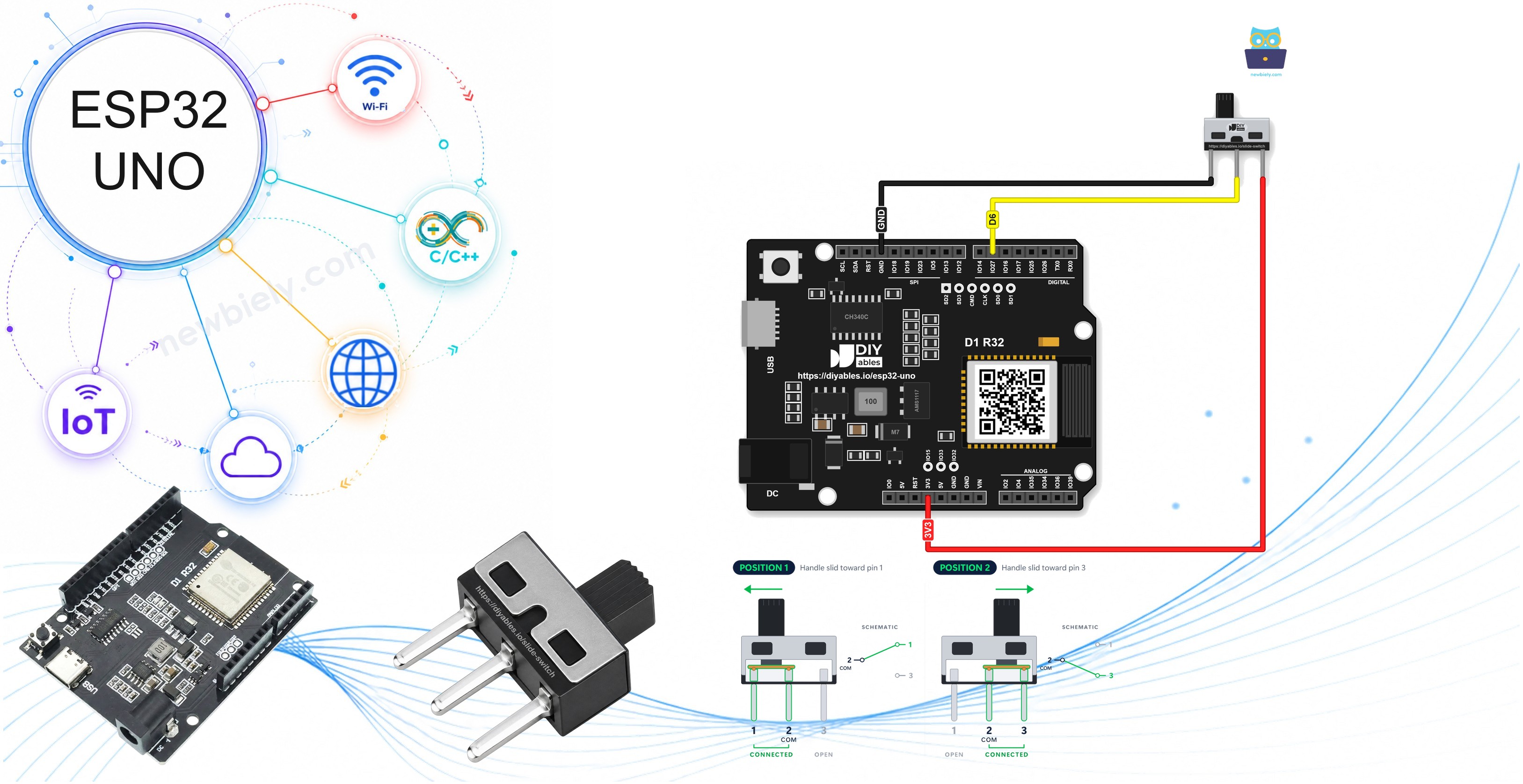
Components You Need
| 1 | × | ESP32 Uno-form Board | |
| 1 | × | USB Cable Type-A to Type-C (for USB-A PC) | |
| 1 | × | USB Cable Type-C to Type-C (for USB-C PC) | |
| 1 | × | Mini Slide Switch SS12D10 | |
| 1 | × | Jumper Wires |
Or you can buy the following kits:
| 1 | × | DIYables Sensor Kit (18 sensors/displays) |
Additionally, some of these links are for products from our own brand, DIYables .
The Slide Switch at a Glance
Two minutes here, and the wiring below will feel obvious.
The SS12D10 is a latching switch: slide the handle to one end and it stays there until you slide it back. A push button is different, because it springs back as soon as you let go. That makes the slide switch a good fit for anything that is a choice, not a moment.
Inside the plastic body, a small metal bridge always touches the middle leg. It also touches the outer leg on the side where the handle sits. So the handle decides which outer leg is joined to the middle one.
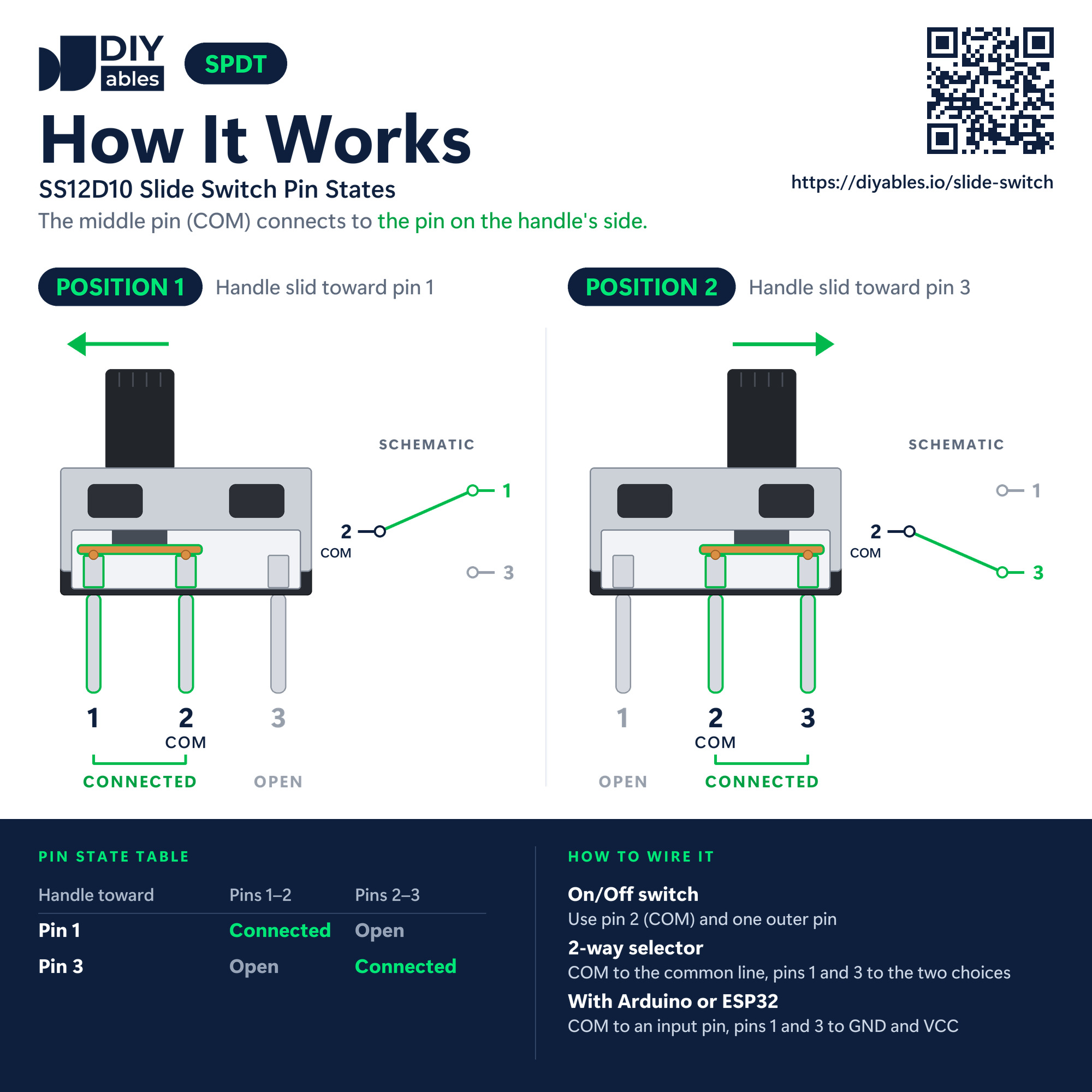
No labels are printed on the switch. The middle leg is always COM, and the two outer legs are pin 1 and pin 3:
| Pin | Where It Sits | ESP32 Uno Connection |
|---|---|---|
| Pin 1 | Outer leg | GND |
| Pin 2 (COM) | Middle leg, the common pin | D6 (GPIO27) |
| Pin 3 | Outer leg | 3.3V (no wire in the 2-wire version) |
This is what each handle position does to the D6 reading:
| Handle Position | Legs Joined | D6 Level with 3 Wires | D6 Level with 2 Wires (INPUT_PULLUP) |
|---|---|---|---|
| Toward pin 1 | Pin 1 and COM | LOW, printed as OFF | LOW, printed as ON |
| Toward pin 3 | COM and pin 3 | HIGH, printed as ON | HIGH, printed as OFF |
The main numbers from the DIYables product page:
| Feature | Value |
|---|---|
| Contact type | SPDT (1P2T), 2 positions |
| Legs | 3 in a row, 4.7 mm apart, 6.9 mm long |
| Handle length | 5 mm |
| Body size | about 12.8 x 6.7 x 18.2 mm |
| Mounting | Vertical through-hole |
| Contacts | Silver-plated brass |
| Contact rating | AC 125V 2A |
| Lifetime | More than 100,000 switching cycles |
| Operating temperature | -25°C to 80°C |
The 125V 2A rating tells you what the contacts can carry. In this project the switch only passes a tiny signal current into GPIO27, so the rating is far away.
ESP32 Uno Pinout
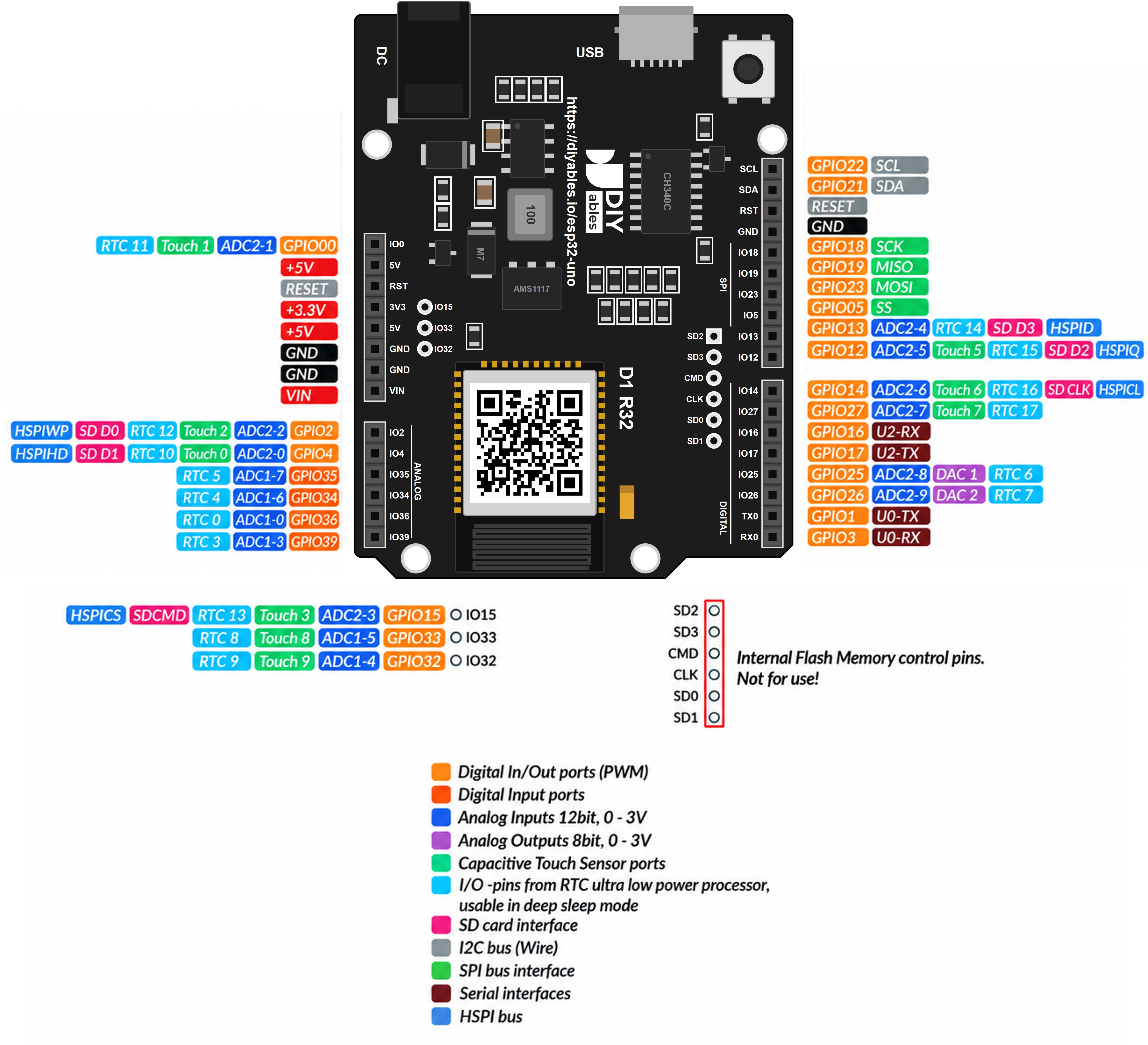
The wire goes to the hole printed D6, but the sketch says 27. The diagram explains it: D6 on the Uno-style header is GPIO27 on the ESP32 chip, and Arduino code for this board always uses the GPIO number.
How to Connect
Three jumper wires run from the switch legs to the board headers. No resistor is needed: COM always touches either GND or 3.3V, so GPIO27 is never left floating. The legs are bare metal, so a female jumper end pushed onto each leg is fine for a test. Solder the wires for a build that lasts.
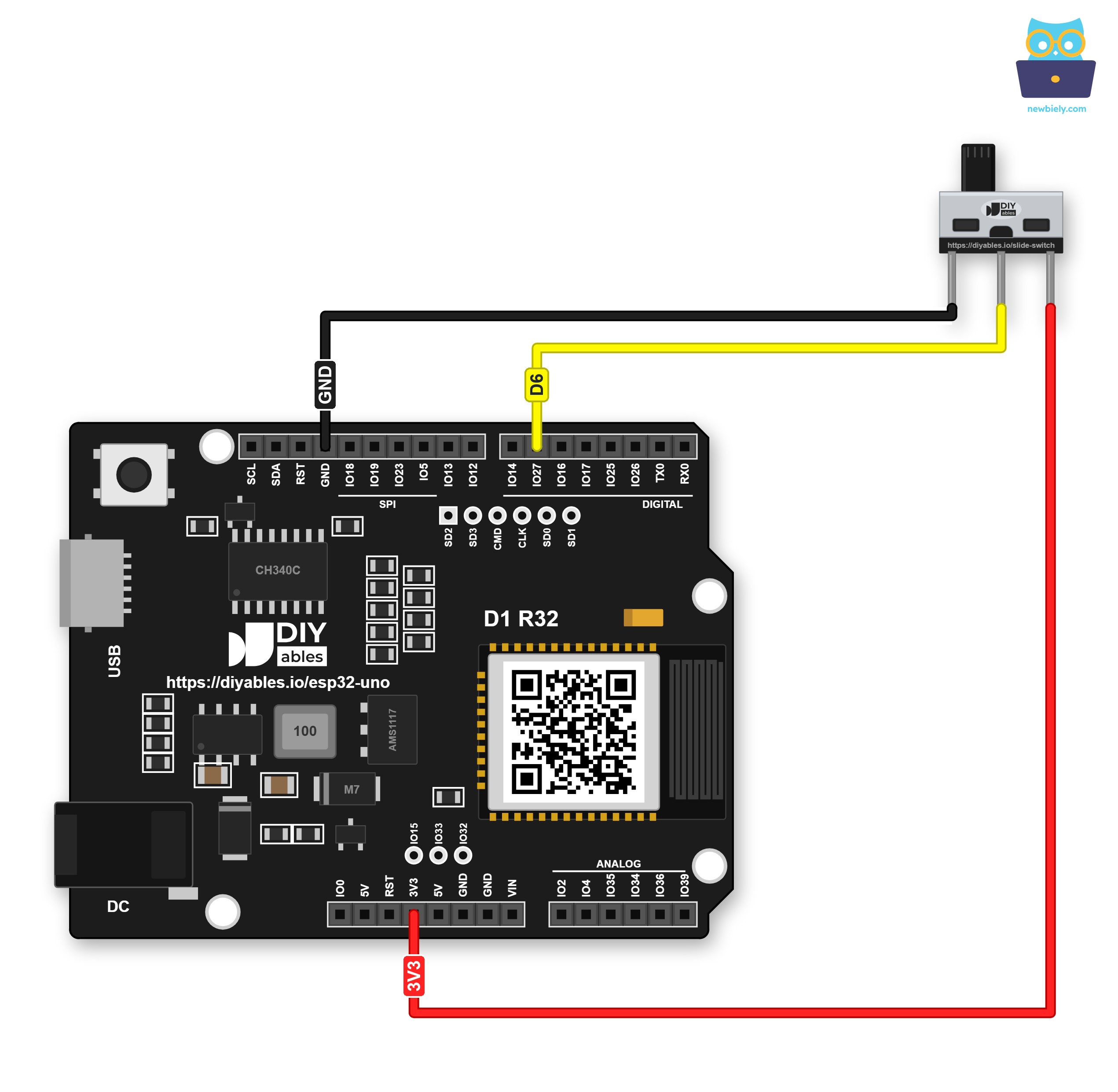
This image is created using Fritzing. Click to enlarge image
| Slide Switch Pin | ESP32 Uno Pin |
|---|---|
| Pin 1 | GND |
| Pin 2 (COM) | D6 (GPIO27) |
| Pin 3 | 3.3V |
A screw terminal keeps each wire tight, even when the board shakes. You can stack a Proto Screw Terminal Block Shield or a Screw Shield V2 on the ESP32 Uno and connect the wires to its screw terminals. Here is the same circuit wired through the Screw Shield V2:
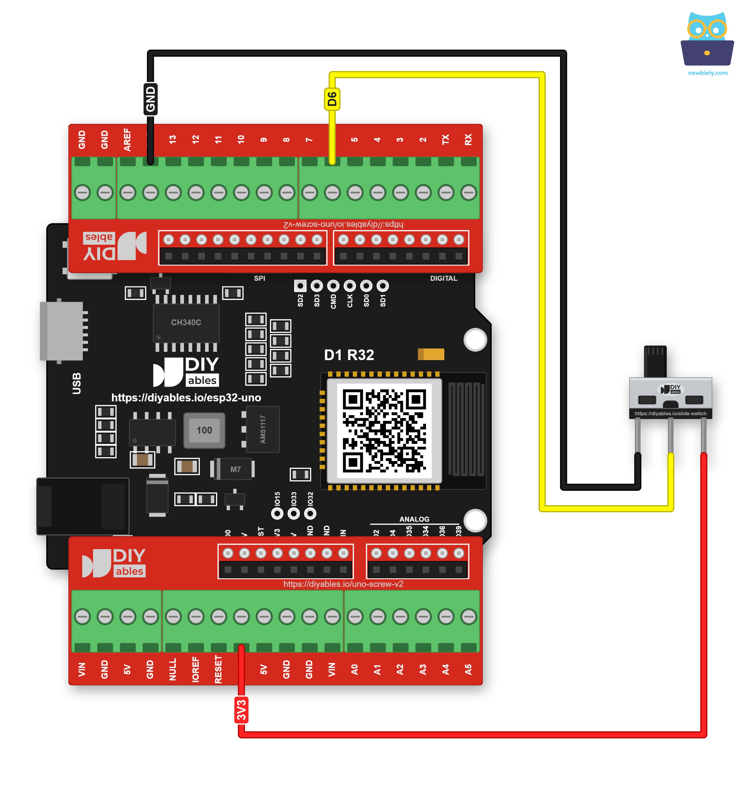
This image is created using Fritzing. Click to enlarge image
WARNING
Pin 3 belongs on the 3.3V header, never on 5V or VIN. With the handle toward pin 3, COM hands that voltage straight to GPIO27, and the ESP32 pins take 3.3V at most.
※ NOTE THAT:
Keep GPIO27 an input in every sketch. Never set it to OUTPUT while the switch is connected: the switch ties the pin straight to 3.3V or to GND, so an output level that disagrees would short the pin.
Good to know: this page uses D6 (GPIO27), not D7. D7 is GPIO14, which puts out a signal while the ESP32 boots, and the switch ties its pin straight to GND or 3.3V, so a quiet pin is the better choice. GPIO27 has no boot role, and it has the internal pull-up that the 2-wire version needs.
ESP32 Uno Code - Read the Slide Switch with 3 Wires
At power-up the sketch reads the handle once and prints where it is. After that it stays silent until the level on GPIO27 changes. Then it waits 50 ms, because metal contacts rattle for a moment when the handle moves, and reads again. Only a change that is still there gets printed.
Upload and Test
- First sketch on the ESP32 Uno? Install the ESP32 core with ESP32 Uno - Getting Started.
- Wire the switch from the table: pin 1 to GND, COM to D6, pin 3 to 3.3V.
- Plug the board in with the USB Type-C cable.
- Pick the board: in Arduino IDE choose ESP32 Dev Module and the CH340 COM port.
- Paste the sketch into a new Arduino IDE window.
- Click Upload and wait until the IDE says it is done.
- Open the Serial Monitor at 9600 baud, then press the reset (EN) button once to see the start line.
- Slide the handle from end to end a few times. With the handle starting toward pin 3, the log looks like this:
- Pro tip: if ON shows up when the handle points at pin 1, the GND and 3.3V wires are swapped. That is harmless. Swap the two outer wires, or just swap the two messages in the code.
ESP32 Uno Code - 2-Wire Slide Switch with INPUT_PULLUP
Fewer wires, and no 3.3V wire at all: that is the reason to use this version. Just remove the pin 3 wire. The ESP32 has a pull-up resistor inside GPIO27, and INPUT_PULLUP switches it on, so the pin sits at 3.3V whenever COM is not joined to GND.
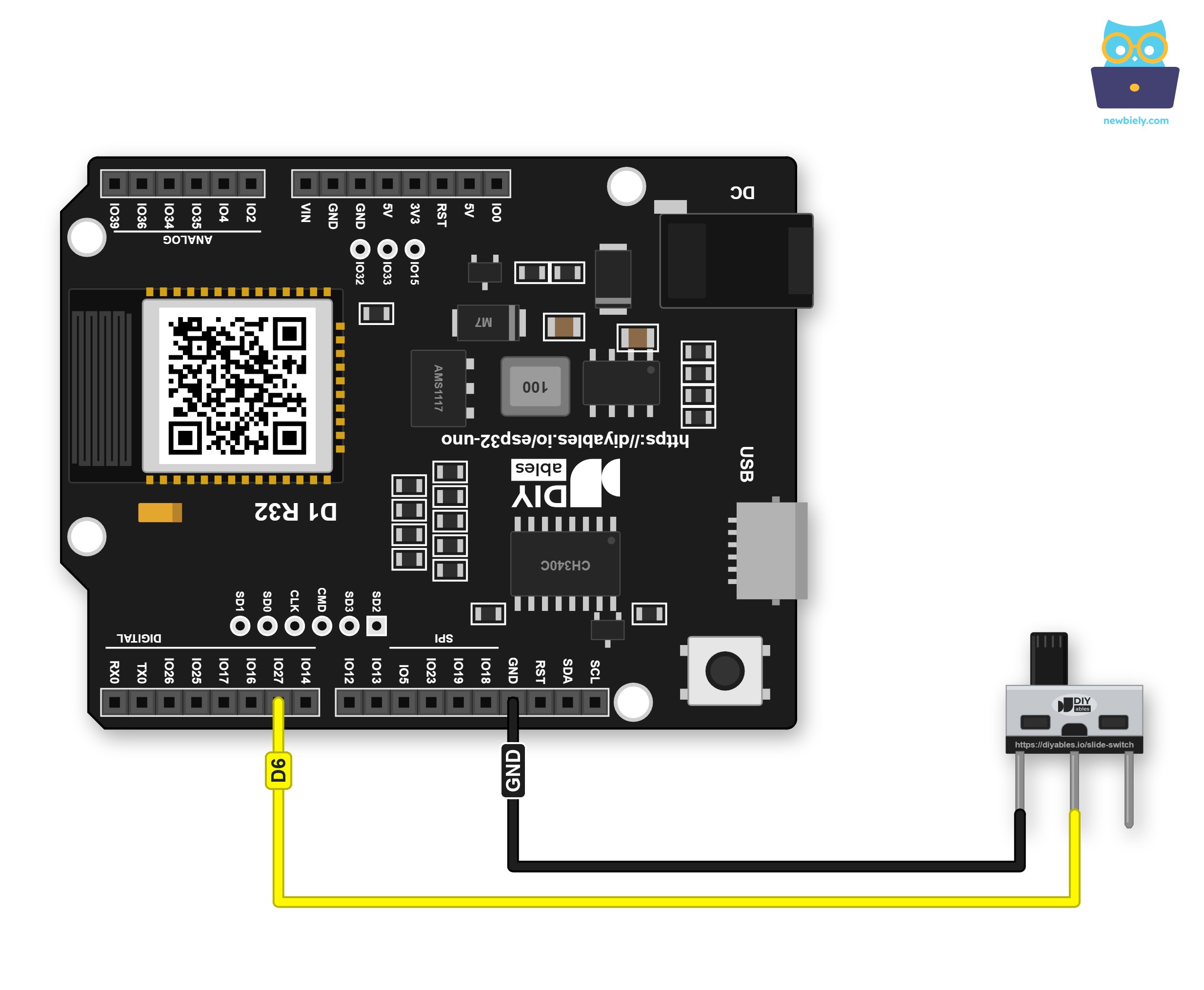
This image is created using Fritzing. Click to enlarge image
| Slide Switch Pin | ESP32 Uno Pin |
|---|---|
| Pin 1 | GND |
| Pin 2 (COM) | D6 (GPIO27) |
| Pin 3 | Not connected |
The logic turns around here. Handle toward pin 1: COM touches GND, the pin reads LOW, and the sketch prints ON. Handle toward pin 3: COM touches nothing, the pull-up wins, the pin reads HIGH, and the sketch prints OFF.
Upload and Test
- Pull the pin 3 wire off the 3.3V header. The GND and D6 wires stay.
- Upload this sketch in place of the first one.
- Open the Serial Monitor at 9600 baud and press the reset (EN) button.
- Move the handle to each end and back. This time the handle starts toward pin 1:
- Pro tip: leave pin 3 empty in this version. A wire from pin 3 to GND would make both positions read LOW, and the sketch could never see OFF.
Video Tutorial
Code Explanation
The two sketches are the same program with one line and one test changed. This table walks through the parts that matter.
| Code Part | What It Does |
|---|---|
| #define SLIDE_SWITCH_PIN 27 | Points the code at GPIO27, the D6 hole where COM is wired |
| pinMode(SLIDE_SWITCH_PIN, INPUT) | 3-wire sketch, the switch itself drives the pin HIGH or LOW |
| pinMode(SLIDE_SWITCH_PIN, INPUT_PULLUP) | 2-wire sketch, turns on the resistor inside GPIO27 that pulls it to 3.3V |
| digitalRead() in setup() | Reads the handle once at power-up, so the first position is printed too |
| last_state | Holds the last confirmed level, so a move can be spotted |
| delay(SETTLE_TIME) | Waits 50 ms while the contacts bounce, then the pin is read again |
| printPosition() | HIGH means ON in the 3-wire sketch, LOW means ON in the 2-wire sketch |
The 50 ms wait only happens while the handle moves. The rest of the time loop() runs at full speed, so this pattern is fine next to other code.
Go Wireless: Show the Switch Position on Your Phone
The ESP32 Uno has WiFi and Bluetooth built in. A slide switch on a box in the garage can tell your phone whether the box is set to "away" or "home". Send the text from printPosition() to a web page or the Bluetooth app instead of, or next to, the Serial Monitor.
Try These Next
- Use the switch as a WiFi on/off setting: read it once in setup() and only start WiFi when it is ON.
- Add a second slide switch on D5 (GPIO16). Two switches give four modes: 00, 01, 10 and 11.
- Let the switch pick a blink speed for an LED: fast when ON, slow when OFF.
- Mount the switch on the side of a small box, so the setting can be changed without opening it.
Troubleshooting
| Problem | Possible Cause | Solution |
|---|---|---|
| No COM port in Arduino IDE | CH340 driver missing or a charge-only cable | Install the CH340 driver and use a USB cable that carries data |
| Upload stops at "Waiting for download" | Board did not enter download mode | Hold the BOOT button as the upload starts, then let go |
| Always OFF with 3 wires | Pin 3 wire loose or not on 3.3V | Push the pin 3 wire firmly onto the 3.3V header |
| Never changes in either position | An outer leg is on D6 instead of the middle leg | Put the middle leg (COM) on D6 and the outer legs on GND and 3.3V |
| Never changes with correct wiring | Code uses 6 instead of 27 | Use 27, since D6 is GPIO27 |
| Random ON and OFF with 2 wires | Sketch still uses INPUT | Upload the INPUT_PULLUP sketch when pin 3 has no wire |
| ON and OFF are swapped | GND and 3.3V wires swapped, or you run the 2-wire sketch | Swap the outer wires, or swap the two messages in the code |
| Two lines for one slide | Contacts bounce longer than 50 ms | Raise SETTLE_TIME to 80 |
| No start line in the log | Serial Monitor opened after the board started | Press the reset (EN) button once |
| Odd symbols before the first line | ESP32 boot messages are sent at 115200 baud | Ignore them, the sketch output at 9600 baud follows |
FAQ
Which leg of the slide switch is COM?
The middle one. The switch has no printed labels, but on the SS12D10 the middle leg is always COM. The two outer legs are pin 1 and pin 3.
Do I need a resistor with the slide switch?
Not with three wires. COM is always joined to GND or 3.3V, so the pin always has a clear level. With two wires you still need no part, because INPUT_PULLUP uses the resistor inside the ESP32.
Can pin 3 go to 5V on the ESP32 Uno?
No. COM passes the pin 3 voltage straight to GPIO27, and ESP32 pins are not 5V tolerant. Use the 3.3V header.
Why D6 and not D7?
D7 is GPIO14, which puts out a signal while the ESP32 boots. The switch ties its pin hard to GND or 3.3V, so a pin that stays quiet at boot is better. GPIO27 (D6) has no boot role.
Why does the code use 27 and not 6?
The ESP32 core uses GPIO numbers. The hole printed D6 is GPIO27, so the sketch has #define SLIDE_SWITCH_PIN 27.
Should I use the 3-wire or the 2-wire version?
Both work. The 3-wire version reads HIGH as ON, which is easy to follow. The 2-wire version saves one wire and does not need the 3.3V pin, but ON reads as LOW.
Why does ON read LOW with INPUT_PULLUP?
In the 2-wire version, the only way to change the pin is to join it to GND. The pull-up keeps it HIGH the rest of the time. So the position that connects COM to GND, toward pin 1, is the one that reads LOW.
Can I set the switch pin to OUTPUT?
No. The switch connects the pin directly to 3.3V or GND. An output that drives the other level would cause a short. Keep it as INPUT or INPUT_PULLUP.
Does the 125V 2A rating matter here?
No. That is the most the contacts can carry. Here they only pass a tiny signal current into one GPIO pin.
Can I use other pins for COM?
Yes. D2 to D5, D9 and D11 to D13 work for both versions. A2 to A5 (GPIO35, 34, 36 and 39) work only with three wires, because these input-only pins have no internal pull-up. Skip D0 and D1, which carry the USB serial, and D8 (GPIO12), D10 (GPIO5) and A0 (GPIO2), which are boot strapping pins.
Can the slide switch wake the ESP32 Uno from deep sleep?
Yes. GPIO27 is an RTC pin. With the 3-wire version, esp_sleep_enable_ext0_wakeup(GPIO_NUM_27, 1) wakes the board when the handle is slid toward pin 3.