
ESP32 UNO - BTS7960 Motor Driver
Think of a rope winch at the top of a boat ramp. It pulls a small boat out of the water, stops, and later lets the rope run back out. Put a cart of firewood on the ramp instead, and the job is the same: one strong motor that turns both ways, starts gently and stops when you tell it to. A small motor driver is not made for a motor like that. The DIYables BTS7960 module is: it runs one big 12V DC motor in both directions, sets its speed with PWM, and its chips handle up to 43A. The ESP32 Uno form board controls it with four signal wires and a short sketch, with no library.
Steps on this page:
- Get to know the BTS7960 board, its eight control pins and its four big screw terminals
- Learn which pin levels give forward, reverse, brake and coast
- Connect the ESP32 Uno, the 12V adapter and the motor
- Run one sketch that winds in, brakes, pays out and coasts, again and again
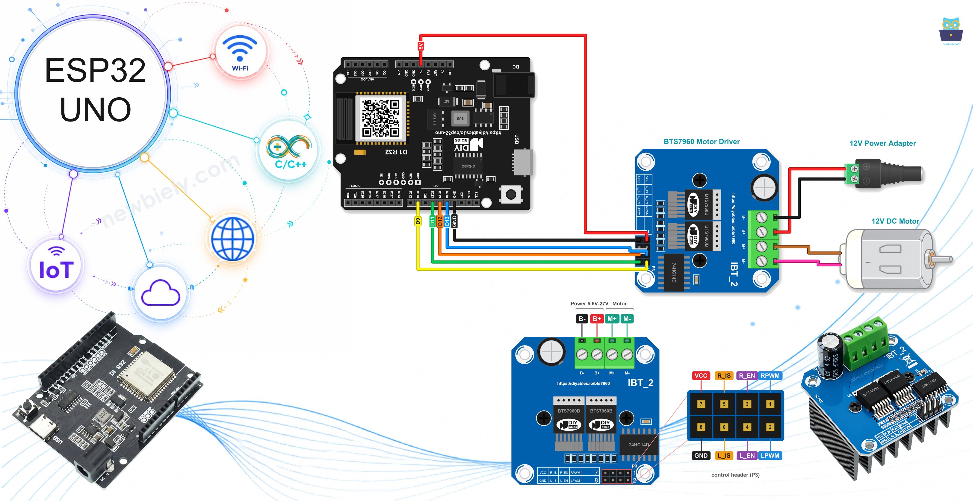
Components You Need
Or you can buy the following kits:
| 1 | × | DIYables Sensor Kit (18 sensors/displays) |
Additionally, some of these links are for products from our own brand, DIYables .
Good to know: size the 12V adapter for the motor, because the motor is the only thing it feeds. Its current rating must be higher than what the motor needs. The ESP32 Uno itself stays on USB power.
Meet the BTS7960 Motor Driver
Five minutes here will save you from the two classic mistakes: 12V on a board pin, and PWM on both inputs at the same time.
Two Infineon BTS7960B power chips do the heavy work. One chip alone can pull a motor lead up to the supply or down to ground, and that is called a half-bridge. Put two of them side by side and you get a full H-bridge, which is exactly what one brushed DC motor needs to turn both ways. PWM on the inputs sets the speed. Where an L298N or a DRV8833 runs out of breath, this board keeps going. People use it for wiper motors from old cars, big gear motors, winches, e-scooters, wheelchair motors and heavy robot bases. In shops you may also see it as IBT-2 or HW-039.
| Item | Spec |
|---|---|
| Power stage | two BTS7960B half-bridges from Infineon, forming one H-bridge |
| Motor count | one brushed DC motor, forward and reverse |
| Supply range on B+ and B- | 5.5V to 27V DC, so 6V, 12V and 24V motors all fit |
| Peak current | 43A, the point where the chips start limiting |
| Highest PWM on RPWM and LPWM | 25 kHz |
| Input buffer | 74HC14 chip, fed from the VCC pin |
| Built-in protection | limits the current, protects itself from overheating |
| Sold as | IBT-2 or HW-039 |
Read the 43A number as a ceiling, not a goal. The chips start to hold the current back at that level. In a long run, the motor should pull far less, and how much less depends on how well the heat sink gets rid of the heat.
Control Pins and Screw Terminals
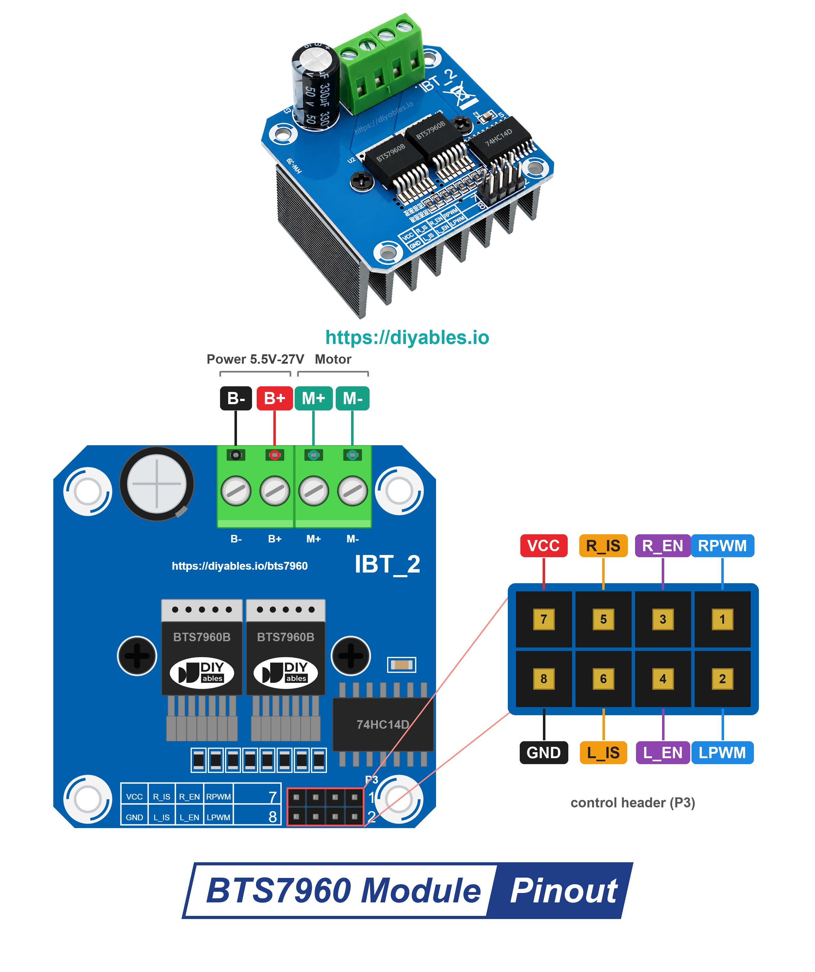
The control side is a block of eight male pins in two rows. The top row is VCC, R_IS, R_EN and RPWM. Right under them sit GND, L_IS, L_EN and LPWM, so each right-side pin sits on top of its left-side twin. On the board itself, the two sense pins carry the short labels R_S and L_S.
- RPWM: speed input for one direction, called forward on this page. It belongs to the right half-bridge.
- LPWM: speed input for the opposite direction, reverse. It belongs to the left half-bridge.
- R_EN: a HIGH level here wakes up the right half-bridge.
- L_EN: a HIGH level here wakes up the left half-bridge.
- R_IS and L_IS: current-sense and fault outputs. This project gives them no wire.
- VCC: feeds the small 74HC14 logic chip and the power LED, and nothing else. The motor never draws from this pin.
- GND: logic ground, already tied to B- on the module.
The four big screw terminals carry the heavy current:
- B+ and B-: this is where the motor supply comes in (5.5V to 27V). The 12V adapter lands here.
- M+ and M-: the motor's two leads are screwed in here.
Forward, Reverse, Brake and Coast
Picture the motor in the middle of four switches, two on each side. Each BTS7960B chip owns the two switches on its side, so it can tie its motor lead to B+ or to B-. Send PWM to RPWM and the right side keeps flicking to B+, while the left side rests on B-. Current runs through the motor, and the shaft turns forward. Send PWM to LPWM instead and the two sides swap jobs, so the current and the shaft go the other way. The duty cycle, 0 to 255 in the code, is the share of time the current is on, and that is the speed.
| Both Enables | RPWM | LPWM | Motor Result |
|---|---|---|---|
| HIGH | PWM, 0 to 255 | 0 | Forward, faster with a bigger duty cycle |
| HIGH | 0 | PWM, 0 to 255 | Reverse, faster with a bigger duty cycle |
| HIGH | 0 | 0 | Brake, the driver shorts the motor leads together, quick stop |
| LOW | 0 | 0 | Coast, driver switched off, the shaft spins down on its own |
WARNING
Keep RPWM or LPWM at 0 at every moment. PWM on both inputs at once is never allowed. That is why each helper in the sketch zeroes the other input before it writes a speed.
On a winch, brake and coast feel very different. Brake stops the drum quickly. Coast lets the drum turn freely, so a boat on the ramp could pull some rope back out. Still, the driver is not a parking brake: a real winch that must hold a load also needs a mechanical lock, such as a ratchet.
Power and Ground
Two supplies meet at this module, and each one has its own job.
| Supply | Module Pins | What It Powers |
|---|---|---|
| ESP32 Uno 5V pin | VCC and GND | logic chip (74HC14) and power LED |
| 12V adapter | B+ and B- | the motor, through the two power chips |
Feed VCC from the 5V pin of this board. VCC only runs the small buffer chip, and the maker of the module says it needs 5V. Signals from 3.3V up to 5V are fine on the control inputs, so the ESP32 Uno GPIO pins can be connected as they are. Signals only travel one way here, from the board to the module. The four inputs have pull-down resistors, and the two sense outputs, R_IS and L_IS, have no wire, so no 5V and nothing from the motor side can find its way back into a GPIO.
Ground needs only one wire. GND and B- are already joined on the module, so one wire between a GND pin of the ESP32 Uno and the GND pin of the module is enough. After that, the board and the 12V adapter share the same 0V.
ESP32 Uno Pinout
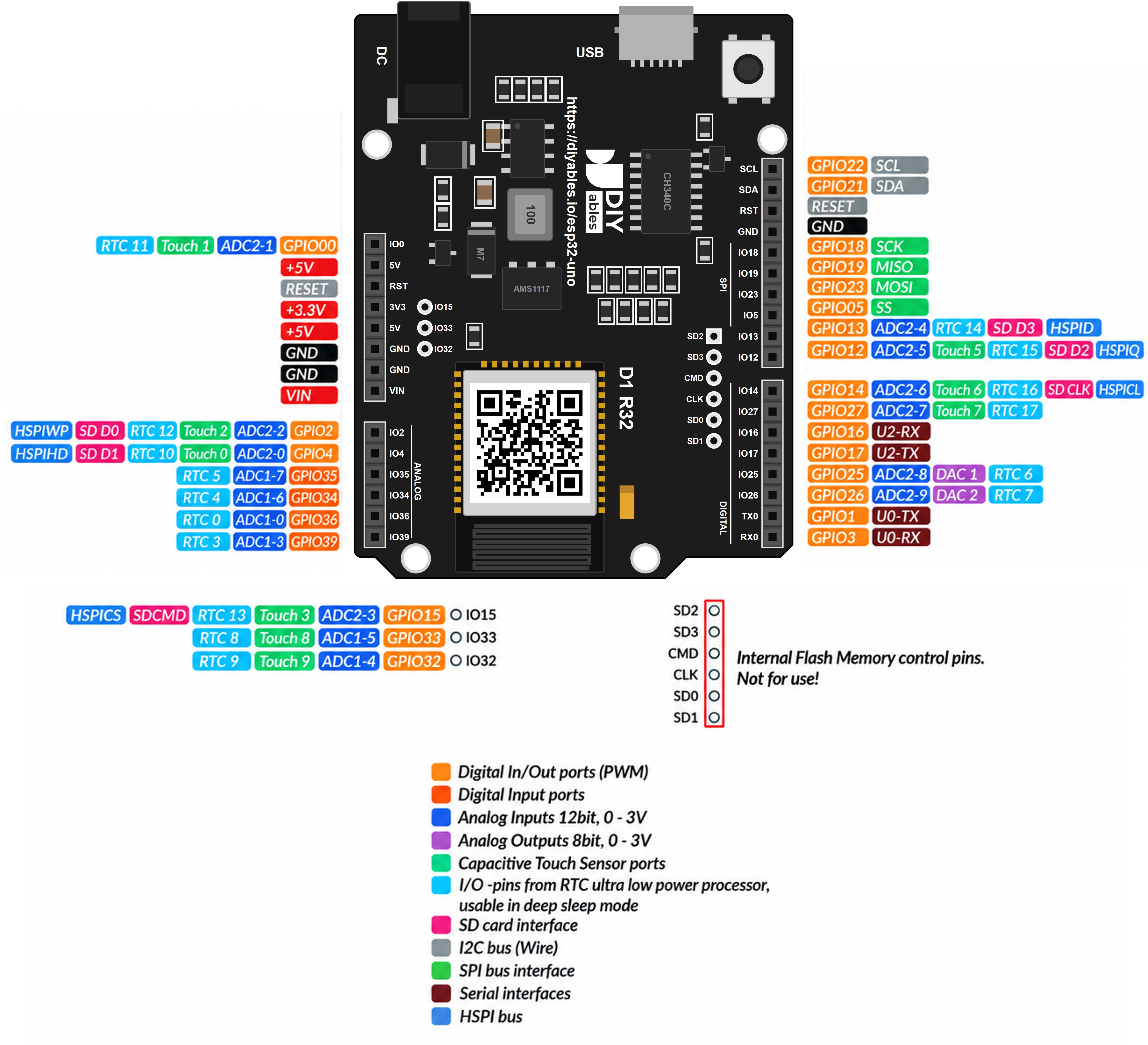
On the board you see D9, D11, D12 and D13. In the sketch you see 13, 23, 19 and 18. Both are right. The ESP32 Uno keeps the Uno names on its headers, but Arduino code for this board uses the GPIO numbers of the ESP32 chip. The map below links the two.
How to Connect
The wiring has two parts. The signal part runs from the ESP32 Uno to the control pins: four signal wires, plus 5V and GND. The power part never touches the board: the 12V adapter reaches B+ and B- through the DC power jack, and the motor sits on M+ and M-.
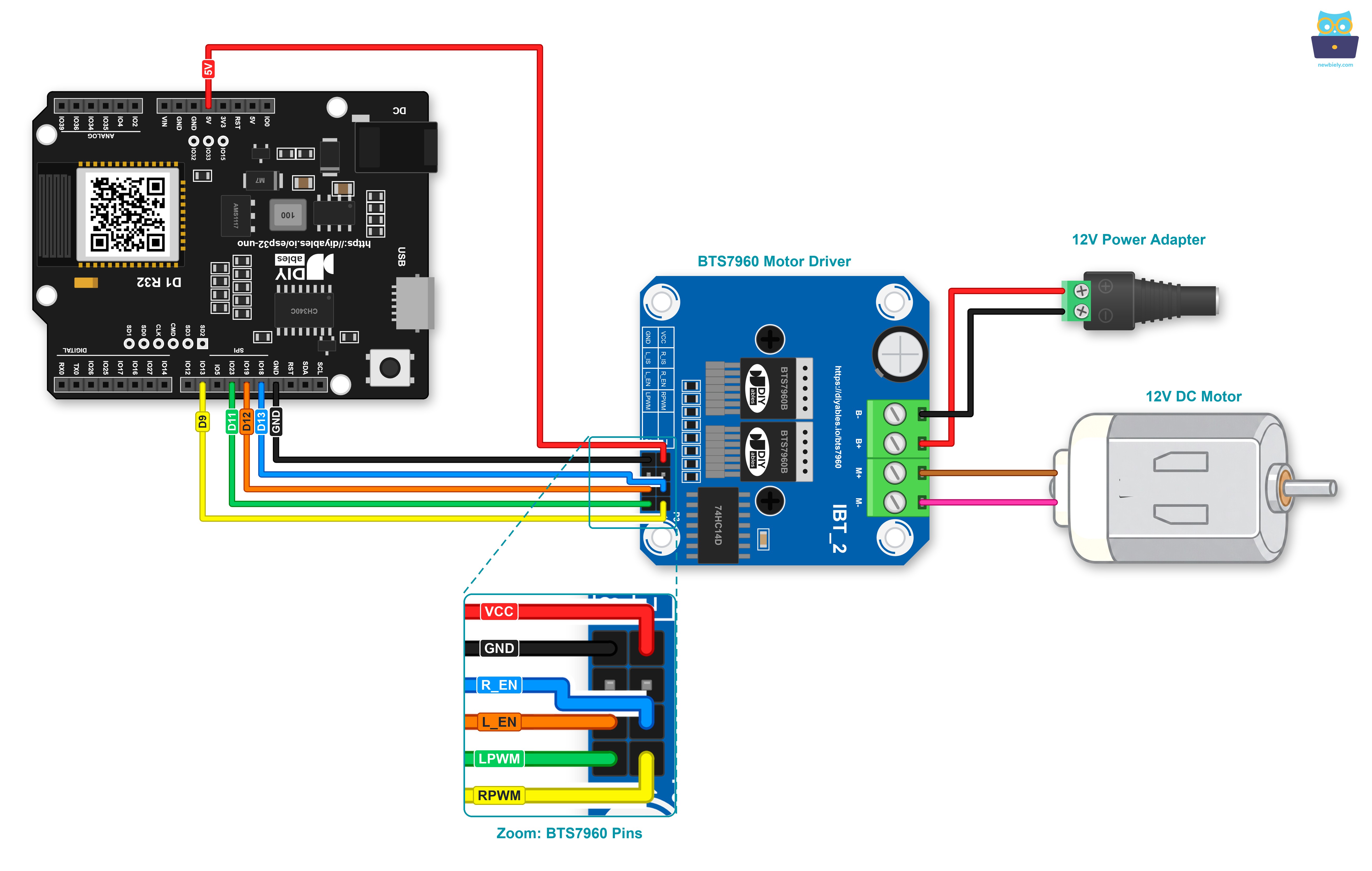
This image is created using Fritzing. Click to enlarge image
| Module Pin | Wire It To |
|---|---|
| RPWM | D9 (GPIO13) |
| LPWM | D11 (GPIO23) |
| R_EN | D13 (GPIO18) |
| L_EN | D12 (GPIO19) |
| VCC | 5V |
| GND | GND |
| R_IS, L_IS | no wire |
| B+ | DC power jack + (12V adapter) |
| B- | DC power jack - (12V adapter) |
| M+, M- | 12V DC motor leads, either way round |
Jumper wires are good for a quick test, but not for a final build. Try a Screw Shield V2 or a Proto Screw Terminal Block Shield: it sits on the ESP32 Uno, and each pin gets its own screw terminal. The pins do not change. Just connect each wire to the matching screw terminal:
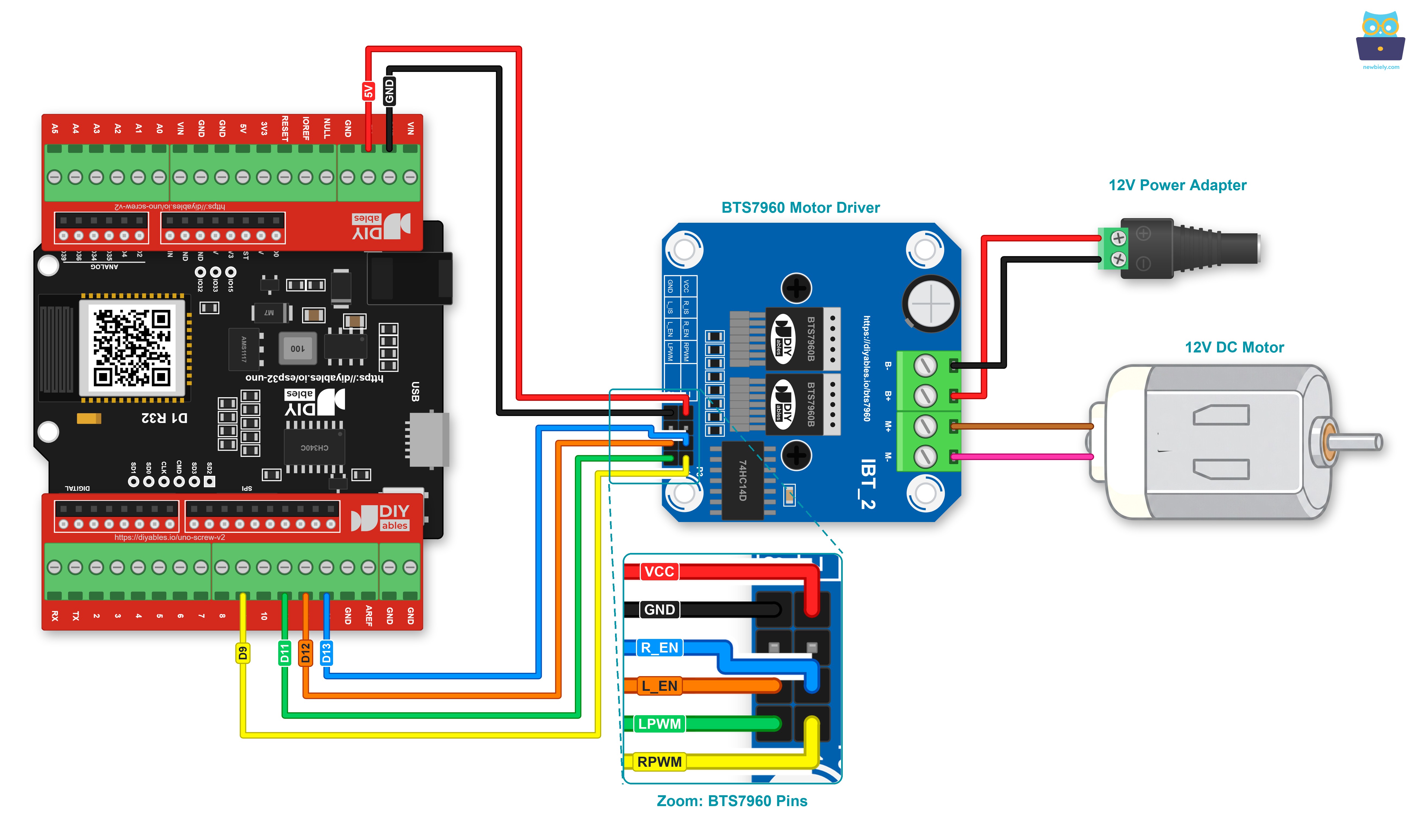
This image is created using Fritzing. Click to enlarge image
WARNING
Keep the 12V side away from the ESP32 Uno. B+ connects only to the adapter, never to a board pin. ESP32 pins take 3.3V at most, and one touch of 12V can kill the board.
※ NOTE THAT:
Before the adapter goes into the wall socket, look at the + and - screws of the DC power jack once more. If B+ and B- get the supply the wrong way round, the module can be damaged. The adapter is the last thing you plug in.
Good to know: LPWM uses D11, not D10. D10 is GPIO5, a boot strapping pin that puts out a signal while the ESP32 starts. A motor input should stay quiet during boot, so D10 is skipped on purpose. D9, D11, D12 and D13 have no boot role.
ESP32 Uno Code - Wind In, Brake, Pay Out and Coast
The sketch plays one winch cycle again and again. First it winds in: RPWM climbs from 0 to 255 in about 3 seconds, holds full speed for 2 seconds, and drops back to 0. A 1-second brake follows. Then the motor pays out in reverse at half speed for 2 seconds, and finally the driver switches off for a 2-second coast. You get one line in the Serial Monitor per step. Four small helpers, motorForward(), motorReverse(), motorBrake() and motorCoast(), keep the "one PWM input at 0" rule in one place.
Upload and Test
- Never used the ESP32 Uno before? ESP32 Uno - Getting Started installs the ESP32 core in Arduino IDE first.
- Leave the 12V adapter out of the socket for now. It goes in after the upload.
- Wire everything as the table says: four signal wires, 5V, GND, then the power jack and the motor at the big screw terminals.
- Plug the USB Type-C cable into the ESP32 Uno and into the PC.
- Set up Arduino IDE: choose ESP32 Dev Module as the board, then the COM port of the CH340 chip.
- Paste the sketch, then press Upload.
- Plug in the 12V adapter once the upload is done.
- Open the Serial Monitor (9600 baud) and keep an eye on the shaft. Missed the first line? Press the reset (EN) button once. One cycle looks like this:
- Pro tip: if the motor pays out while the log says "Wind in", swap M+ and M- at the screw terminal. The code stays as it is.
At the slow end of each ramp, the motor may sing a little. That sound is the PWM: analogWrite() on the ESP32 switches at about 1 kHz, a pitch your ear can pick up. Many motors also need a certain duty cycle before they start to turn, so the first part of the ramp can be quiet and still.
Video Tutorial
Code Explanation
| Code Part | What It Does |
|---|---|
| #define RPWM_PIN 13 | The D9 hole is GPIO13, so the code uses 13. LPWM, R_EN and L_EN follow the same rule with 23, 18 and 19 |
| analogWrite() to 0 before driverOn() | Both inputs are at 0 before the driver wakes up, so the motor cannot jump at power-up |
| motorForward(speed) | Sets LPWM to 0 first, then sends the speed to RPWM |
| motorReverse(speed) | Sets RPWM to 0 first, then sends the speed to LPWM |
| motorBrake() | Both inputs at 0 with the enables still HIGH, so the motor stops fast |
| motorCoast() | Both inputs at 0 and the enables LOW, so the shaft spins down freely |
| STEP_TIME 12 | 256 steps x 12 ms, so each ramp takes about 3 seconds |
| driverOn() at the end of loop() | Wakes the driver again after the coast, before the next wind-in |
One full cycle lasts about 13 seconds: two ramps of 3 seconds, 2 seconds at full speed, 1 second of brake, 2 seconds of reverse and 2 seconds of coast.
ESP32 Uno vs UNO R4 for This Project
Moving this project over from an UNO R4? The 12V half stays as it is. Only the signal wires and the pin numbers change.
| Item | Arduino UNO R4 | ESP32 Uno |
|---|---|---|
| Logic voltage | 5V | 3.3V |
| BTS7960 VCC wire | 5V | 5V |
| RPWM | D9 | D9 (GPIO13) |
| LPWM | D10 | D11 (GPIO23) |
| R_EN | D12 | D13 (GPIO18) |
| L_EN | D11 | D12 (GPIO19) |
| Pin numbers in the code | 9, 10, 12, 11 | 13, 23, 18, 19 |
| Board to pick in Arduino IDE | UNO R4 WiFi or UNO R4 Minima | ESP32 Dev Module |
The truth table, the helper functions and the 12V wiring do not change. On both boards, the VCC wire goes to the 5V pin, even though the ESP32 Uno sends 3.3V signals.
BTS7960 or L298N?
Both can run a 12V DC motor in both directions. The size of the motor decides which one fits.
| Item | L298N | BTS7960 |
|---|---|---|
| Motors per board | 2 | 1 |
| Current | about 2A per motor | much higher, current limit 43A |
| Voltage lost inside the driver | about 2V | very little |
| Control pins per motor on this board | 3 (ENA, IN1, IN2) | 4 (RPWM, LPWM, R_EN, L_EN) |
| Good for | small robot cars, two small motors | winches, wiper motors, heavy robots |
For a small motor, the DRV8833 is the easier start: see ESP32 Uno - DC Motor. Does your fan or pump only need to turn one way? Then a MOSFET module does the job with a single pin.
Go Wireless: Run the Winch from Your Phone
The ESP32 Uno has WiFi and Bluetooth on board, so the winch does not need a cable to a button box. A joystick app fits well: push up to wind in, pull down to pay out, and the distance from the middle sets the speed. Pass that number to motorForward() or motorReverse(), and call motorBrake() when the stick is back in the middle.
If the phone loses the link, the motor keeps its last command. Add a timeout that calls motorBrake() when no command arrives for one second.
Try These Next
- Stop at the top: put a limit switch at the end of the ramp, and call motorBrake() when the boat or the cart presses it.
- Two buttons: hold one button to wind in and another one to pay out. Release both to brake.
- Speed knob: read a potentiometer, map it to 0 to 255 and pass the value to motorForward().
- Count the drum turns: a slotted disc on the drum and the IR slotted optical speed sensor tell you how much rope is wound in.
Function References
Troubleshooting
| Problem | Possible Cause | Solution |
|---|---|---|
| Lines appear in the log, but the shaft stays still | Adapter unplugged, or its + and - reach the wrong screws | Plug in the adapter, then check that + is on B+ and - is on B- |
| Shaft stays still and the module LED is dark | The VCC or GND wire is missing or loose | Put the VCC wire on the 5V pin and check the GND wire |
| Forward works, reverse never comes | LPWM wire loose or in the wrong hole | Put LPWM on D11 (GPIO23) |
| Reverse works, forward never comes | RPWM wire loose or in the wrong hole | Put RPWM on D9 (GPIO13) |
| Winds in when the log says "Pay out" | Motor leads reversed | Swap the wires on M+ and M- |
| Motor jerks or acts at random | GND wire loose, so there is no common ground | Push the GND wire firmly onto both pins |
| Hum or whine at low speed | About 1 kHz PWM from analogWrite(), this is normal | Ignore it, or see the FAQ about the PWM frequency |
| Shaft stays still at the start of each ramp | Duty cycle too low to start the motor | Normal. To skip it, start the ramp from a higher value, for example 60 |
| Module gets very hot | Motor current too close to the limit for a long run | Use a lighter load, and keep air moving around the heat sink |
| Arduino IDE lists no COM port | CH340 USB driver not installed, or the cable only charges | Add the CH340 driver and switch to a USB-C cable made for data |
| Strange symbols before the first line | The ESP32 prints boot messages at 115200 baud | Ignore them, the sketch itself prints at 9600 baud |
FAQ
Why does the BTS7960 VCC pin go to 5V when the ESP32 Uno works at 3.3V?
The module maker rates the VCC supply at 5V, and the only part on it is the 74HC14. The control inputs work with 3.3V signals, so the ESP32 Uno outputs are read as HIGH. Pull-down resistors sit on those inputs, so no 5V flows back into the board. The motor itself runs from B+ and B-.
Can the ESP32 Uno power the motor?
No. The motor gets its power only from the 12V adapter on B+ and B-. The ESP32 Uno sends the signals and feeds the small logic chip, nothing more.
Can the module really carry 43A?
Only as a short peak. At 43A, the chips begin to cut the current back. For steady running, plan for far less. How well the heat sink cools the chips sets the real long-run number.
What is the difference between brake and coast?
Brake keeps the enables HIGH and both PWM inputs at 0. The driver shorts the motor leads together, and the shaft stops quickly. Coast pulls the enables LOW. The driver lets go of the motor, and the shaft spins down on its own.
Can I use a 24V motor?
Yes. B+ and B- accept 5.5V to 27V, so a 24V motor with a 24V adapter works. The ESP32 Uno side and the sketch stay the same.
Why is LPWM on D11 and not D10?
D10 is GPIO5, a boot strapping pin that puts out a signal while the ESP32 boots. D11 (GPIO23) stays quiet at boot, so the motor input gets no stray pulses.
Why does the sketch use 13, 23, 18 and 19?
Arduino code for the ESP32 Uno uses GPIO numbers. The holes D9, D11, D13 and D12 are GPIO13, GPIO23, GPIO18 and GPIO19.
Do I need the R_IS and L_IS pins?
Not for this project. They report current and faults, and this sketch does not read them. Leave them unconnected.
Can I drive R_EN and L_EN from one pin?
Yes. The sketch always sets them together, so one pin, such as D13, can drive both. You keep forward, reverse, brake and coast, and you save one pin.
Can I make the motor quieter?
The hum comes from the 1 kHz PWM. Recent esp32 cores have analogWriteFrequency() to change it. RPWM and LPWM take PWM up to 25 kHz, so keep any new frequency at or under that.