
Arduino UNO R4 - PC817 Optocoupler: Monitor 12V/24V DC Input Signal
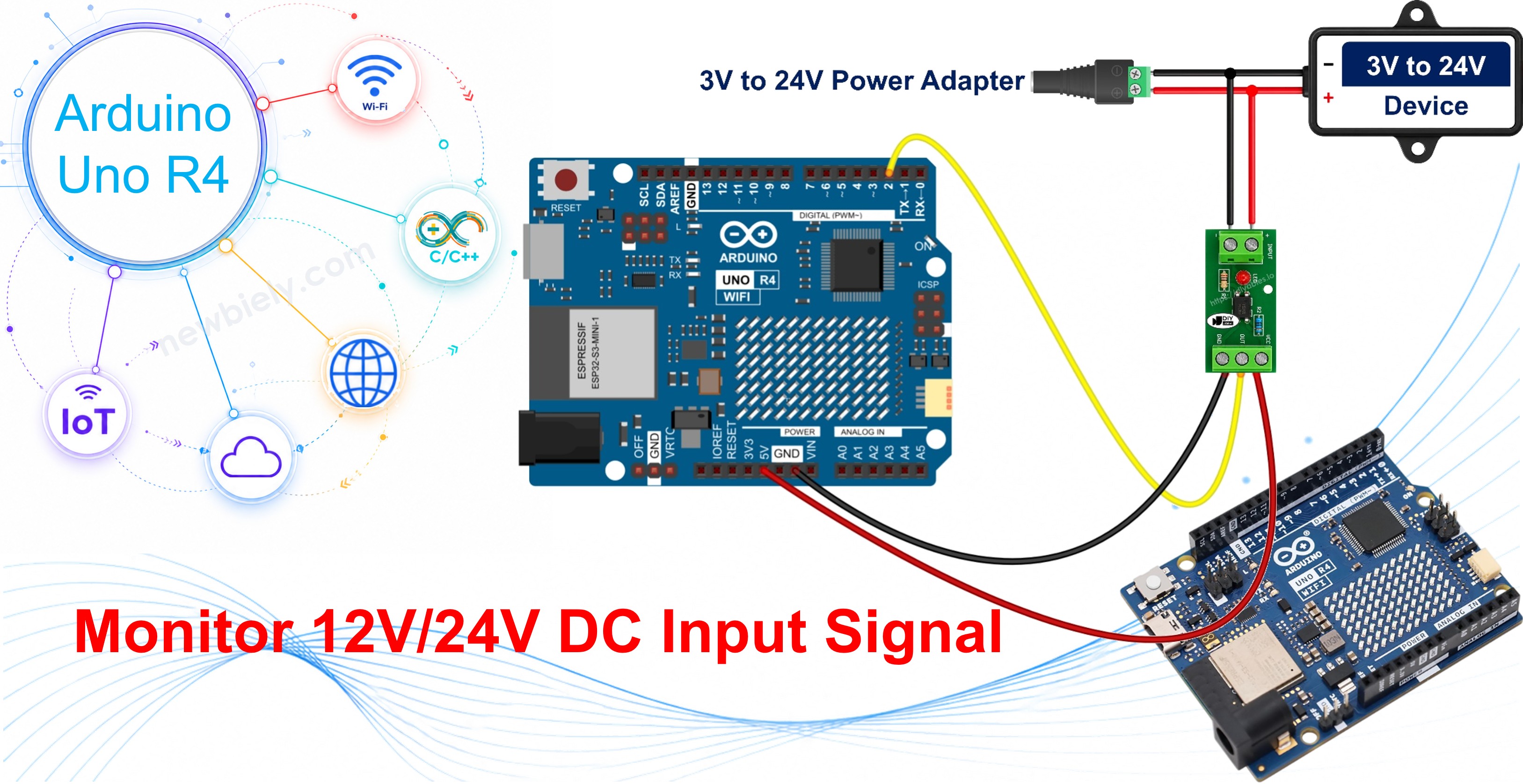
In this guide, we will learn how to use the PC817 optocoupler with the Arduino UNO R4 to answer a question about a 12V or 24V device — is it actually running right now? — without wiring that voltage to the board. In detail, we will learn:
- How a PC817 optocoupler module protects the Arduino UNO R4
- How to pick the right module variant for a 3.3V, 5V, 12V or 24V signal
- How to wire the module to the Arduino UNO R4, and how to find out whether its output is active LOW or active HIGH
- How to tap the module across a device, in parallel, so the reading follows the device itself
- How to program the Arduino UNO R4 to read the isolated digital input
- How to build the same input from the bare PC817 chip, if you would rather solder than buy
Hardware Preparation
Or you can buy the following kits:
| 1 | × | DIYables STEM V4 IoT Starter Kit (Arduino included) | |
| 1 | × | DIYables STEM V4B IoT Starter Kit (Arduino included) | |
| 1 | × | DIYables Sensor Kit (18 sensors/displays) |
Additionally, some of these links are for products from our own brand, DIYables .
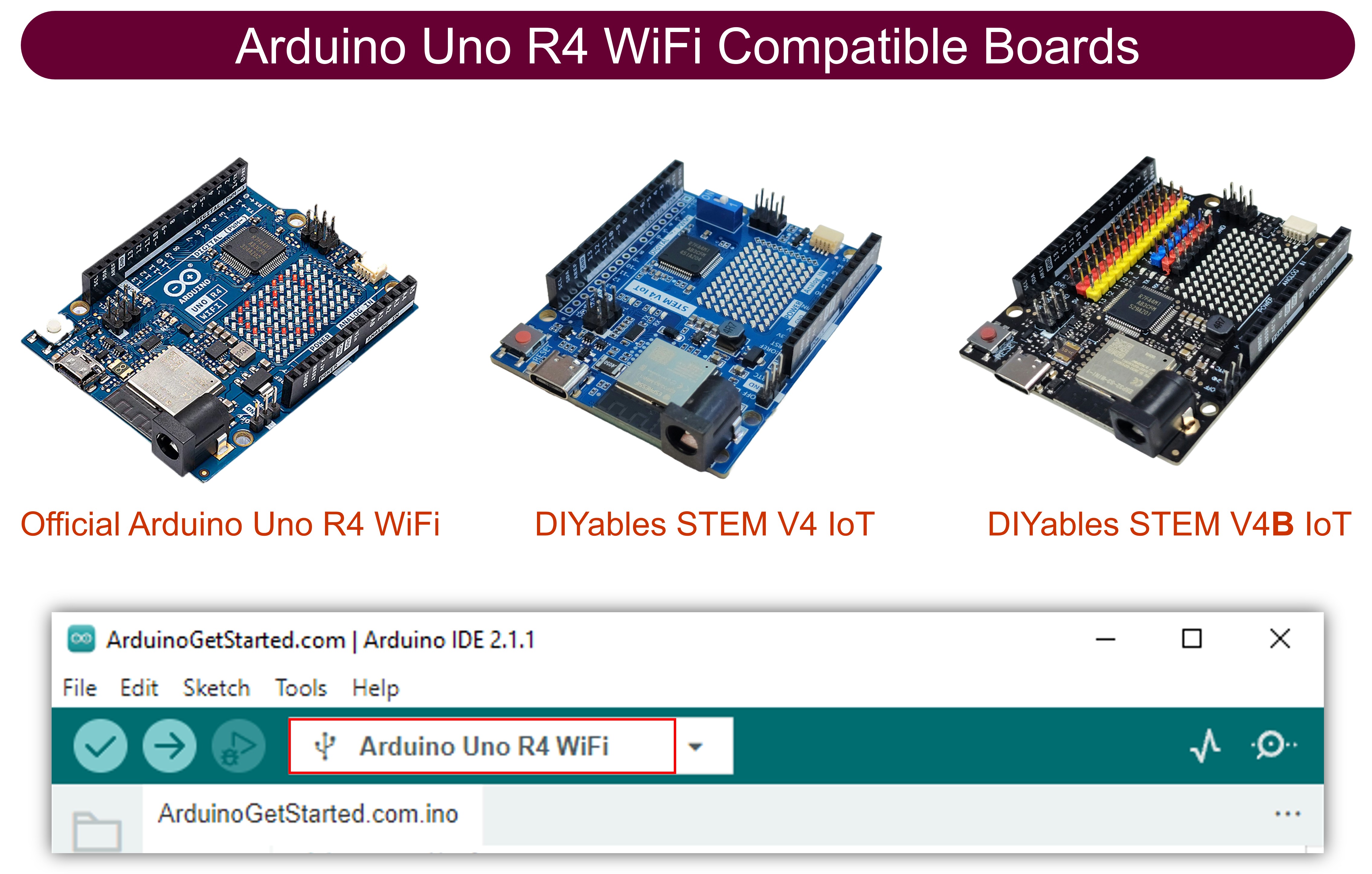
Buy one module variant - the one that matches the signal you intend to watch. The table further down says which.
Overview of PC817 Optocoupler
The PC817 is a 4-pin optocoupler, also sold under the names photocoupler and opto-isolator. Inside its plastic body there is an infrared LED facing a phototransistor across an insulating gap: when current flows through the LED, its light switches the transistor on, so the signal crosses as light instead of electricity — which is why the two sides stay electrically separate.
That gap is what makes the PC817 useful to an Arduino UNO R4 owner. A 12V or 24V line wired straight into a digital pin destroys the board. Through a PC817, the Arduino UNO R4 only ever sees its own 5V, while the high-voltage side stays on the far side of the gap. Typical hobby-to-tutorial jobs look like this:
- Watching the 12V output of a garage-door or gate controller so a sketch knows when the gate is being driven
- Checking whether a 12V automotive accessory line is live before a project draws current from it
- Monitoring the 24V enable line of a bench power supply
In each of those jobs the useful question is not really whether a wire is live, but whether the thing on the end of that wire is on or off at this moment, and that is what the PC817 hands to the sketch.
The Arduino UNO R4 is worth a special note here. Unlike most modern 3.3V boards, the UNO R4 runs its I/O at 5V, so the output side of the optocoupler is pulled up to 5V on this board, and a pin reads either 5V or 0V.
Specifications
| Parameter | Value |
|---|---|
| Package | 4-pin DIP |
| Input LED forward voltage (Vf) | about 1.2V typical, 1.4V max |
| Input LED forward current (If) | 5-20 mA normal range, 20 mA continuous max |
| Output collector-emitter voltage (VCEO) | 35V max |
| Output collector current (IC) | 50 mA max |
| Collector power dissipation | 150 mW |
| Isolation voltage | 5000 Vrms for 1 minute |
| Current Transfer Ratio (CTR) | 50% to 600% by rank (A 80-160%, B 130-260%, C 200-400%, D 300-600%) |
| Switching speed | rise time about 4 us, fall time about 3 us |
| Operating temperature | -30 C to +100 C |
The PC817 Optocoupler Module
The practical way to use a PC817 with the Arduino UNO R4 is the ready-made isolation module, and that is what the rest of this guide wires up. Modules are sold in 1, 2, 4 and 8 channel versions. Each channel carries a PC817, its series resistor and usually a status LED, already fitted, and the external wires land on screw terminals instead of bare pins.
- Input side: a + (or IN+) and a - (or IN-) screw terminal for the external signal
- Output side: VCC, GND and OUT (or DO / OUT1..OUTn) header pins for the Arduino UNO R4
On this board the output side is powered from the 5V pin rather than 3.3V, because the UNO R4 reads 5V logic. That is a separate decision from the input-side one below, and it is the same on every module variant.
Here is the thing that catches people out. The series resistor is already on the board, and it is sized for one input voltage. There is no do-everything module. The modules are sold as three variants, and you buy the one that matches the signal you want to watch.
Which PC817 Optocoupler Module Do I Need?
Read the voltage of the signal you plan to tap, then pick the row:
| Signal you want to watch | Module variant to buy | Typical source |
|---|---|---|
| 3.3V or 5V logic | 3-5V module | another board's output pin, a 5V control board, a separately powered sensor |
| 12V DC | 12V module | gate and garage-door controllers, automotive accessory lines, alarm panels |
| 24V DC | 24V module | bench power supply enable lines, PLC outputs, industrial sensors |
Choosing the variant is the module equivalent of sizing a resistor — it is the one purchase decision on this page that really matters. Two ways to get it wrong:
- A 12V module on a 24V line sees roughly double the current its resistor was chosen for, and the internal LED is damaged. This is the expensive mistake, and it happens in seconds.
- A 24V module on a 12V line underdrives the LED. Nothing burns, but the output may switch late, switch only sometimes, or never switch at all — and that reads as a wiring fault when it is really a shopping fault.
If your signal sits between the labels, pick the variant it is nearest without going over, and confirm on the bench with the status LED before you trust the reading.
Why Isolate a 5V or 3.3V Signal on a 5V Board?
The first row of that table deserves an answer of its own, because the 3-5V module looks pointless on a 5V board. The Arduino UNO R4 runs its own I/O at 5V, so isolating another 5V signal can look like doing nothing at all. It is not. Isolation was never about matching voltages — it is about refusing to share a ground. Two 5V circuits that each have their own power supply, or that sit at opposite ends of a long cable run, do not agree on where 0V is, and bolting their grounds together invites return current, noise and faults to travel between them. Sending the signal through a PC817 lets the information cross while the grounds stay apart.
That is the case for the 3-5V variant, and on this board it is a strong one: a separately powered control board, a run down the length of a tutorial, a motor driver sitting beside the wiring, or the 5V logic board inside a mains-powered appliance. It is the variant to reach for whenever the other circuit runs at logic level but is not on your supply.
It is also worth being clear about what the PC817 input reacts to: current, not voltage. A 5V rail that can deliver 20 A is no harder on the optocoupler than one that can only deliver 20 mA, because the resistor fitted on the module sets the LED current either way. What the big supply changes is how much damage a wiring mistake elsewhere can do — which is one more reason to keep it on the far side of the gap.
Active LOW or Active HIGH: Which Way Does Your Module Read?
With the bare chip wired as this guide describes, the answer is settled physics. The collector goes to a digital input pin held HIGH by a pull-up resistor — the internal pull-up of the Arduino UNO R4 is the easiest choice, and on this board it pulls the pin up to 5V. A 10 kohm resistor from the pin to 5V does the same job. Either way the reading is upside down compared to what beginners expect:
- External signal PRESENT ⇒ LED on ⇒ transistor conducts ⇒ the pin reads LOW
- External signal ABSENT ⇒ LED off ⇒ transistor off ⇒ the pin reads HIGH
A module is not so settled. Most modules pass that behaviour straight through, so a present signal still reads LOW, but some manufacturers invert on the board so that OUT follows the input instead. Both kinds are on sale, sometimes under near-identical silkscreen, so do not assume — find out. It takes under a minute:
- Wire the module as shown below, upload the sketch from this guide and open the Serial Monitor at 9600.
- Leave the input terminals unenergised and note what the board prints.
- Energise the external line and note what it prints now.
- Whatever appears while the line is live is your module's active level. If it prints LIVE with nothing on the input and IDLE while the line is energised, you have the inverting kind.
- Cross-check against the module's own status LED, which lights whenever the input side is energised. LED on but the printed state unchanged means you are reading the wrong level, not that the tap is broken.
To watch the raw pin instead of the LIVE/IDLE label, add this line to loop() for the duration of the test:
Once you know, one edit settles it for good: the constant MODULE_ACTIVE_LOW at the top of the sketch. Leave it true for the usual active-LOW module, set it to false for a module whose output follows the input. Nothing else in the code changes. Active LOW is the same habit you meet on many relay modules, and the internal pull-up is the same one used in the Arduino UNO R4 - Button tutorial.
WARNING
Do NOT connect the ground of the 12V or 24V circuit to the GND of the Arduino UNO R4. The two grounds must stay separate, and that separation is the whole reason the optocoupler is there. If you tie the grounds together the PC817 still switches, but the isolation is gone and a fault on the 12V/24V side can reach the board.
Wiring Diagram
- Wiring diagram for the Arduino UNO R4 and the PC817 optocoupler isolation module: the external 12V or 24V signal goes to the IN+ and IN- screw terminals of the matching module variant, and VCC, GND and OUT go to 5V, GND and pin 2 of the Arduino UNO R4 — the series resistor is already fitted on the module, so there is no need to add one.
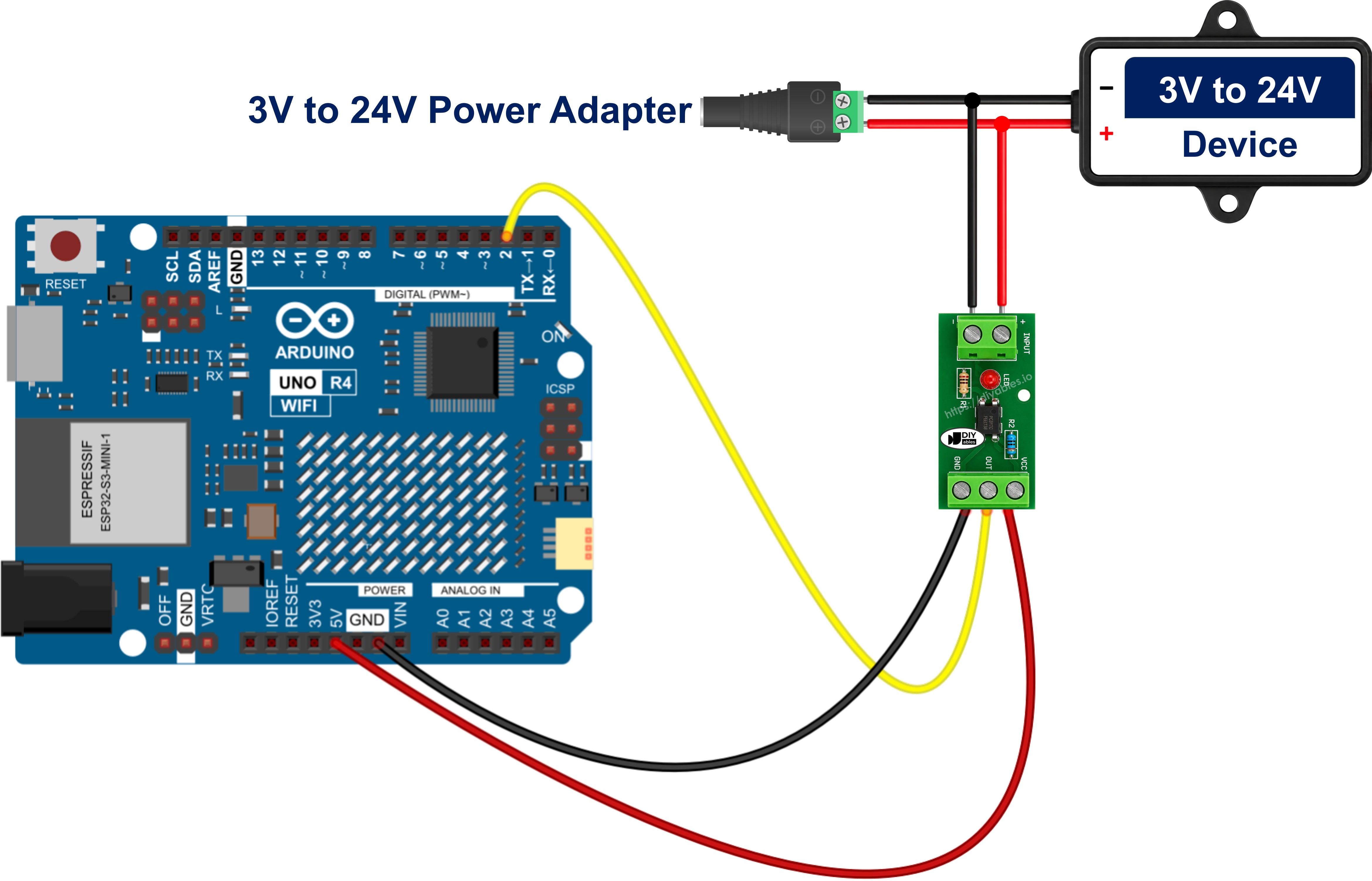
This image is created using Fritzing. Click to enlarge image
See The best way to supply power to the Arduino Uno R4 and other components.
- Wiring diagram for the Arduino UNO R4 and the bare PC817 chip, for the optional build described at the end of this guide: the 12V signal reaches pin 1 through a 1 kohm resistor (use 2.2 kohm for a 24V signal), pin 2 goes back to the ground of the 12V circuit, pin 4 goes to pin 2 of the Arduino UNO R4, and pin 3 goes to GND on the Arduino UNO R4.
Connecting the PC817 in Parallel With the Device You Want to Monitor
Take the gate operator as the worked example. Its controller sends 12V down a pair of wires to the gate motor relay whenever the gate is driven, and the Arduino UNO R4 is there to notice. The module input belongs across those two wires, in parallel with the device, sitting where a voltmeter would sit. It never goes into the wire.
WARNING
Do NOT put the PC817 input in series with the device. In series, the whole load current of the gate motor, the relay coil or the lamp has to travel through an internal LED rated for 20 mA, and the PC817 is destroyed the moment the device is switched on. Across the device, in parallel — never in line with it.
Nothing in the existing gate wiring is cut or rerouted. Three connections are added, and that is the whole job:
- The switched positive terminal of the device to the IN+ screw terminal of the module — no series resistor of your own, since the module already carries the one its variant is built around
- The negative or return terminal of that same device to the IN- screw terminal
- The output side stays exactly as it already is: OUT to pin 2 of the Arduino UNO R4, VCC to 5V, GND to GND
The tap costs only the small input-LED current the module is designed to draw. Beside the amps a gate motor, a relay coil, a valve or a lamp pulls, that is nothing, so the device carries on behaving exactly as it did before it was tapped. The measurement is read-only.
Three details decide whether the tap works on the first try:
- Polarity is not optional. The input side is an LED, and an LED conducts in one direction only. Wire IN+ and IN- the wrong way round and nothing breaks — the module simply never turns on, its status LED stays dark, and the sketch reports IDLE forever. Meter the tap and establish which side is positive before wiring it.
- An inductive load needs a clamp diode. A gate motor, a relay coil, a contactor, a solenoid or a valve throws a large reverse-voltage spike when its supply is cut, and the PC817 input LED is rated for only 6V in reverse. An ordinary diode fitted in reverse-parallel straight across the IN+ and IN- terminals — diode cathode to IN+, diode anode to IN- — absorbs it. In normal operation that diode is reverse-biased and does nothing whatsoever; on a spike it conducts and clamps the reverse voltage to well under a volt. A 1N4148 is enough for a small tap, a 1N4007 for a heavier one.
- A leaky solid-state output fools the tap. Some PLC transistor outputs, triac outputs and LED-lamp drivers pass a small current even while switched off. Enough of that leakage partially lights the module's input LED, and the sketch then insists the device is on while it is plainly off. The giveaway is a reading that never falls back to IDLE, with the status LED glowing faintly. Fit a bleeder resistor of roughly 4.7 kohm to 10 kohm across the IN+ and IN- terminals, so the leakage runs through the resistor instead of through the LED.
One last restriction: the module input is a single LED, so it answers to one polarity and to DC only. Sensing an AC line calls for an optocoupler whose input stage carries two back-to-back LEDs instead.
Knowing Whether the Device Is Actually Running
Sitting in parallel with the device is what makes the reading honest. The pin does not follow one particular button or one particular controller output — it follows the power the device is actually being fed. A gate opened from the handheld remote, from the wall switch or from a key switch looks identical to the sketch, because the sketch is watching the motor rather than the trigger. Just as usefully, a gate that was commanded to open but received nothing leaves the pin at IDLE, and that silence is itself the fault report.
That is what turns a one-line digital read into something worth logging: run-hour totals for the gate motor, an alert when an opening lasts longer than the twenty seconds it normally takes, an idle-time record for a machine, or a plain "did it actually start?" check made a few seconds after the command went out.
One honest limitation belongs with all of that: the PC817 reports that the device is energised, not that it is working — a seized motor or a burnt-out heater element still draws power on that line and still reads as LIVE.
Optional: Building the Same Input From the Bare PC817 Chip
Prefer to solder your own? Then the variant choice becomes a resistor choice: you fit the resistor the module would have carried.
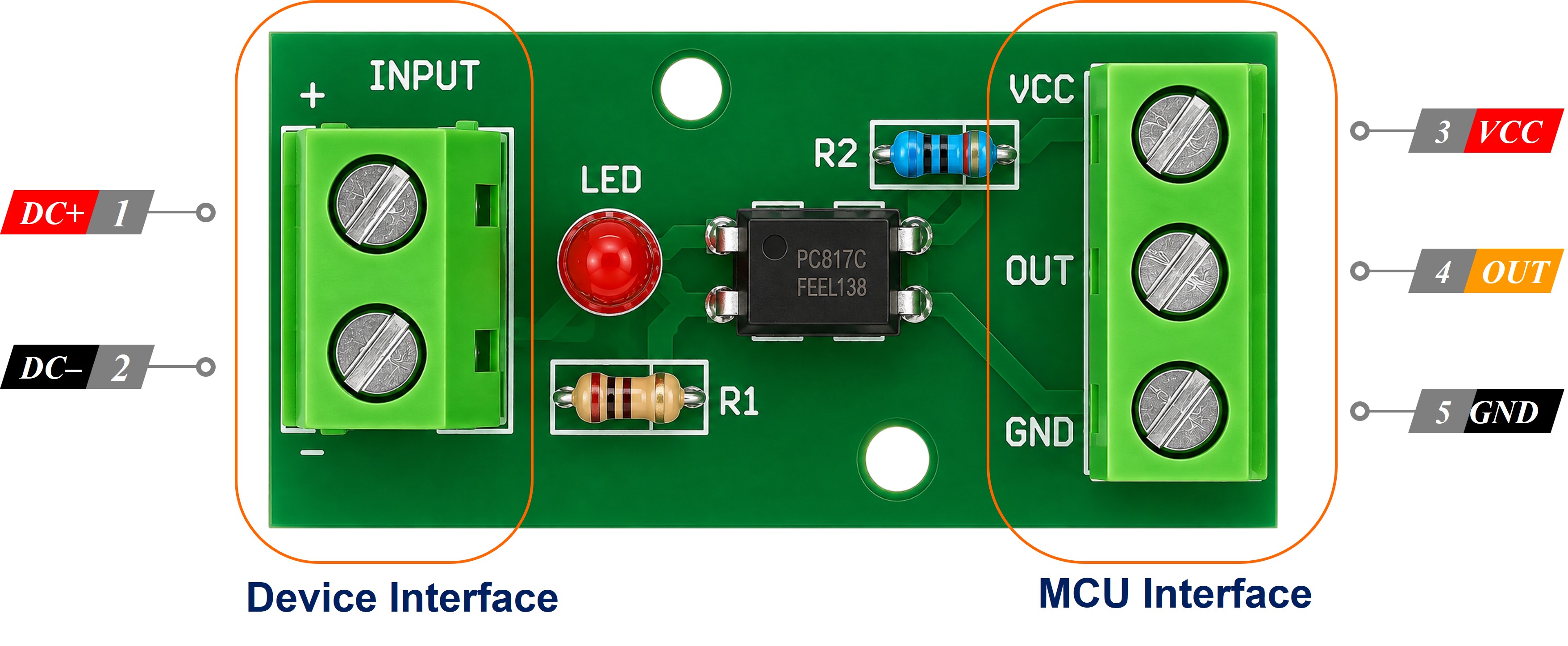
The chip is a 4-pin DIP, with pin 1 marked by a dot or a notch.
- Pin 1 - Anode (A): input LED anode, fed through the series resistor.
- Pin 2 - Cathode (K): input LED cathode, to the external circuit's ground, NOT to Arduino UNO R4 GND.
- Pin 3 - Emitter (E): output side, to GND on the board.
- Pin 4 - Collector (C): output side, to pin 2 of the Arduino UNO R4.
Size the resistor for about 10 mA of LED current using R = (Vin - 1.2) / 0.01:
| Input voltage | Resistor |
|---|---|
| 3.3V | 220 ohm |
| 5V | 390 ohm |
| 12V | 1 kohm |
| 24V | 2.2 kohm, in a 1/2 W part |
Swap the resistor whenever the input voltage changes. The rest of this page — parallel tap, clamp diode, bleeder, separate grounds — applies unchanged, and with the internal pull-up this build really is active-LOW, so leave MODULE_ACTIVE_LOW at true.
How To Program
- Name the pin the module OUT line goes to.
- Turn that pin into a pulled-up input with pinMode().
- Read the pin with digitalRead().
- Turn that raw level into a yes/no answer through the one constant that describes your module.
- Print it, or act on it.
Arduino UNO R4 Code - PC817 Optocoupler
No library is needed. Reading a PC817 is plain digital input reading.
Detailed Instructions
Follow these instructions step by step:
- If this is your first time using the Arduino Uno R4 WiFi/Minima, refer to the tutorial on setting up the environment for Arduino Uno R4 WiFi/Minima in the Arduino IDE.
- Check that the module variant on your bench matches the voltage of the line you are about to tap.
- Wire the module to the Arduino UNO R4 as shown in the diagram, keeping the 12V ground away from the board GND.
- Connect the Arduino Uno R4 board to your computer using a USB cable.
- Launch the Arduino IDE on your computer.
- Select the appropriate Arduino Uno R4 board (Arduino Uno R4 WiFi or Arduino Uno R4 Minima) and COM port.
- Copy the code above and open it in the Arduino IDE.
- Click the Upload button in the Arduino IDE to transfer the code to the Arduino UNO R4.
- Open the Serial Monitor.
- Switch the 12V line on and off a few times.
- Check the result on the Serial Monitor.
If the readings come out exactly backwards — LIVE at rest and IDLE while the line is energised — your module inverts on-board, so set MODULE_ACTIVE_LOW to false and upload again. If it reports LIVE with nothing wired to the input side at all, check that GND really reaches the module and that the pin is set to INPUT_PULLUP. If it never reports LIVE, confirm the input polarity and that the module variant matches that line's voltage. To measure that external line directly instead of only detecting it, see the Arduino UNO R4 - Measure Voltage tutorial.