
Arduino Nano ESP32 - MAX6675 Thermocouple Module
Every other temperature tutorial in this series - the DHT11/DHT22, the DS18B20, the TMP36 - shares the same weakness: none of them can survive being dropped into anything actually hot. Their plastic packages and silicon dies start to give up well under 150°C, which rules out roasting a batch of coffee beans, watching over a pottery kiln, or checking the flue temperature on a wood stove.
The fix is a completely different sensing technology called a thermocouple, paired with a small breakout board that turns its output into a number the Arduino Nano ESP32 can read. This tutorial covers wiring and programming the MAX6675 thermocouple module with the Arduino Nano ESP32.
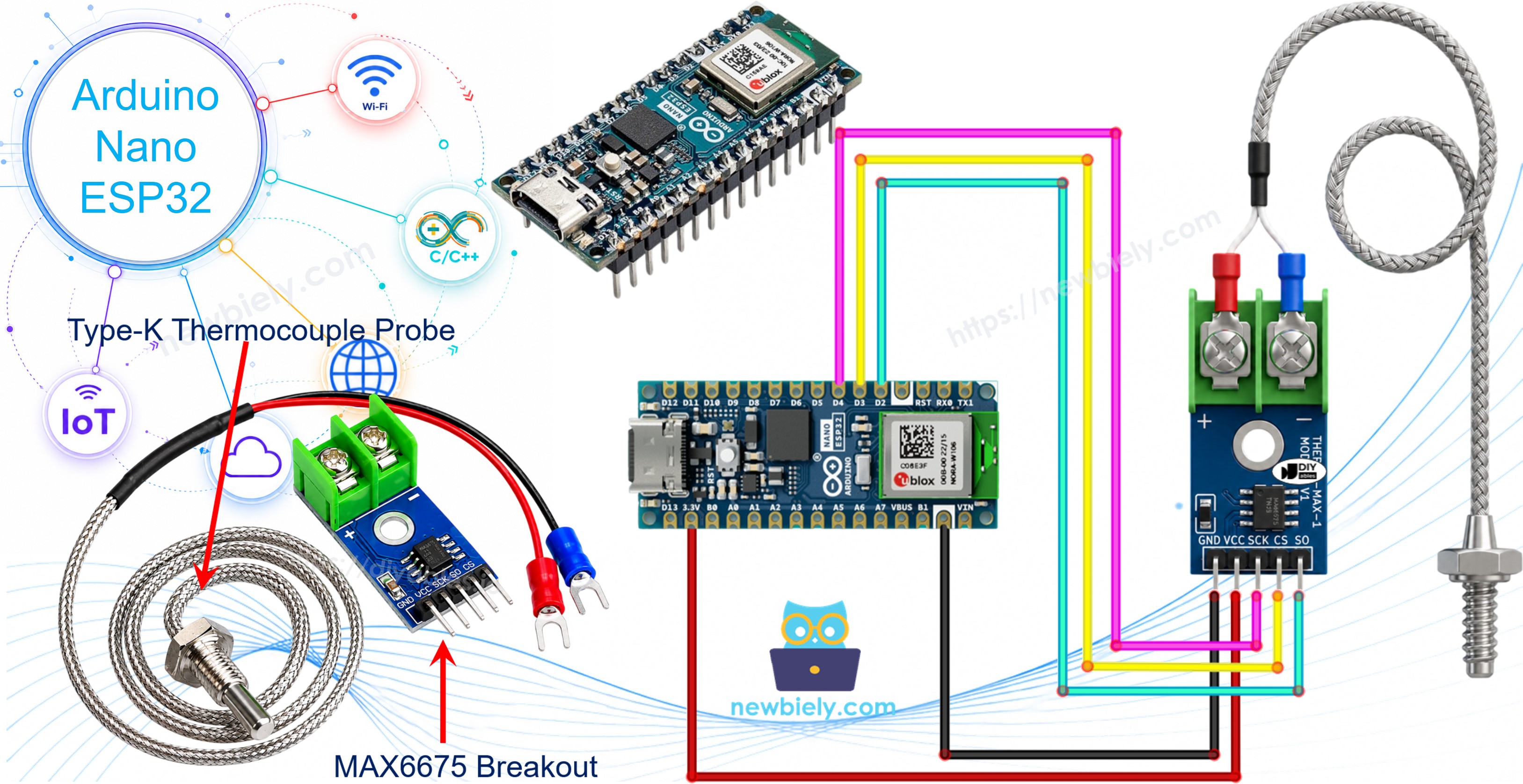
Hardware Preparation
Or you can buy the following kits:
| 1 | × | DIYables Sensor Kit (18 sensors/displays) |
Additionally, some of these links are for products from our own brand, DIYables .
Overview of MAX6675 Thermocouple Module
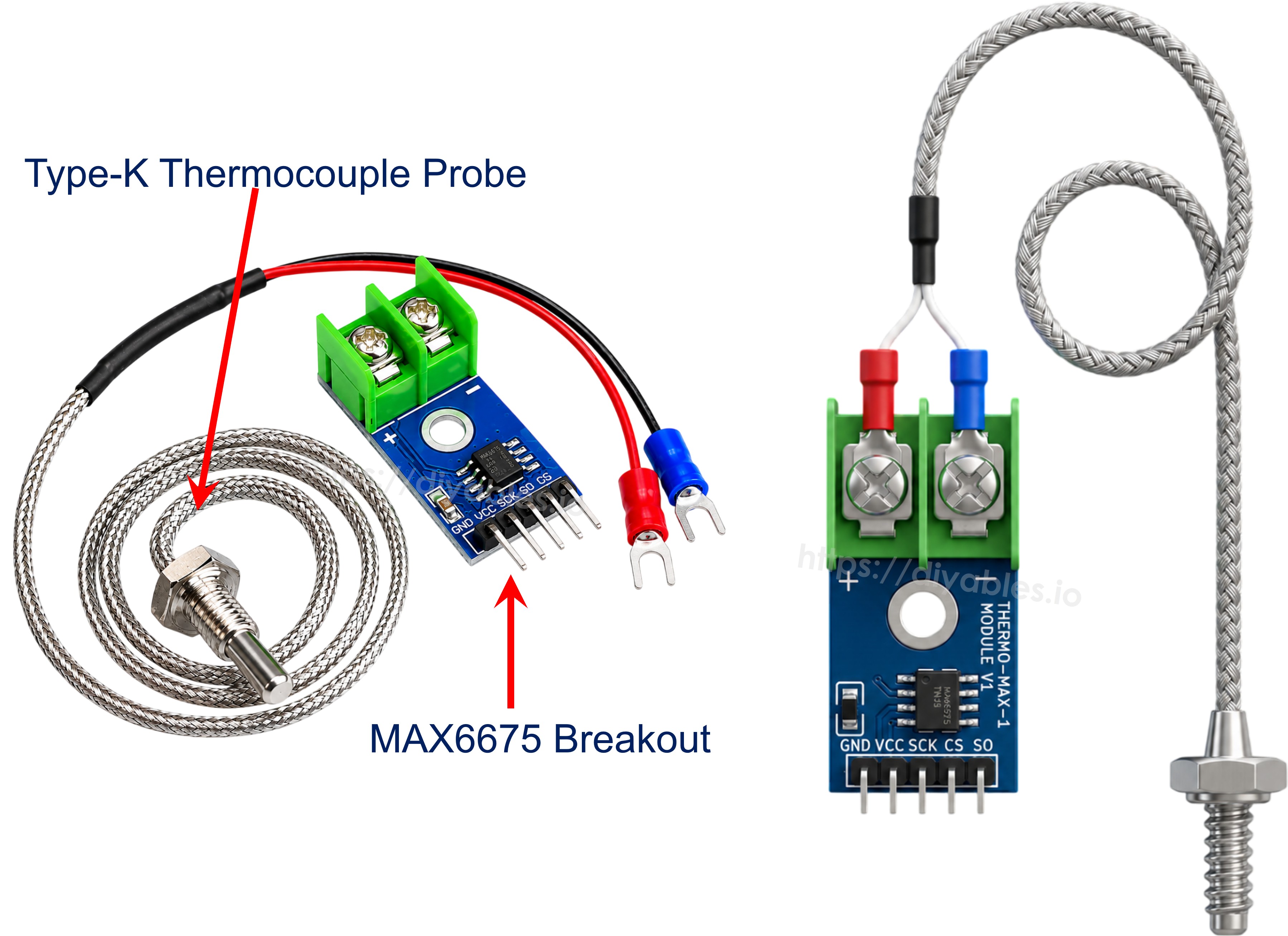
What ships as "a MAX6675 module" is really two things bundled together: a small breakout board built around the MAX6675 chip, and a Type-K thermocouple probe wired into it.
What Is a Thermocouple?
Strip away the marketing, and a thermocouple is nothing more than two dissimilar metal wires welded together at one tip, called the hot junction. Heat that junction and a small voltage appears across the wires, growing or shrinking as the temperature changes. There's no chip, no silicon, nothing to melt - which is exactly why a thermocouple can be pushed into places that would instantly kill a normal sensor.
Thermocouples come in several flavors (J, K, E, T, and others), named after the metal pairing used. Type-K - made from Chromel and Alumel - is the one you'll run into most often, and it comfortably spans roughly -328°F to +2300°F.
On its own, though, that millivolt-level signal is awkward to work with. It needs amplifying, linearizing, and converting into an actual temperature figure before an Arduino Nano ESP32 can do anything useful with it - and that conversion job belongs to the MAX6675.
MAX6675 Module Pinout
The breakout constantly samples the probe's tiny voltage, feeds it through a 12-bit analog-to-digital converter, and hands the finished reading to the Arduino Nano ESP32 over a 3-wire read-only link:
- VCC: power input, accepts 3.0V to 5.5V.
- GND: ground reference.
- SCK: serial clock, driven by the Arduino Nano ESP32 to shift each reading out.
- CS: chip select - the Arduino Nano ESP32 pulls this low whenever it wants to take a reading.
- SO: serial data output, the module's MISO line, carrying the 12-bit result back to the Arduino Nano ESP32. There is no MOSI pin at all, since the chip never needs data sent to it.
Along the opposite edge sits a 2-pin screw terminal for the probe: the red wire clips into +, the blue wire into -.
The probe bundled with the module runs about 18 inches long and is only rated for 0°C to 80°C, even though the MAX6675 chip itself can digitize readings anywhere from 0°C up to 1024°C. Measuring anything hotter than 80°C means fitting a higher-temperature-rated Type-K probe in its place.
Quick specs:
- Operating Voltage: 3.0V - 5.5V
- Digitized Range: 0 - 1024°C (bundled probe limited to 0-80°C)
- Accuracy: ±3°C
- Resolution: about 0.25°C
Wiring Diagram
The Arduino Nano ESP32's own logic runs at 3.3V, and the MAX6675 module is happy anywhere between 3.0V and 5.5V, so power VCC from the board's 3V3 pin and tie GND to GND. Pick any three spare digital pins for SCK, CS, and SO, then clip the probe's red and blue wires into the module's + and - terminals.
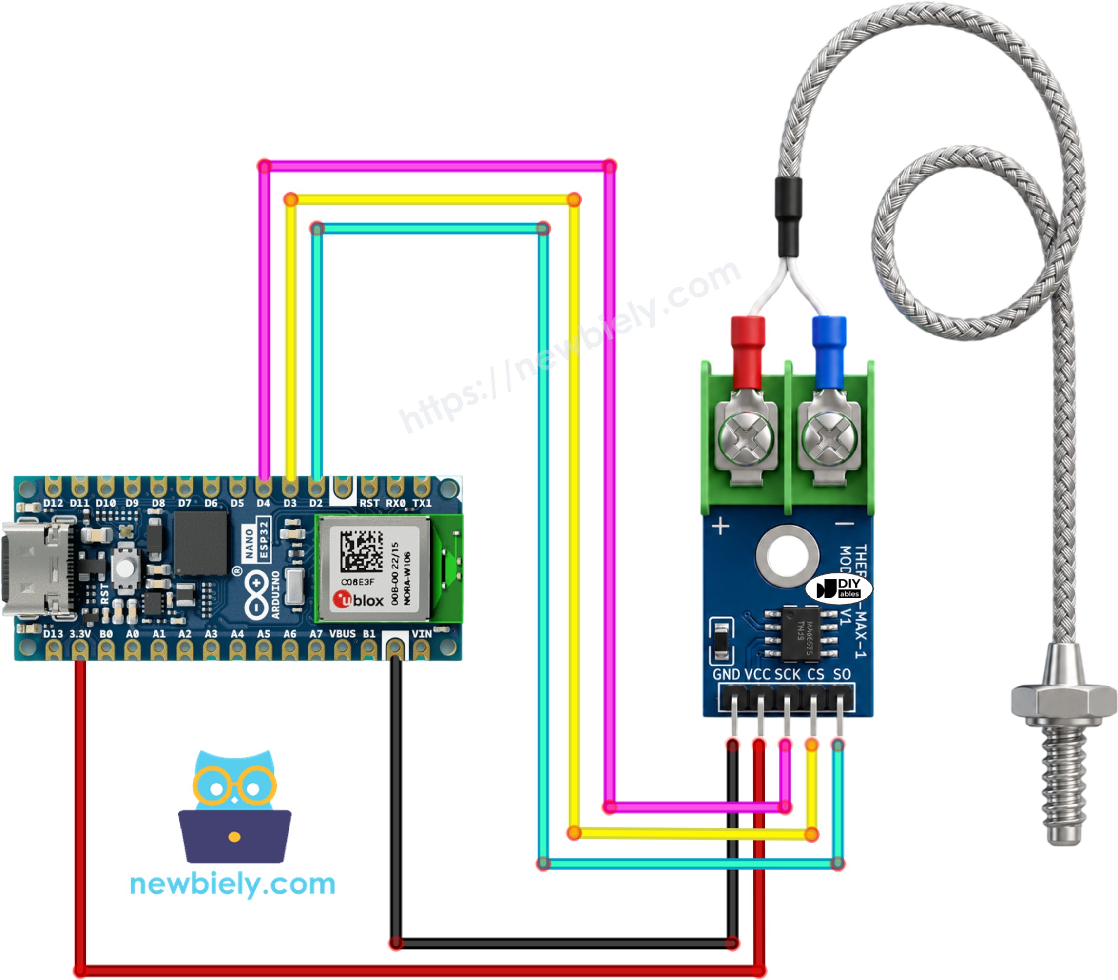
This image is created using Fritzing. Click to enlarge image
Wiring table of MAX6675 Module and Arduino Nano ESP32
| MAX6675 Module | Arduino Nano ESP32 |
|---|---|
| VCC | → 3V3 |
| GND | → GND |
| SCK | → D4 |
| CS | → D3 |
| SO | → D2 |
Arduino Nano ESP32 Code
Detailed Instructions
To get started with Arduino Nano ESP32, follow these steps:
- If you are new to Arduino Nano ESP32, refer to the tutorial on how to set up the environment for Arduino Nano ESP32 in the Arduino IDE.
- Wire the MAX6675 module to the Arduino Nano ESP32 according to the table and diagram above.
- Connect the Arduino Nano ESP32 board to your computer using a USB cable.
- Launch the Arduino IDE on your computer.
- Select the Arduino Nano ESP32 board and its corresponding COM port.
- Open the Library Manager by clicking on the Library Manager icon on the left navigation bar of Arduino IDE
- Type "MAX6675" on the search box, then look for the MAX6675 library by Adafruit.
- Click Install button to install the library.
- Search for MAX6675 library created by Adafruit and click the Install button.
- Copy the above code and paste it to Arduino IDE.
- Compile and upload code to Arduino Nano ESP32 board by clicking Upload button on Arduino IDE.
- Touch the thermocouple tip to whatever you want to measure - a mug of hot water works well for a first test.
- Open Serial Monitor to see the readings roll in.
※ NOTE THAT:
If the Serial Monitor keeps printing the same value or something clearly wrong, recheck the SCK/CS/SO wiring against the pins used in the sketch, and make sure the probe's red and blue leads are actually clamped inside the terminal block rather than just touching it.
Code Explanation
The sketch starts by pulling in the MAX6675 library header, which takes care of the low-level communication with the chip.
Three pin numbers are then defined for the connection between the Arduino Nano ESP32 and the module's clock, chip-select, and data-out lines.
A MAX6675 object named thermocouple is created next, telling the library which pin plays which role.
setup() opens the Serial connection and pauses briefly, giving the module a moment to settle before the sketch asks it for its first reading.
Inside loop(), two library functions do all the work: thermocouple.readCelsius() and thermocouple.readFahrenheit() each trigger a fresh conversion on the chip and return the result in the requested unit.
Both figures are then printed on a single Serial Monitor line, followed by a one-second delay, matching the pace at which the MAX6675 can actually produce new conversions.