Arduino Nano ESP32 - Web Apps Web Digital Pins
Overview
This tutorial covers the DIYablesWebDigitalPinsPage class from the DIYables ESP32 WebApps Library. The page presents each registered pin as a button in the browser. Output pins can be toggled; input pins display their current state. Pin configuration is done entirely in the sketch — the browser reflects whatever mode the sketch defines.
What This Tutorial Covers
- Enabling individual pins as WEB_PIN_OUTPUT or WEB_PIN_INPUT
- Reading output state changes from the browser via a callback
- Supplying input pin values to the browser via a read callback
- Pushing state updates to connected browsers from the sketch
Hardware Preparation
Or you can buy the following kits:
| 1 | × | DIYables Sensor Kit (18 sensors/displays) |
Additionally, some of these links are for products from our own brand, DIYables .
Steps
Follow these instructions step by step:
- If this is your first time using the Arduino Nano ESP32, refer to the tutorial on setting up the Arduino Nano ESP32 development environment.
- Connect the Arduino Nano ESP32 board to your computer using a USB cable.
- Launch the Arduino IDE on your computer.
- Select the appropriate board (e.g. Arduino Nano ESP32) and COM port.
- Navigate to the Libraries icon on the left bar of the Arduino IDE.
- Search "DIYables ESP32 WebApps", then find the DIYables ESP32 WebApps Library by DIYables
- Click Install button to install the library.
- Search for DIYables ESP32 WebApps created by DIYables and click the Install button.
- You will be asked for installing some other library dependencies
- Click Install All button to install all library dependencies.
- On Arduino IDE, Go to File Examples DIYables ESP32 WebApps WebDigitalPins example, or copy the above code and paste it to the editor of Arduino IDE
- Update the WiFi credentials in the sketch:
- Click Upload button on Arduino IDE to upload code to Arduino Nano ESP32
- Open the Serial Monitor
- The Serial Monitor output should resemble the following:
- If nothing appears, press the reset button on the board.
- Enter the IP address from the Serial Monitor into a browser on the same network.
- Example: http://192.168.0.2
- The home page displays a card for the digital pins application:
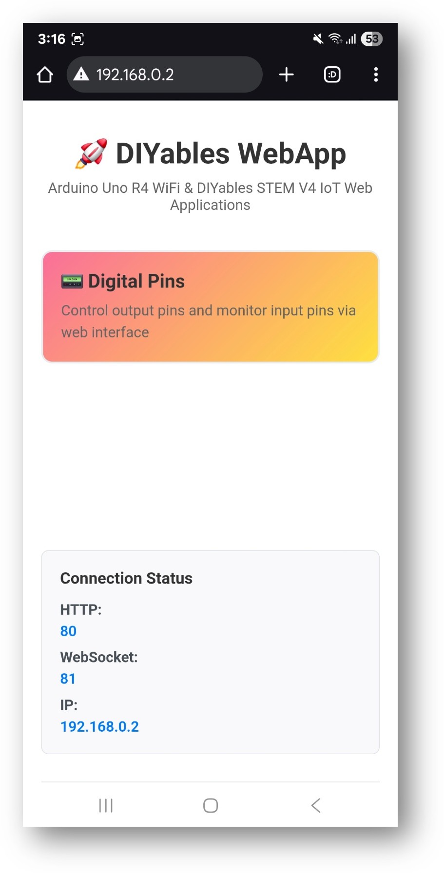
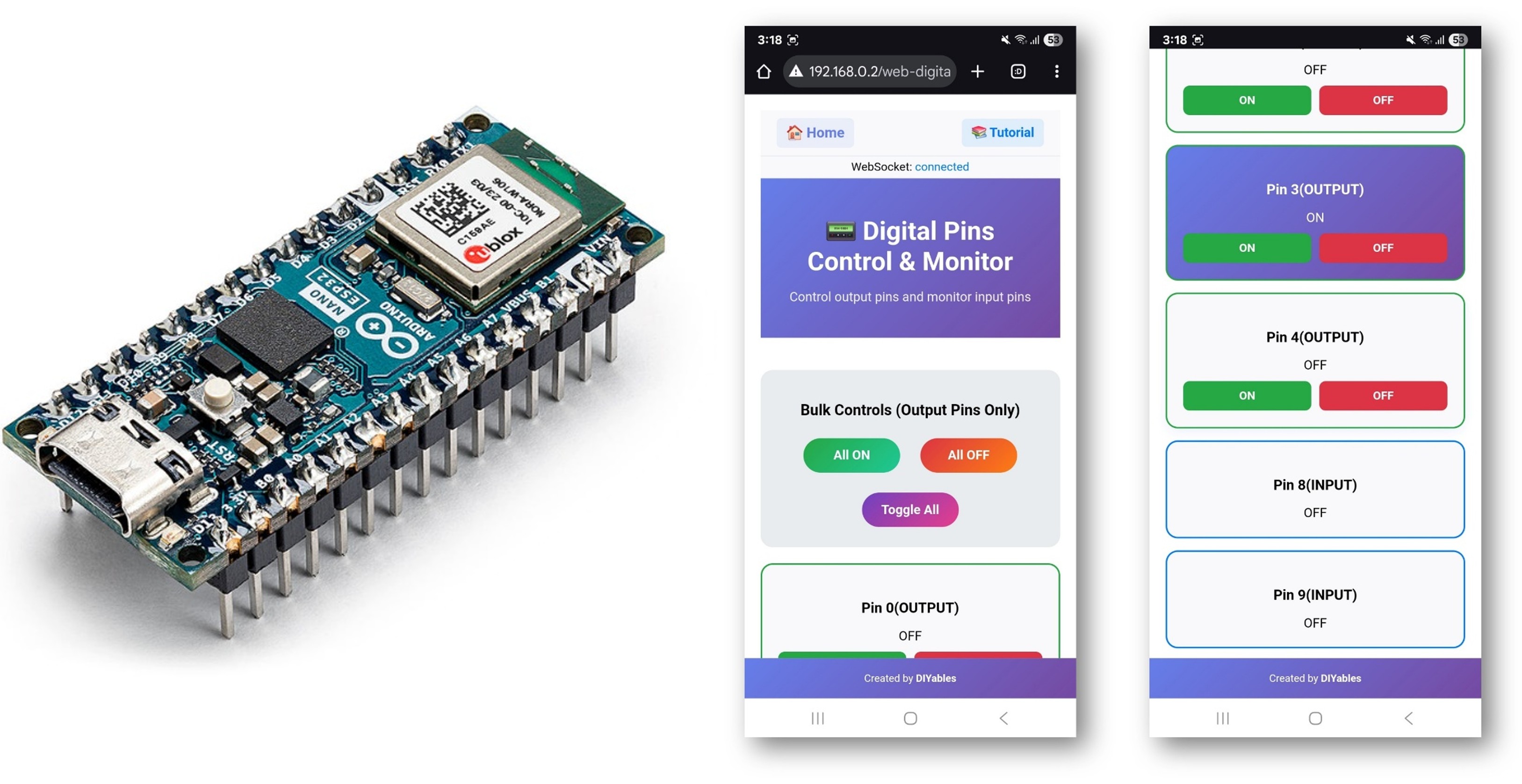
- Select the Digital Pins card to open the pin control page:
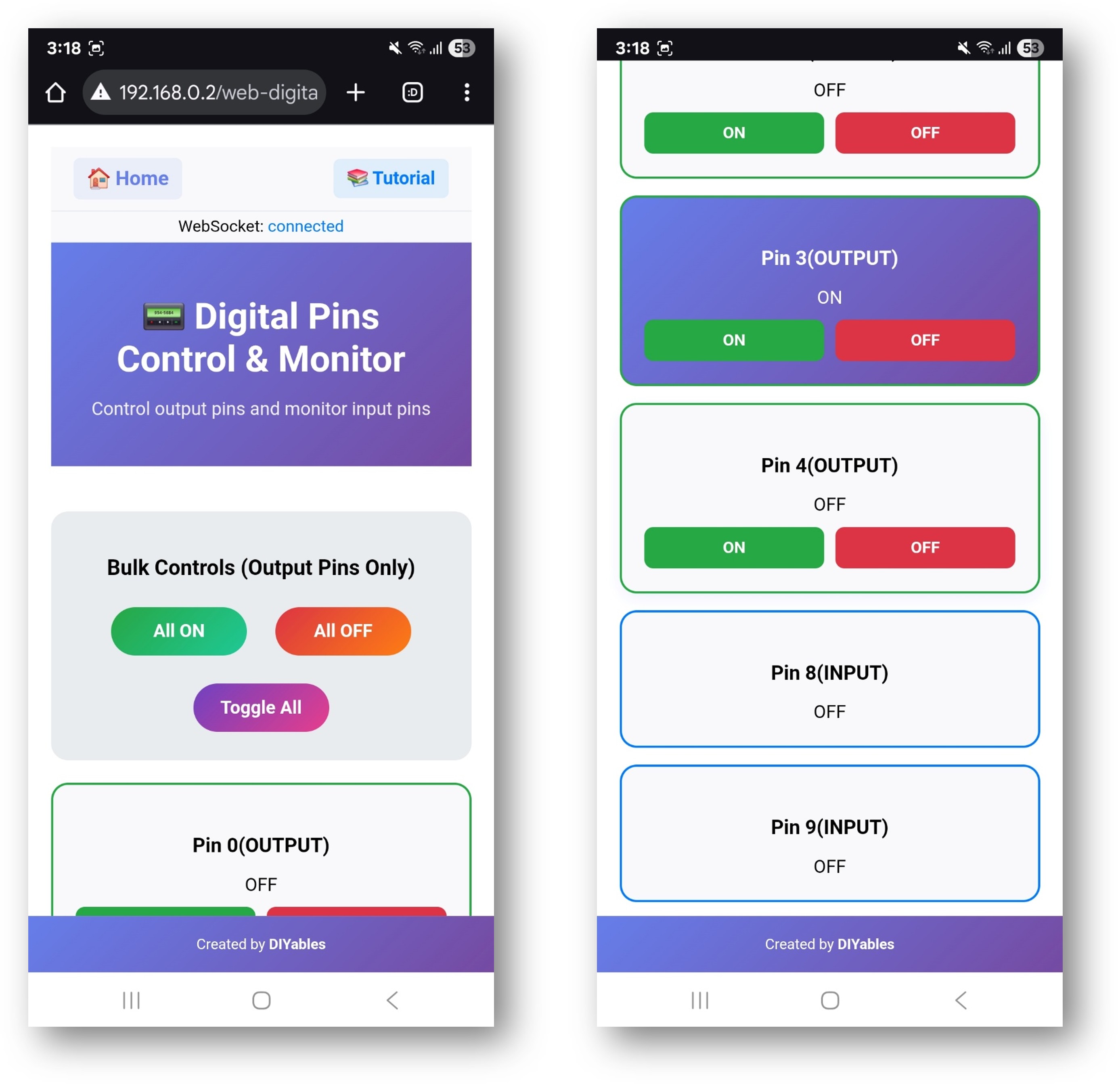
- The page is also accessible directly at http://192.168.0.2/web-digital-pins.
- Toggle output pins by clicking the corresponding buttons. Pin 13 (built-in LED) should respond immediately.
Pin Configuration Methods
Pins must be registered before webAppsServer.begin(). Three patterns are supported:
Enabling Individual Pins
Enabling a Range of Output Pins
Enabling All Pins
Callbacks
Write Callback (Output Pins)
Called when the browser toggles an output pin:
Read Callback (Input Pins)
Called when the browser requests an input pin's current state:
Pushing State from the Sketch
When an input changes state outside of a browser request, push the update manually:
Web Interface Controls
- Pin button: Click to toggle an output pin HIGH or LOW. Green indicates HIGH; red indicates LOW.
- All ON: Sets all registered output pins to HIGH.
- All OFF: Sets all registered output pins to LOW.
- Toggle All: Inverts the current state of all output pins.
Input pins display their current state without a toggle button — the browser refreshes them periodically via WebSocket.
Troubleshooting
Pin state does not change when clicked
- Verify onPinWrite callback is registered before webAppsServer.begin()
- Confirm the pin is registered with WEB_PIN_OUTPUT
- Check the Serial Monitor for incoming WebSocket messages
Input pin shows wrong state
- Confirm onPinRead callback is registered
- Add a pull-up or pull-down resistor to avoid floating inputs
- Check digitalRead() returns the expected value in the callback
Page not accessible
- Check the IP address printed in the Serial Monitor
- Make sure port 80 is open on the network
- Both the board and browser device must be on the same 2.4 GHz WiFi network