
Arduino Nano ESP32 - SW-420 Vibration Sensor
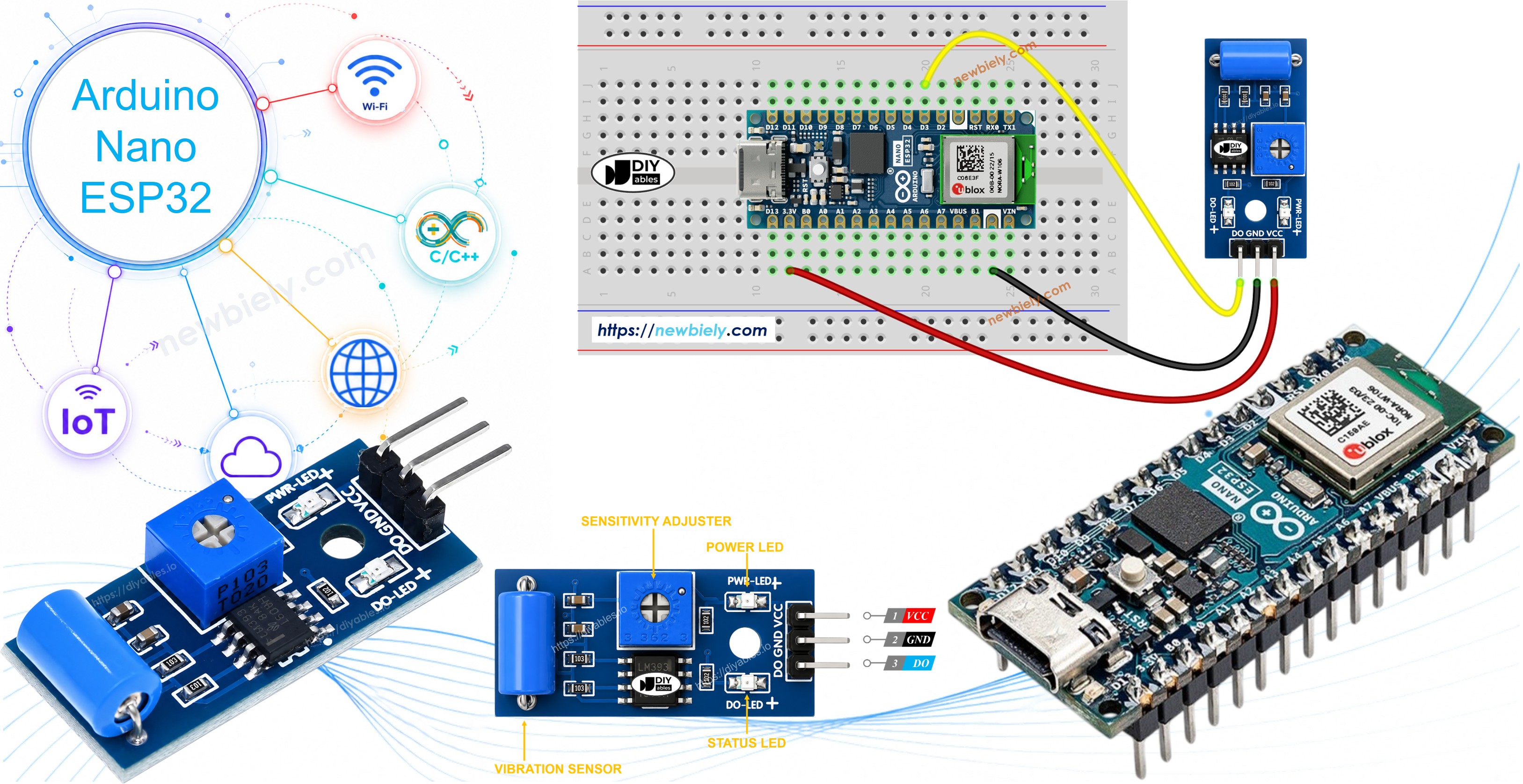
The SW-420 vibration sensor module can catch sudden shocks or shaking that occur around it, making it a handy building block for knock detectors, impact alarms, or any project that needs to notice a bump.
In this guide, we will learn how to use the SW-420 vibration sensor with the Arduino Nano ESP32. In detail, we will learn:
- How to wire the SW-420 vibration sensor module to the Arduino Nano ESP32.
- How to write a sketch for the Arduino Nano ESP32 that reports vibration events over Serial.
Once the basic sketch is working, you can adapt it to sound a buzzer, flash an LED, or send a notification whenever the module picks up a shock.
Hardware Preparation
Or you can buy the following kits:
| 1 | × | DIYables Sensor Kit (18 sensors/displays) |
Additionally, some of these links are for products from our own brand, DIYables .
Overview of SW-420 Vibration Sensor
The SW-420 vibration sensor module reacts to shaking, knocking, or shock in its surroundings. Inside the module sits a small spring-based switch positioned next to a metal contact; an onboard LM393 comparator watches this switch and produces a clean digital signal the moment vibration disturbs it. A trimmer potentiometer on the board lets you dial in how much shaking is needed before it reports a trigger.
Pinout
The SW-420 vibration sensor module has three pins:
- VCC pin: connect to VCC (3.3V to 5V)
- GND pin: connect to GND (0V)
- DO pin: digital output pin, LOW while the module is at rest and HIGH the moment vibration or shock is picked up. Wire this pin to an input pin on the Arduino Nano ESP32.
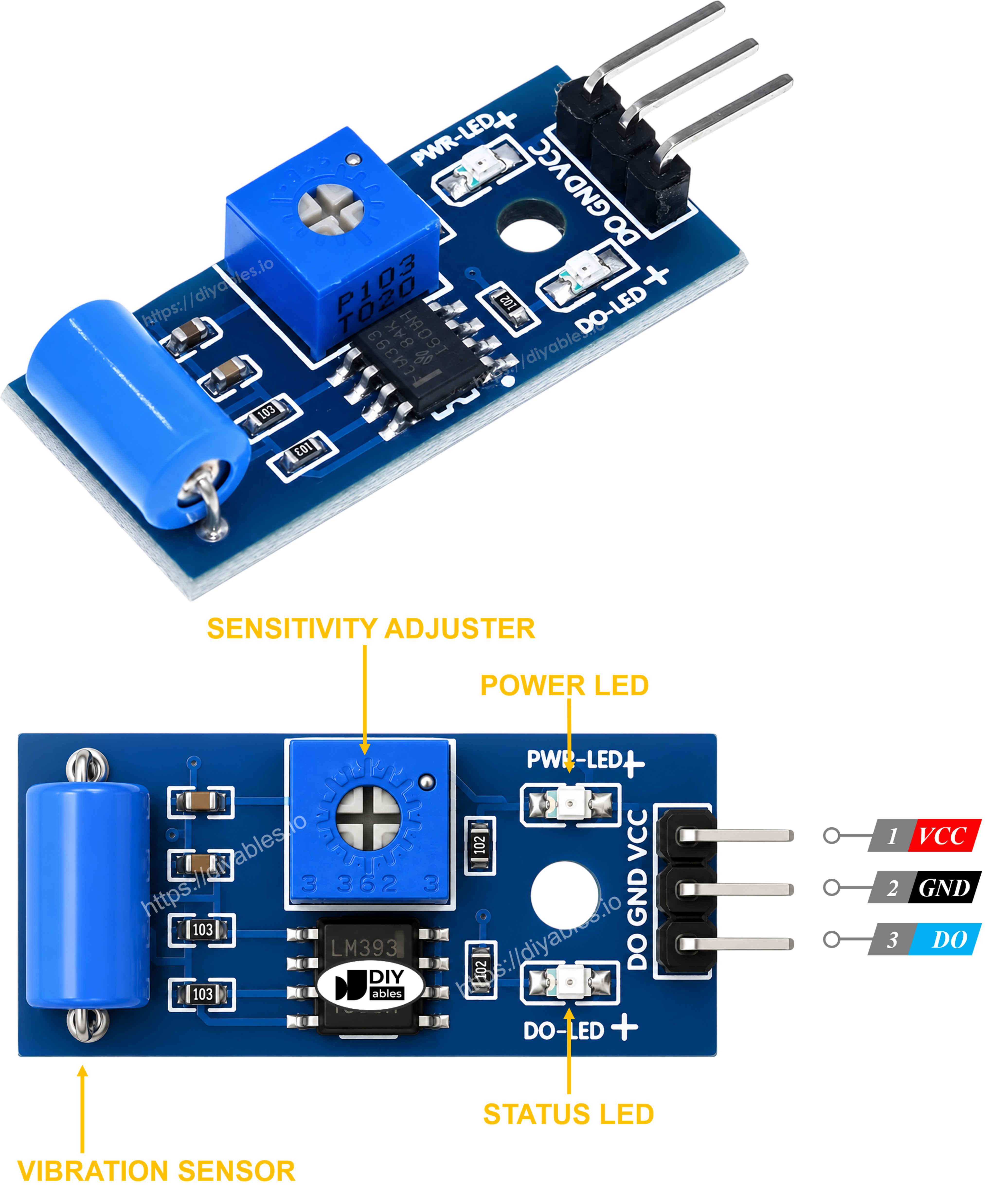
Two onboard LEDs help with a quick visual check:
- A power LED stays lit whenever the module is powered.
- A trigger LED lights up together with the DO pin whenever vibration is detected.
How It Works
The output pin follows the state of the internal switch:
- At rest, the spring switch stays open, so the comparator holds the output pin LOW.
- When a shock or vibration disturbs the switch, it momentarily closes, and the comparator drives the output pin HIGH.
Wiring Diagram
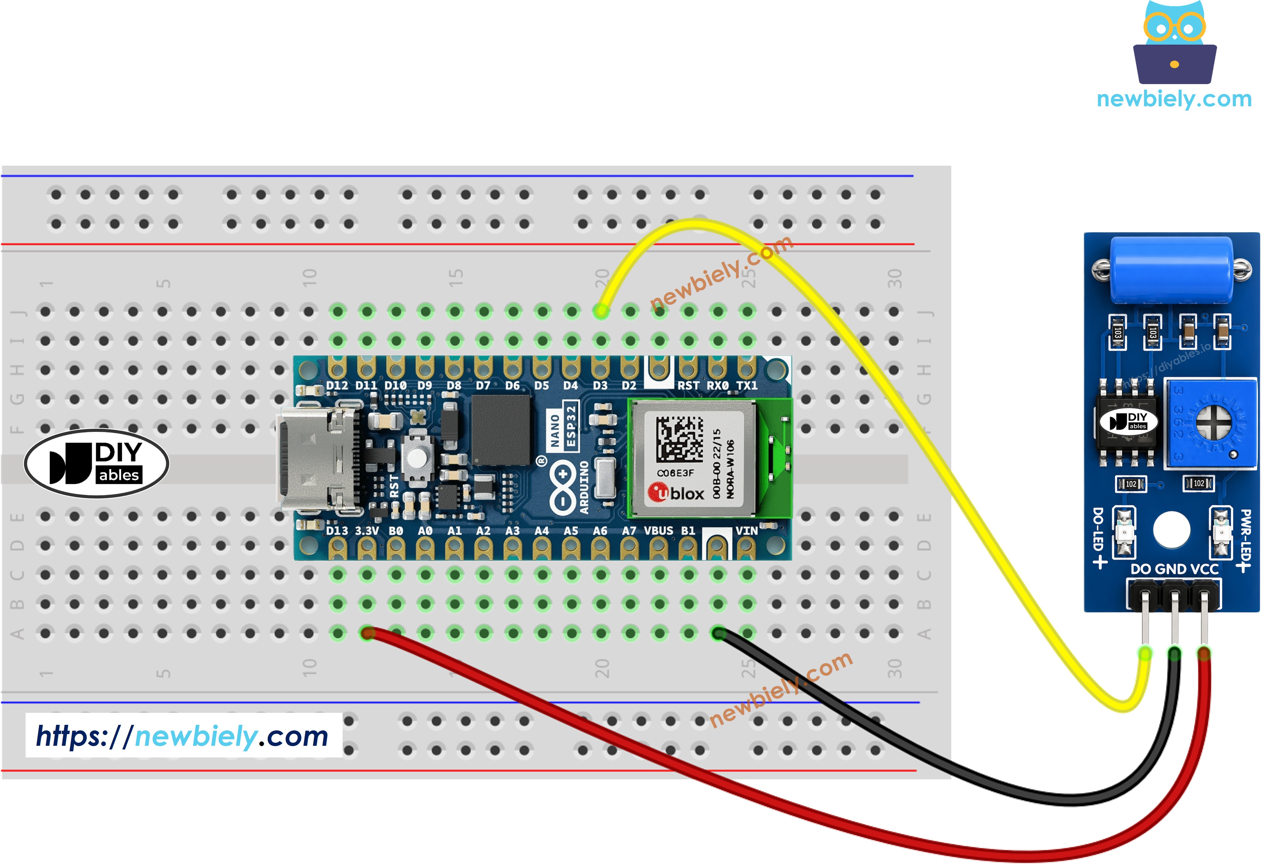
This image is created using Fritzing. Click to enlarge image
How To Program For SW-420 Vibration Sensor
- Configure the pin connected to the sensor's DO output as a digital input using pinMode(). For example, pin D3
- Read the sensor state with digitalRead().
Arduino Nano ESP32 Code - Detecting vibration
Detailed Instructions
Follow these instructions step by step:
- If this is the first time you use Arduino Nano ESP32, see how to setup environment for Arduino Nano ESP32 on Arduino IDE.
- Wire the components according to the diagram above.
- Copy the code above into the Arduino IDE.
- Select the correct board and COM port, then click the Upload button.
- Give the sensor module a light tap or shake it gently.
- Open the Serial Monitor to view the reported events.
From here, you can extend the sketch to light an LED, sound a buzzer, or push a notification whenever the SW-420 reports a shock. Check the tutorials linked at the bottom of this page for ideas on where to take it next.
Troubleshooting
If the SW-420 vibration sensor does not behave as expected, work through these checks:
- Adjust the sensitivity: Turn the onboard potentiometer to raise or lower the amount of shaking needed to trigger the output.
- Isolate ambient vibration: Mount the module away from motors, fans, or other sources of constant background shaking that can cause false triggers.
- Check the wiring: Confirm the VCC, GND, and DO pins are connected to the correct pins on the Arduino Nano ESP32.
- Check the power supply: Make sure the module is receiving a steady 3.3V to 5V supply.