
Arduino UNO R4 - Slide Switch
In this guide, we will learn how to use the DIYables SS12D10 mini slide switch with the Arduino UNO R4. Think of a mute option for a buzzer, a choice between Celsius and Fahrenheit, or a "debug mode" that prints extra messages. Each of these is a setting that should stay as you left it. A push button forgets its state as soon as you lift your finger, but a slide switch keeps it. In detail, we will learn:
- What the three pins of the SS12D10 do, and how the handle joins them.
- How to wire the slide switch to the Arduino UNO R4 WiFi or Minima with three wires, so no resistor is needed.
- How to print ON or OFF one time for each move of the handle, with a 50 ms debounce check.
- How to save one wire by using the internal pull-up resistor (INPUT_PULLUP).
Hardware Preparation
Or you can buy the following kits:
| 1 | × | DIYables STEM V4 IoT Starter Kit (Arduino included) | |
| 1 | × | DIYables STEM V4B IoT Starter Kit (Arduino included) | |
| 1 | × | DIYables Sensor Kit (18 sensors/displays) |
Additionally, some of these links are for products from our own brand, DIYables .
Overview of Slide Switch
The SS12D10 is a tiny switch with a sliding handle on top and three through-hole pins in a row under it. It is an SPDT switch, also called 1P2T: one common pin and two positions. The handle latches. It stays at the side where you leave it until you push it to the other side.
Inside, a small metal bridge always touches the middle pin. When you slide the handle, the bridge also touches the outer pin on the handle's side.
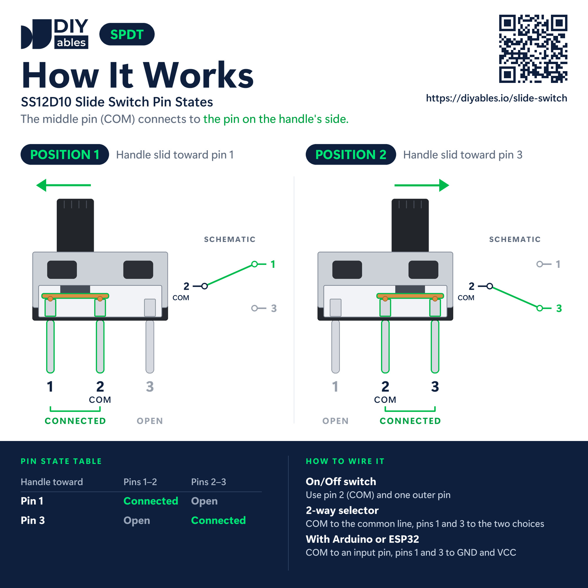
No labels are printed on the switch, but the middle pin is always COM. Here is how to use each pin in this guide:
- Pin 1 (outer pin): connect to GND (0V).
- Pin 2, COM (middle pin): connect to a digital input pin of the Arduino UNO R4. It gives out the voltage of the outer pin that the handle joins it to.
- Pin 3 (outer pin): connect to 5V.
| Handle position | Pins joined | Pin left open |
|---|---|---|
| Toward pin 1 | pin 1 and pin 2 (COM) | pin 3 |
| Toward pin 3 | pin 2 (COM) and pin 3 | pin 1 |
| Mini Slide Switch SS12D10 | |
|---|---|
| Contact type | SPDT (1P2T), 2 positions |
| Pins | 3 in a row, 4.7mm pitch, 6.9mm long |
| Handle | 5mm |
| Body size | about 12.8 x 6.7 x 18.2mm |
| Mounting | vertical, through-hole |
| Contacts | silver-plated brass |
| Contact rating | AC 125V 2A |
| Life | more than 100,000 switching cycles |
| Operating temperature | -25°C to 80°C |
The 125V 2A rating tells you what the contacts can carry. In this guide, the switch only passes a tiny signal current into an input pin, far below that limit.
Like every mechanical contact, the switch bounces for a few milliseconds when the handle moves. For that short time the pin can flip between HIGH and LOW. Our code waits 50 ms and reads again, so each move prints only one line.
Related pages for the Arduino UNO R4:
- A row of tiny slide switches in one package: Arduino UNO R4 - DIP Switch.
- A key that springs back after each press: Arduino UNO R4 - Button Module.
Wiring Diagram
Three jumper wires, no resistor: pin 1 of the switch to GND, COM to digital pin 7, and pin 3 to the 5V pin of the Arduino UNO R4. Because COM is always joined to either GND or 5V, pin 7 never floats. That is why plain INPUT mode is enough here, with no pull-up or pull-down resistor.
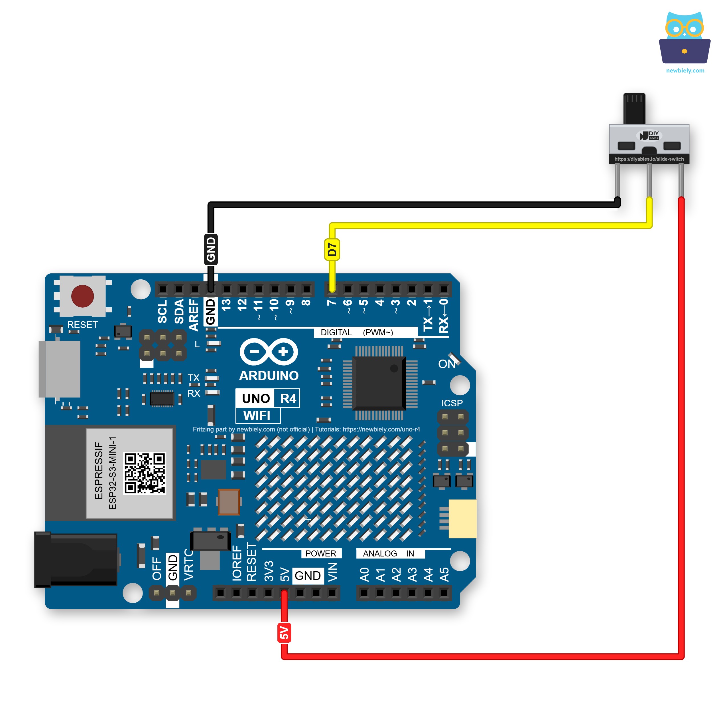
This image is created using Fritzing. Click to enlarge image
| Slide Switch Pin | Arduino UNO R4 Pin |
|---|---|
| Pin 1 | GND |
| Pin 2 (COM) | 7 |
| Pin 3 | 5V |
Want a cleaner and safer setup? Put a Screw Shield V2 or a Proto Screw Terminal Block Shield on top of the Arduino UNO R4, then tighten each wire under a screw. Each wire goes to the screw terminal of the same pin, as in the image below.
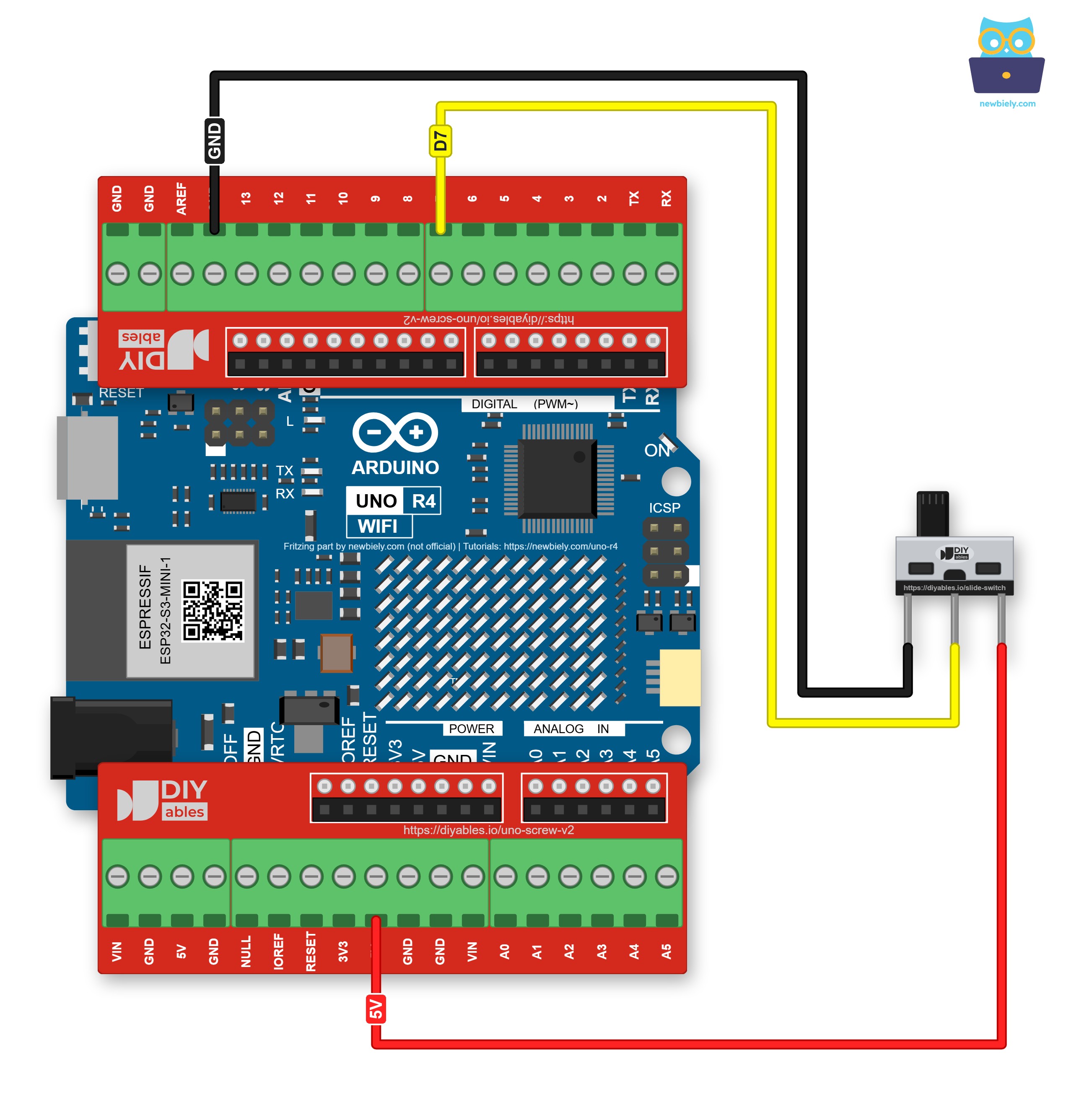
This image is created using Fritzing. Click to enlarge image
※ NOTE THAT:
- Pin 3 goes to the 5V pin, because the Arduino UNO R4 uses 5V logic. The 3.3V pin is not used in this wiring.
- Keep pin 7 as an input. Never set it to OUTPUT: the switch ties it straight to 5V or GND, and an output pin that drives the other level would be shorted.
How To Program For Slide Switch
No library is needed. The built-in Arduino functions do all the work.
- Give a name to the pin wired to COM:
- Set it as a plain input. The switch itself drives the pin, so the internal pull-up stays off:
- Read the handle position. HIGH means the handle is toward pin 3 (ON), LOW means it is toward pin 1 (OFF):
- When a new reading differs from the last one, wait 50 ms and read again. Accept the change only if it is still there.
Arduino UNO R4 Code - Slide Switch
The sketch below reports the handle position once at the start. After that, it stays quiet until the handle really moves, and then it prints the new position one time.
Detailed Instructions
Follow these instructions step by step:
- If this is your first time using the Arduino Uno R4 WiFi/Minima, refer to the tutorial on setting up the environment for Arduino Uno R4 WiFi/Minima in the Arduino IDE.
- Wire the slide switch to the Arduino UNO R4 as shown in the wiring diagram.
- Plug the Arduino UNO R4 into your computer with a USB Type-C cable.
- Launch the Arduino IDE on your computer.
- Select the appropriate Arduino UNO R4 board (e.g., Arduino UNO R4 WiFi or Arduino UNO R4 Minima) and COM port.
- Paste the code above into the Arduino IDE and click the Upload button.
- Open the Serial Monitor at 9600 baud. If the first line is missing, press the RESET button on the board once.
- Slide the handle toward pin 1, then toward pin 3, and repeat.
Four moves give four "Moved" lines. Leave the handle alone and nothing new appears, because the sketch only prints a change.
Arduino UNO R4 Code - Slide Switch with INPUT_PULLUP (2 Wires)
Short on wires, or have no free 5V pin? You can drop the wire on pin 3. The Arduino UNO R4 then uses its own internal pull-up resistor to give pin 7 a HIGH level when COM is open. Only two wires are left: pin 1 to GND and COM to pin 7.
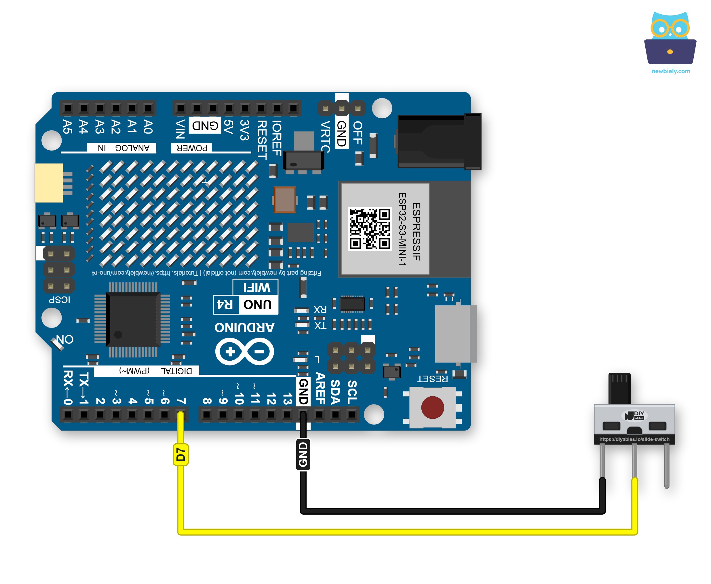
This image is created using Fritzing. Click to enlarge image
See The best way to supply power to the Arduino Uno R4 and other components.
| Slide Switch Pin | Arduino UNO R4 Pin |
|---|---|
| Pin 1 | GND |
| Pin 2 (COM) | 7 |
| Pin 3 | not connected |
With this wiring, the logic is flipped:
- Handle toward pin 1: COM is joined to GND, pin 7 reads LOW. The sketch prints ON.
- Handle toward pin 3: COM touches nothing, the pull-up holds pin 7 HIGH. The sketch prints OFF.
Detailed Instructions
- Just remove the pin 3 wire. Pin 1 and COM stay where they are.
- Paste this code into a new sketch and click Upload.
- Move the handle toward pin 1, then back toward pin 3, while you watch the Serial Monitor.
The handle sat toward pin 3 at the start, so the first line says OFF. In the 3-wire version, the same position meant ON.
Project Ideas
A few ways to put the slide switch to work with the Arduino UNO R4:
- A mute switch: a buzzer beeps for alarms only while the switch is OFF.
- A unit selector: show a temperature in Celsius or in Fahrenheit, based on the handle position.
- A mode switch on the Arduino UNO R4 WiFi: in one position the board connects to WiFi, in the other it works offline.
- A "show / hide" switch for a pattern on the built-in LED matrix of the UNO R4 WiFi.