
Arduino Nano - MAX6675 Thermocouple Module
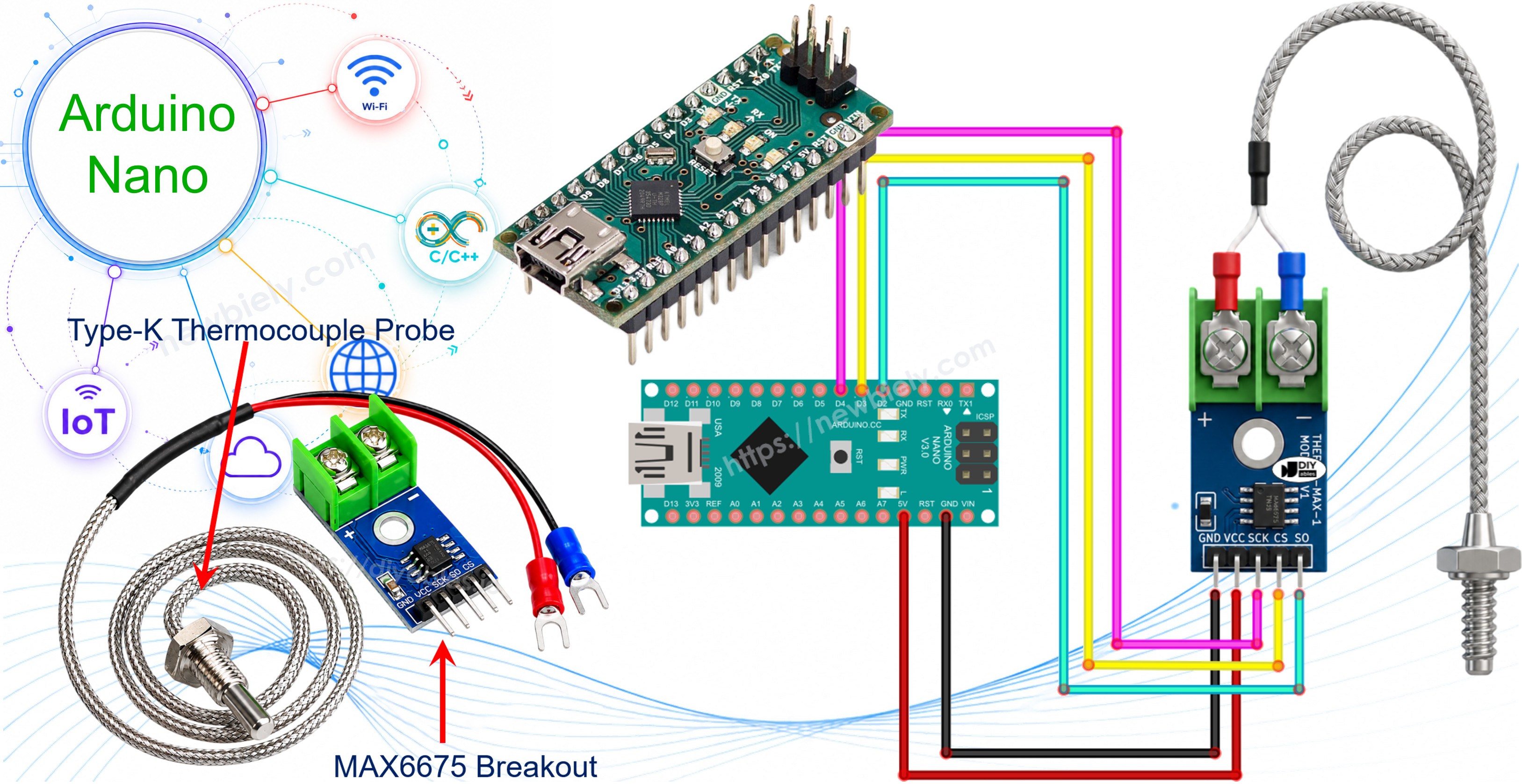
Most of the temperature sensors we cover in other tutorials - the DHTxx family, DS18B20, LM35 - top out somewhere around 125°C. That is fine for a room, a fridge, or a garden bed, but it is useless if you need to know what is happening inside a kiln, a smoker, or the exhaust of a small engine. For that kind of heat you need a completely different sensing element: a thermocouple. This tutorial walks through wiring a MAX6675 thermocouple module to an Arduino Nano and reading the temperature it reports, in both Celsius and Fahrenheit.
Hardware Preparation
Or you can buy the following kits:
| 1 | × | DIYables Sensor Kit (18 sensors/displays) |
Additionally, some of these links are for products from our own brand, DIYables .
What Is a Thermocouple?
A thermocouple is simply two wires made of different metals, welded together at one end. That joint is called the hot junction, and once it is heated, it generates a small voltage of its own - an effect known as the Seebeck effect. The hotter the junction gets, the more that voltage shifts, so measuring the voltage tells you the temperature. Because there are no delicate silicon components anywhere near the tip, the junction can be pushed to temperatures that would instantly destroy a normal electronic sensor.
Manufacturers combine different metal pairs to create different thermocouple "types," and the Type-K variant (Chromel paired with Alumel) is by far the one you will run into most often. It is inexpensive, rugged, and rated for roughly -328°F to +2300°F, which covers almost anything a hobbyist project will need.
The catch is that the voltage a thermocouple produces is measured in microvolts - far too small and far too noisy for an Arduino Nano's analog input to read directly. That's the job the MAX6675 chip was designed for.
Overview of the MAX6675 Thermocouple Module
What you'll actually hold in your hand is a small breakout board with the MAX6675 chip on it, plus a Type-K probe wired into a screw terminal on the board.
MAX6675 Module Pinout
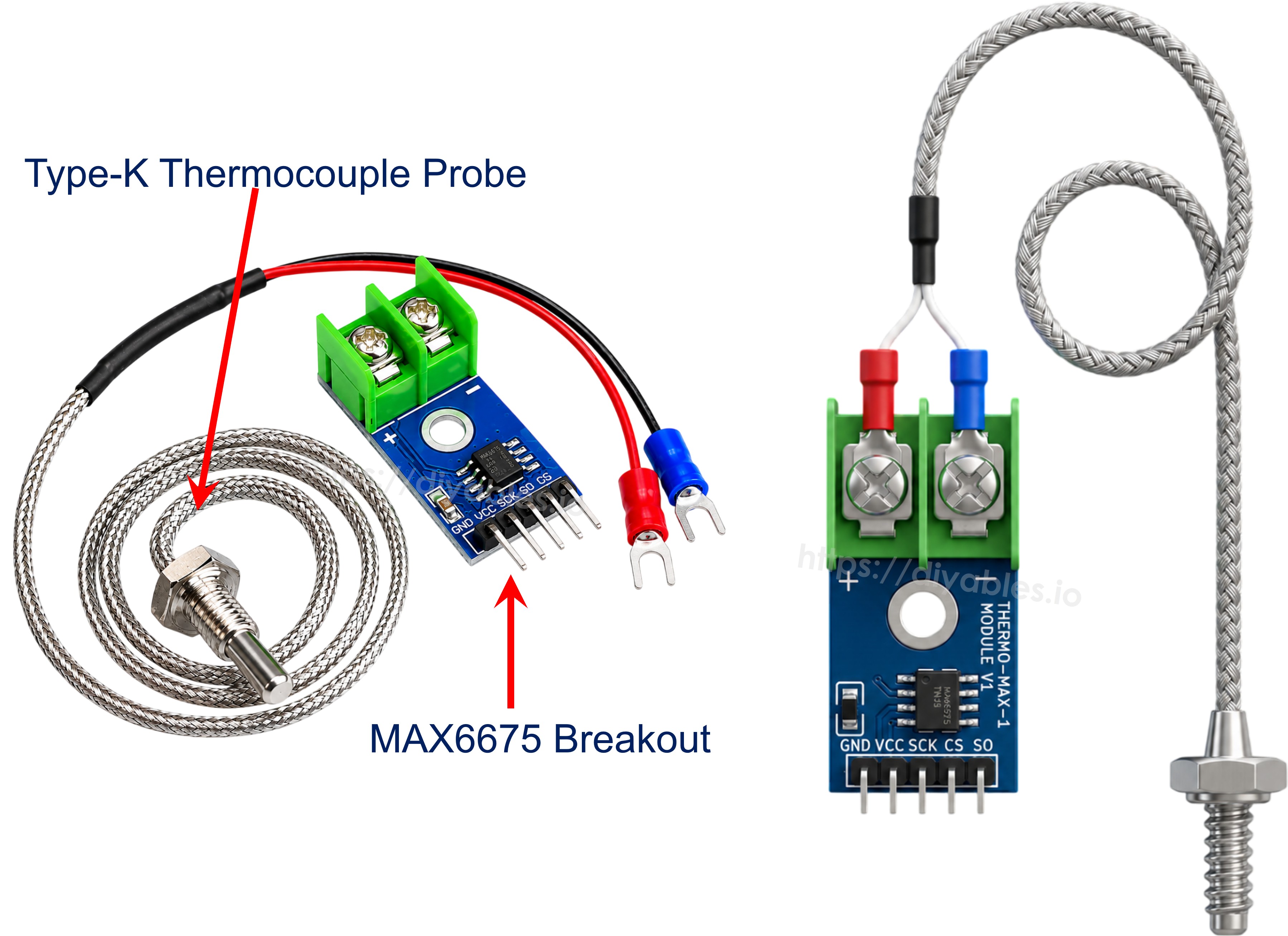
The MAX6675 chip amplifies the thermocouple's tiny signal, cancels out cold-junction error internally, and outputs a ready-to-use 12-bit temperature value. The Arduino Nano reads that value over a simple 3-wire serial interface - there's no data going back to the module, only out of it. The board exposes five pins:
- VCC: power input, accepts 3.0V to 5.5V.
- GND: ground reference.
- SCK: serial clock, driven by the Arduino Nano.
- CS: chip select; pulled low by the Arduino Nano while a reading is being taken.
- SO: serial data output (this is the module's only data line - it only ever sends, never receives).
On the opposite edge of the board sits a 2-pin screw terminal for the probe: the red lead goes to + and the blue lead goes to -. The probe itself is about 18 inches of shielded cable ending in a thin metal tip, and although the MAX6675 chip can digitize anything from 0°C up to 1024°C, the bundled probe is only rated for 0-80°C - keep that limit in mind if you plan on measuring anything hotter, since you'd need a higher-temperature probe to match.
Rounding out the specs: the module runs on 3.0-5.5V, resolves temperature in steps of about 0.25°C, and is accurate to within roughly ±3°C.
Wiring Diagram
Power the module first: VCC to the Arduino Nano's 5V pin and GND to any GND pin. Then pick any three free digital pins for SCK, CS, and SO - they don't need to support PWM or any special function, since the library talks to the chip in software. Finally, connect the thermocouple probe's red wire to the module's + terminal and the blue wire to -.
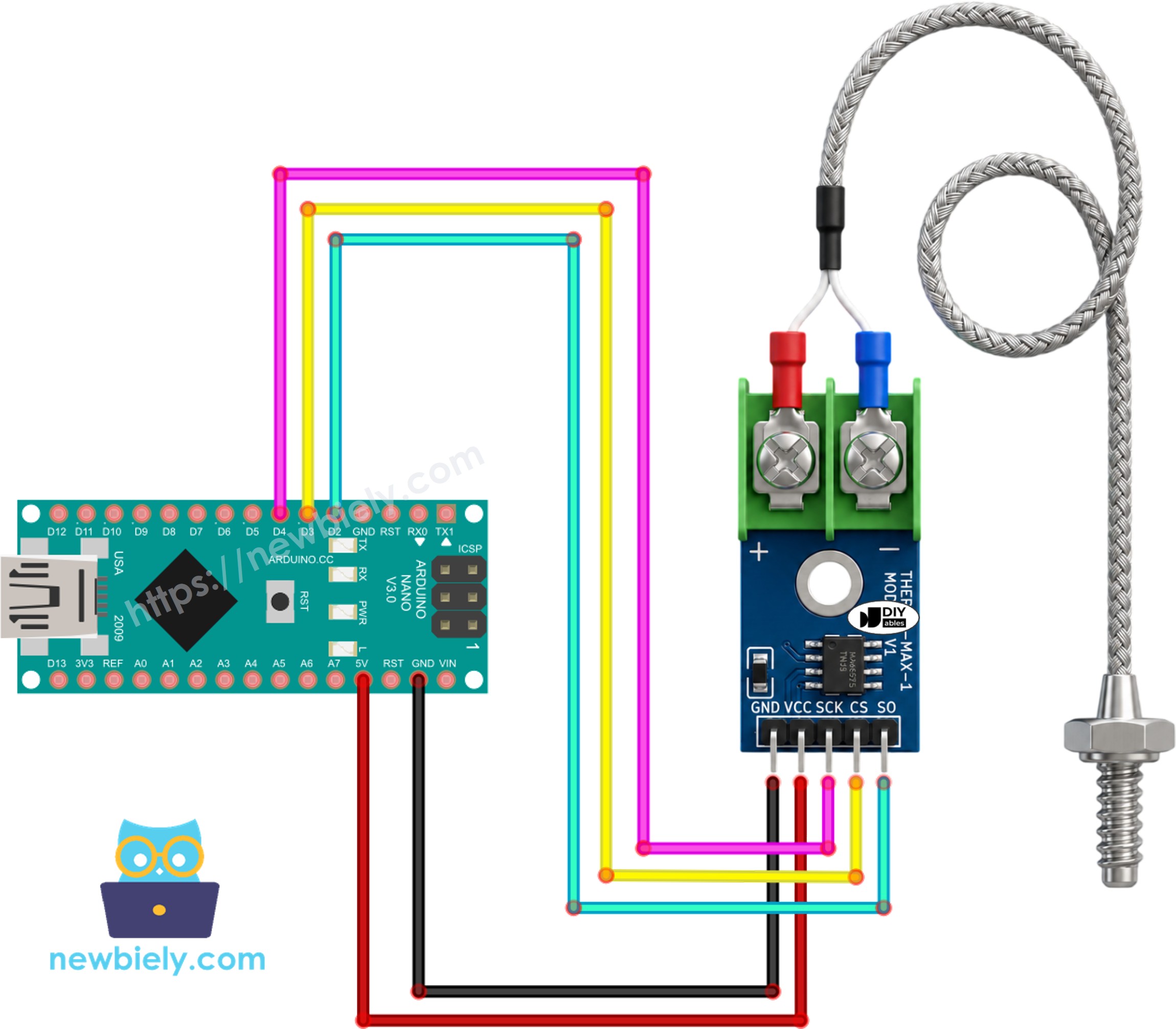
This image is created using Fritzing. Click to enlarge image
See The best way to supply power to the Arduino Nano and other components.
Wiring table of MAX6675 Module and Arduino Nano
| MAX6675 Module | Arduino Nano |
|---|---|
| VCC | → 5V |
| GND | → GND |
| SCK | → 4 |
| CS | → 3 |
| SO | → 2 |
Arduino Nano Code
Detailed Instructions
- Wire the MAX6675 module to the Arduino Nano exactly as shown in the diagram above.
- Plug the Arduino Nano into the PC with the USB cable.
- Open the Arduino IDE and pick the correct board and COM port.
- Click the Libraries icon on the left-hand sidebar.
- Type "MAX6675" into the search box and look for the library published by Adafruit.
- Hit Install to add it to your IDE.
- Search for MAX6675 library created by Adafruit and click the Install button.
- Paste the sketch above into the IDE.
- Press Upload to flash the Arduino Nano.
- Touch the probe tip to something warm - a cup of hot water works well for a first test.
- Open the Serial Monitor and watch the readings come in.
※ NOTE THAT:
If the Serial Monitor keeps printing the same value no matter what you do, recheck the SCK/CS/SO wiring first - a swapped pin is by far the most common mistake with this module.
Code Explanation
First, pull in the MAX6675 library header:
Next, three pin numbers are declared for the wires running to the module's SCK, CS, and SO pins:
Those three pins are then handed to the constructor of the MAX6675 class to build a thermocouple object:
Inside setup(), only the Serial Monitor connection needs to be opened, plus a short pause to give the MAX6675 chip time to complete its first internal conversion:
Inside loop(), the sketch asks the thermocouple object for a reading twice - once in Celsius, once in Fahrenheit - and prints both to the Serial Monitor:
A one-second delay closes out the loop, which keeps the reading pace easy to follow on the Serial Monitor without hammering the MAX6675 chip with back-to-back requests.