
Arduino Nano ESP32 - IR Slotted Optical Speed Sensor
In this guide, we will learn how to use the IR slotted optical speed sensor with Arduino Nano ESP32. In detail, we will learn:
- Why the slot sensor gives a LOW signal when an object sits in its gap.
- How to wire the sensor to the 3.3V pin and pin D2 of Arduino Nano ESP32.
- How to write a program for Arduino Nano ESP32 that counts every object moving through the gap.
- How to write a program for Arduino Nano ESP32 that reads the turning speed of a disc in RPM, using an interrupt function kept in fast memory.
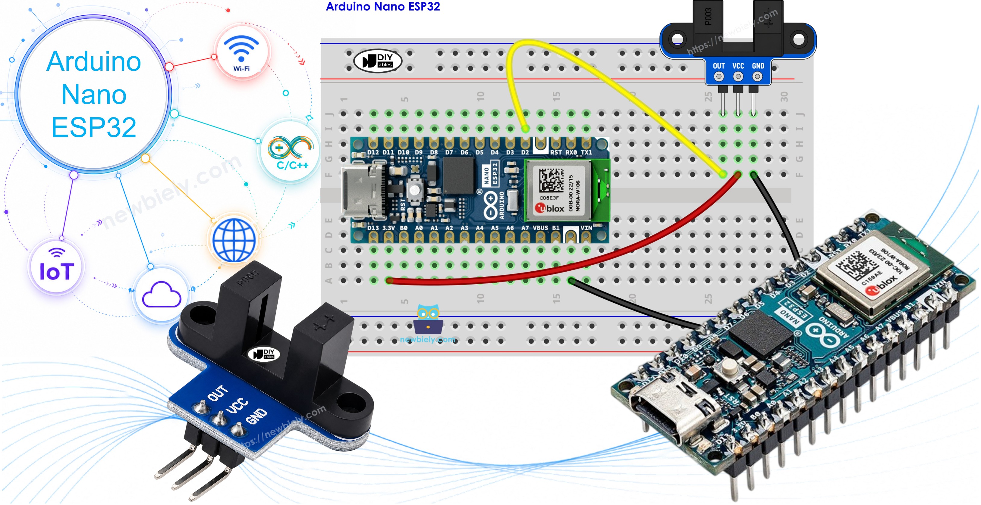
Hardware Preparation
Or you can buy the following kits:
| 1 | × | DIYables Sensor Kit (18 sensors/displays) |
Additionally, some of these links are for products from our own brand, DIYables .
Overview of IR Slotted Optical Speed Sensor
Look at the sensor from the side and you see the letter U. Inside the left and right walls of that U, two tiny parts look at each other: an infrared LED on one wall and an NPN phototransistor on the other. The open space between them is 5.9 mm wide. Some sellers name this part an opto interrupter, a photo interrupter, or simply an IR slot sensor. It is the same thing.
How It Works

Think of it as a tiny light gate. The LED never turns off, and the phototransistor keeps watching for its light.
- Nothing in the gap → the phototransistor gets the light → OUT reads HIGH.
- A solid object in the gap (a strip of paper card, a fingertip, one tooth of an encoder disc) → the light is cut → OUT reads LOW.
A Schmitt trigger sits on the module. It turns the light level into a sharp 0 or 1, with no bouncing between them. Because of this, your sketch does not need any debounce code.
Keep in mind:
- Glass and clear plastic can let infrared light pass, so the sensor may not see them. Pick something that light cannot go through.
- A few modules made by other brands use reversed logic: LOW when the gap is empty. If the first sketch below reports "blocked" with nothing in the gap, swap LOW and HIGH in that sketch. The speed sketch is fine with both types, since it counts one edge per tooth.
Specifications
| IR Slotted Optical Speed Sensor | |
|---|---|
| Sensor type | slot-type photoelectric (IR LED + NPN phototransistor) |
| Slot width | 5.9 mm |
| Operating voltage | 3.3V to 5V DC |
| Output | digital (TTL), LOW when blocked, HIGH when clear |
| Signal conditioning | built-in Schmitt trigger |
| Mounting | M3 screw holes at both ends |
| Pins | 3 (VCC, GND, OUT) |
Where people use it:
- A tachometer: put an encoder disc on a motor and read its RPM.
- Feedback on how fast a robot wheel spins.
- Counting parts, pulses, or things on a belt.
- Finding distance by counting how many times a wheel turns.
- An end-stop or home-position switch with no moving contacts.
Pinout
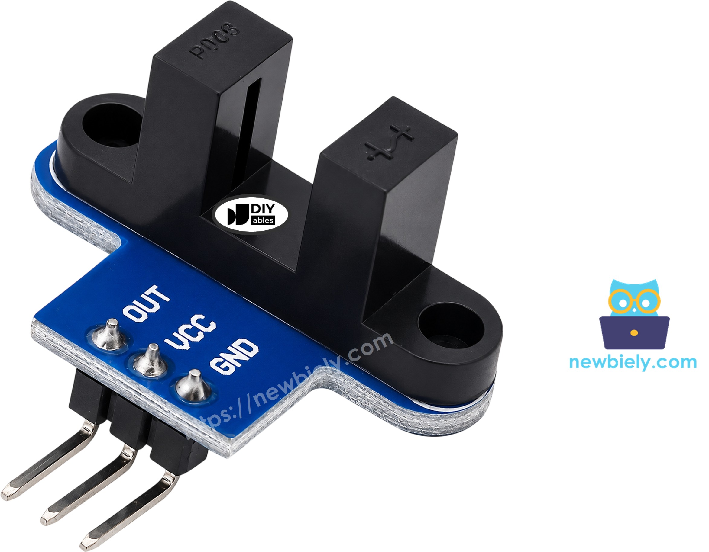
- OUT pin: the digital signal. Connect to a digital input of Arduino Nano ESP32 (D2 in this guide).
- GND pin: connect to GND (0V).
- VCC pin: connect to the 3.3V pin of Arduino Nano ESP32. The module works anywhere from 3.3V to 5V.
Batches are not all the same, and the three pins may come in a different order. Trust the labels on your own board, not the order in a picture.
Wiring Diagram
The Nano ESP32 runs on 3.3V logic, and its input pins are not made for 5V. The OUT signal rises as high as the voltage on VCC, so we feed the sensor from the 3.3V pin and not from 5V. This way, D2 never sees more than 3.3V.
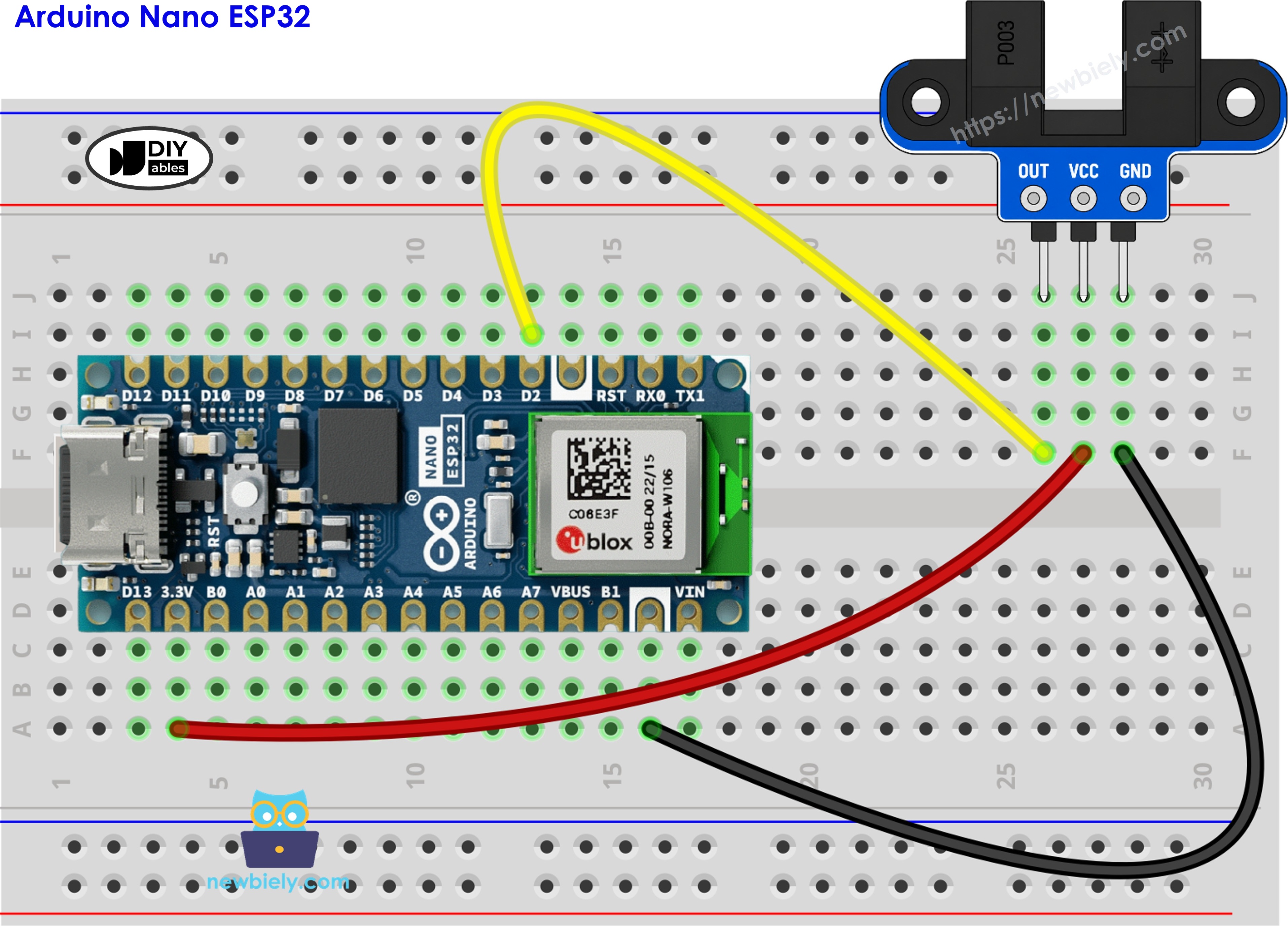
This image is created using Fritzing. Click to enlarge image
D2 also accepts an interrupt, which the speed sketch uses later.
How To Program For IR Slotted Optical Speed Sensor
There are two ways to read this sensor. Which one fits depends on how fast things move through the gap.
Way 1 - read the pin in loop() (good for slow objects):
- Tell the board that D2 is an input.
- Take a reading. A LOW value means the gap is blocked.
- Do something only when the new reading is not the same as the old one, then save it for next time.
Way 2 - let an interrupt count (needed for a spinning disc):
- Create the counter with the word volatile, since the interrupt function changes it in the background.
- Write the interrupt function. On the ESP32 chip, add IRAM_ATTR before its name. This puts the function in the chip's fast internal RAM, so it can run at once, every time.
- Link the function to D2. FALLING means the function runs when OUT drops from HIGH to LOW, which happens once each time a tooth enters the gap.
- Each second, take the count, set it back to zero, and turn it into RPM.
How does the math work? Say the disc has 20 slots. Then 20 pulses mean one full turn. Multiply the pulses from one second by 60 and you have pulses per minute. Divide that by 20 and you have turns per minute, which is RPM.
Arduino Nano ESP32 Code - Count Objects Passing the Slot
The sketch below reads D2 over and over. A new line shows up on the Serial Monitor only when the gap changes from clear to blocked, or back. Each time it becomes blocked, the counter goes up by one.
Detailed Instructions
Follow these instructions step by step:
- New to the Nano ESP32? First go through how to set up Arduino Nano ESP32 in the Arduino IDE.
- Wire the components according to the provided diagram. Double-check that VCC goes to 3.3V.
- Plug the Arduino Nano ESP32 into your computer with the Type-C cable.
- Launch the Arduino IDE on your computer.
- Select the appropriate Arduino Nano ESP32 board (e.g., Arduino Nano ESP32) and COM port.
- Paste the code into a new sketch.
- Press the Upload button and wait for it to finish.
- Open the Serial Monitor and choose 9600 baud.
- Push a strip of card into the gap, hold it a moment, and take it out. Repeat two more times.
- Read the messages:
The card makes one "blocked" line going in and one "clear" line coming out. While you hold it still, the screen stays quiet.
Arduino Nano ESP32 Code - Read Motor Speed (RPM)
A fast disc can push many teeth through the gap between two passes of loop(), so polling would lose some of them. This sketch uses an interrupt instead. The function countPulse() is marked with IRAM_ATTR so the ESP32 keeps it in fast memory and can jump to it right away. Once per second, the sketch prints how many pulses it got and the speed in RPM.
Look for SLOTS_PER_TURN near the top. It holds 20, the slot count of the encoder disc that usually ships with TT gear motors. Count the slots on your own disc and put that number here if it is not 20.
Mount the Encoder Disc
- Push the disc onto the motor shaft (or attach it to the wheel).
- Line up the sensor so the edge of the disc, with its teeth, runs inside the gap.
- Turn the disc slowly by hand to make sure it never rubs the walls of the U.
- To spin it, use your hand or run the motor. The motor has its own wiring, covered in the Arduino Nano ESP32 - DC Motor tutorial.
Detailed Instructions
- Do not change the sensor wiring.
- Paste the RPM code into the Arduino IDE.
- Press Upload.
- Open the Serial Monitor at 9600 baud.
- Get the disc turning, and then let it come to a stop.
- Watch the numbers. In this run the motor turns at around 300 RPM:
Try the math on the 101 line: 101 × 60 ÷ 20 = 303 RPM. The first and last lines show 0 because the disc is not moving.
For a robot wheel, you can also find how far it rolled: number of turns × π × wheel diameter.
※ NOTE THAT:
- Put very little code inside countPulse(). Never print from it.
- Every variable that the interrupt function changes needs the volatile keyword.
- Keep IRAM_ATTR in front of the interrupt function, so it stays in fast memory.
- To spot an object in front of the sensor (not inside a gap), see the obstacle sensor tutorial. For a knob that reports direction too, see the rotary encoder tutorial.