
Arduino Nano ESP32 - ACS712 Current Sensor
How much current does your motor really pull? Is your 12V LED strip drawing what its label says? In this guide, we will learn how to use the ACS712 current sensor with the Arduino Nano ESP32 to find out. The sensor runs on 5V, but the Nano ESP32 analog pins accept only 3.3V, so we will also add a small two-resistor divider. In detail, we will learn:
- How the ACS712 30A module turns a current into a voltage, and what its pins do.
- How to connect the ACS712 module to the Arduino Nano ESP32 safely, with a 10kΩ/20kΩ voltage divider.
- How to write a program for the Arduino Nano ESP32 that finds the zero point by itself and prints the DC current in amps.
- How to change the program to measure AC current (RMS).
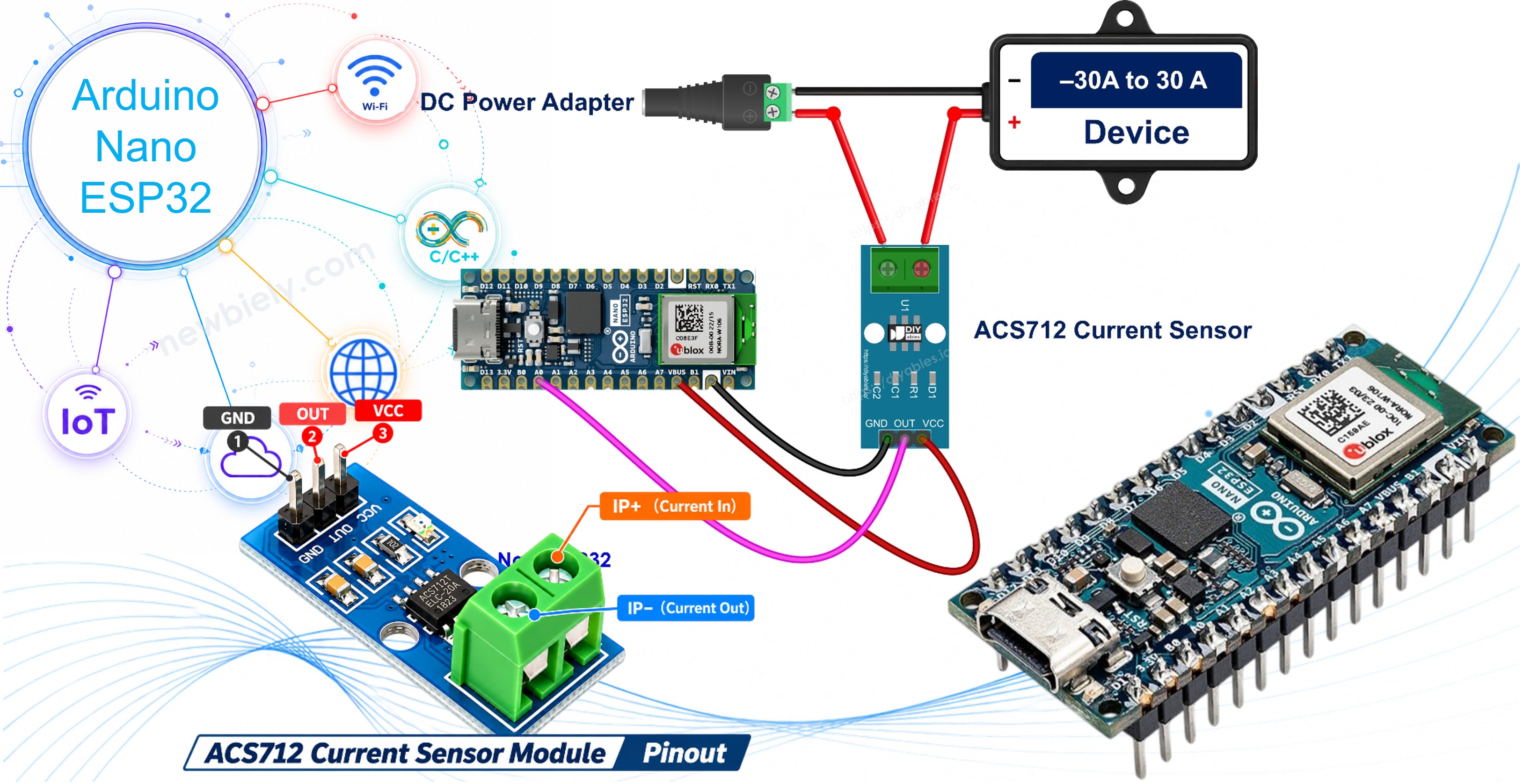
Hardware Preparation
Or you can buy the following kits:
| 1 | × | DIYables Sensor Kit (18 sensors/displays) |
Additionally, some of these links are for products from our own brand, DIYables .
Overview of ACS712 Current Sensor
The ACS712 is a small chip from Allegro that measures current, both DC and AC. Inside it, the current runs through a thick copper path. This current makes a magnetic field, and a Hall sensor right next to the path turns that field into a voltage. The copper path is not wired to the Nano ESP32 side at all (it is isolated up to 2.1 kV RMS), and its resistance is only about 1.2 mΩ, so it barely changes the circuit you measure.
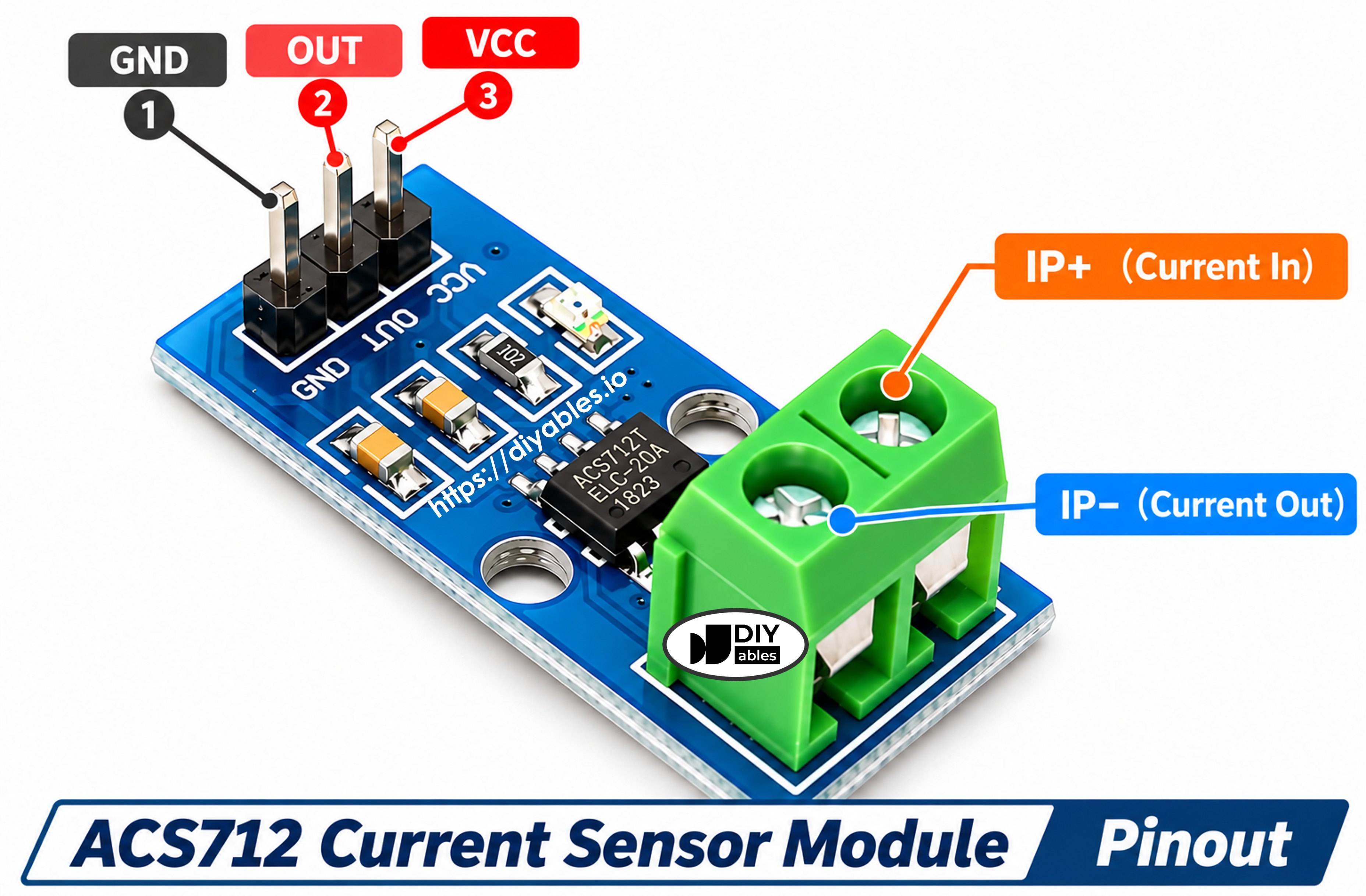
The module has a 3-pin header on one side and a 2-pin screw terminal on the other side:
- VCC pin: connect to 5V. On the Arduino Nano ESP32, use the VBUS pin (5V from USB). The 3.3V pin is not enough for this chip.
- GND pin: connect to GND (0V).
- OUT pin: analog output voltage. Connect it to the Arduino Nano ESP32 analog pin A0 through the voltage divider (see the wiring part).
- Screw terminal (IP+ and IP−, sometimes not labeled): this goes in series with the load. Cut one power wire of the load and put the terminal in the gap, so all of the load current flows through the sensor. Current that goes in at IP+ and out at IP− gives a positive reading.
A small LED on the board lights up when the module has power.
At 0 A, OUT sits at half of the supply, about 2.5V. When current flows one way, OUT goes up. When it flows the other way, OUT goes down. The output follows the real 5V supply (it is ratiometric), so if VBUS is 4.9V, the zero point is about 2.45V.
The chip comes in three current ranges. This guide uses the 30A version.
| ACS712 5A | ACS712 20A | ACS712 30A | |
|---|---|---|---|
| Current range | ±5A | ±20A | ±30A |
| Sensitivity | 185 mV/A | 100 mV/A | 66 mV/A |
| ACS712 30A Module | |
|---|---|
| Supply voltage | 5V (4.5V to 5.5V) |
| Output at 0 A | about 2.5V (half of VCC) |
| Output at +30 A | about 4.48V |
| Output at −30 A | about 0.52V |
| Sensitivity | 66 mV per amp |
| Bandwidth | 80 kHz |
| Total output error | about ±1.5% at 25°C |
| Isolation | 2.1 kV RMS |
| Copper path resistance | about 1.2 mΩ |
The 30A range is big, so the sensor is not good at small currents. The Nano ESP32 reads its analog pin with 12 bits, and after the divider one step is about 18 mA. With normal noise, you will see readings jump by about ±50 to 100 mA even with no load. So use it for loads of about 0.5 A and up: motors, lamps, LED strips, heaters and chargers. The code averages many readings to make the numbers calmer.
How the Sensor Output Becomes Amps
Each amp moves the output by 66 mV, starting from the zero voltage. So the formula is:
Example: if Vzero is 2.49V and Vout reads 2.56V, the current is (2.56 − 2.49) / 0.066 ≈ 1.06 A.
Do not trust the 2.5V number blindly. Every module and every USB port is a bit different. The code measures Vzero at startup, while no current flows, and uses that value.
Wiring Diagram
The ACS712 needs 5V, so its VCC goes to VBUS. But then OUT can rise to about 4.5V, which is too high for a 3.3V analog pin. Two resistors fix this: OUT → 10kΩ → A0 → 20kΩ → GND. Pin A0 now sees 2/3 of the sensor voltage (4.5V becomes 3.0V), and the code multiplies the reading by 1.5 to get the real value back.
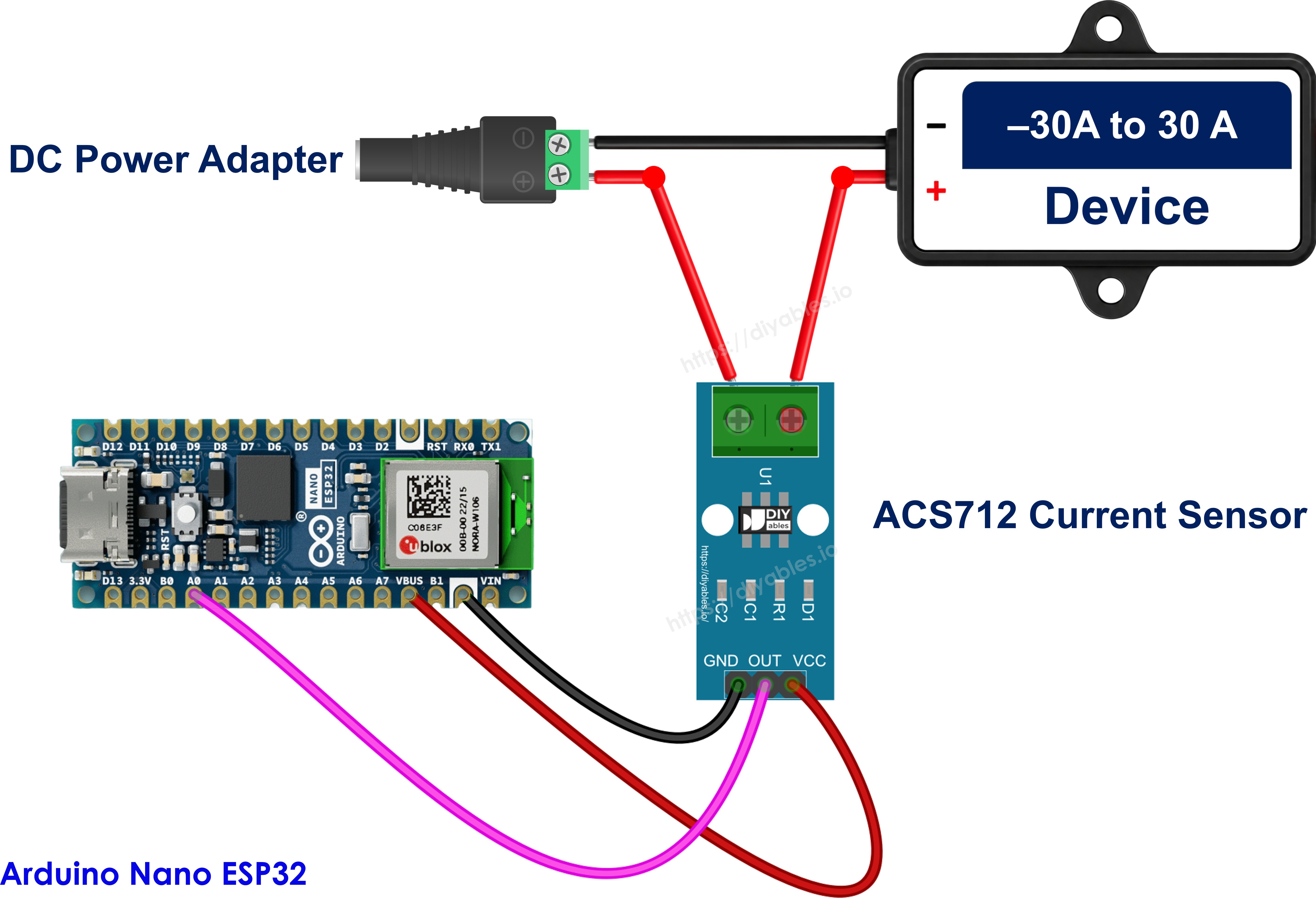
This image is created using Fritzing. Click to enlarge image
Wiring table of ACS712 Module and Arduino Nano ESP32
| ACS712 Module | Arduino Nano ESP32 |
|---|---|
| VCC | → VBUS (5V) |
| GND | → GND |
| OUT | → 10kΩ resistor → A0 (and A0 → 20kΩ resistor → GND) |
On the load side, the 12V adapter plugs into the DC power jack. Run the jack's + wire to one screw of the ACS712, the other screw to the + of the 12V DC device (for example a DC motor, LED strip or lamp), and the DC device − back to the jack's − wire. The 12V circuit and the Nano ESP32 share no wires.
We use A0 because it belongs to ADC1 of the ESP32-S3 chip. The A4 to A7 pins belong to ADC2, which stops working while WiFi is on. With A0, you can add WiFi to this project later.
※ NOTE THAT:
Mains AC (110V/220V) is dangerous. Learn with a low-voltage DC load first, like the 12V DC device in this guide. If you ever measure a mains circuit, never touch the screw terminal or its wires while the power is on. That side of the module carries the full load voltage.
How To Program For ACS712 Current Sensor
No library is needed.
- Set the analog pin and the numbers for the divider and the sensor:
- Let the analog pin read up to about 3.1V:
- Read the pin voltage in millivolts and turn it back into the real sensor voltage. analogReadMilliVolts() uses the chip's own calibration, so it is more accurate than analogRead():
- Find the zero point in setup(), while the load is OFF, by averaging 1000 readings.
- Turn the voltage into amps:
Arduino Nano ESP32 Code - ACS712 DC Current
The code below finds the zero voltage at startup. Then, every 0.5 seconds, it averages 300 readings and prints the sensor voltage and the current.
Detailed Instructions
Follow these instructions step by step:
- If this is the first time you use Arduino Nano ESP32, see how to setup environment for Arduino Nano ESP32 on Arduino IDE.
- Wire the components according to the provided diagram. Leave the 12V adapter unplugged for now.
- Connect the Arduino Nano ESP32 to your computer using a USB Type-C cable.
- Launch the Arduino IDE on your computer.
- Select the appropriate Arduino Nano ESP32 board (e.g., Arduino Nano ESP32) and COM port.
- Copy the code above and paste it into the Arduino IDE.
- Open the Serial Monitor and set the baud rate to 9600.
- Click the Upload button to send the code to the Arduino Nano ESP32. The load must be OFF while the board starts, because this is when the zero point is measured.
- Wait until the Serial Monitor shows the zero voltage. Then plug in the 12V adapter to turn the DC device on.
- Watch the current go up. If your DC device is a motor, hold its shaft lightly with your fingers and the current rises more.
The first lines show a few tens of mA with no load. That is normal noise for the 30A version. If the numbers come out negative when the DC device is on, swap the two wires on the screw terminal.
※ NOTE THAT:
If the reading is far off, check that VCC is on VBUS and not on 3.3V, and that the 10kΩ resistor sits between OUT and A0 while the 20kΩ resistor sits between A0 and GND. If the two resistors are swapped, the pin only sees 1/3 of the voltage.
Measuring AC Current
With AC, the current changes direction many times per second (50 or 60 times, depending on your country). The sensor output swings above and below the zero voltage, so a plain average gives almost 0 A. We use the RMS value instead. The code samples the signal for 200 ms, which covers 10 cycles at 50 Hz and 12 cycles at 60 Hz. For each sample it takes the distance from the zero voltage and squares it. Then:
Safety again: a mains circuit can kill. Do not try this on 110V/220V unless you know how to work with mains safely, and keep your hands away from the screw terminal while the power is on. The wiring to the Nano ESP32 and the zero calibration are the same as above.
Arduino Nano ESP32 Code - ACS712 AC Current
Upload it the same way, with the load off at startup. Example output with a small AC appliance switched on after the calibration:
Noise also adds a small RMS value when nothing is on, so a reading below about 0.1 A means "about zero".