
Arduino Nano ESP32 - MOSFET Module
In this guide, we will learn how to use a MOSFET module with the Arduino Nano ESP32 to drive a 12V load. The Nano ESP32 pins give only 3.3V and a tiny current, so they cannot power a 12V LED strip or fan on their own. The MOSFET module sits in the middle and does the heavy work. In detail, we will learn:
- How to wire the AOD4184, LR7843 or FR120N MOSFET module, a 12V power adapter and a 12V LED strip to the Arduino Nano ESP32.
- How to write a program for the Arduino Nano ESP32 to turn the load fully ON and OFF, and to change its power step by step with PWM.
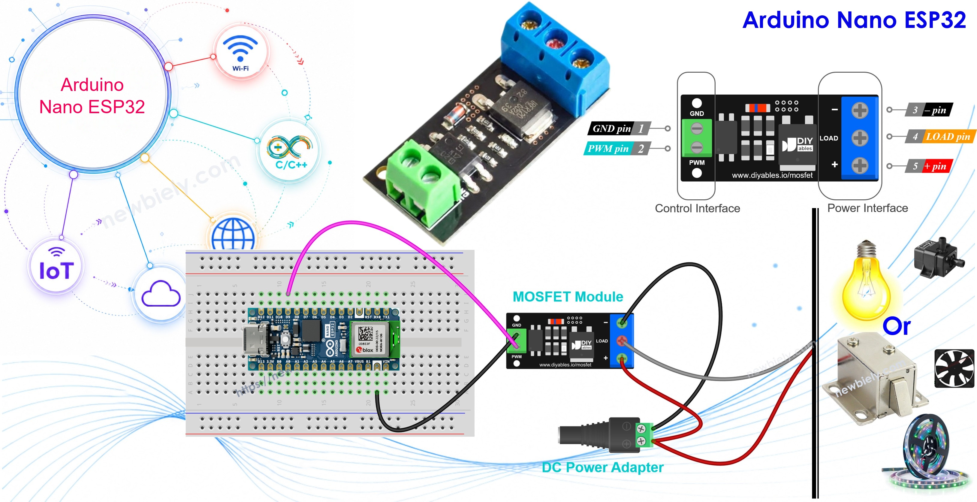
Once this works, you can later add WiFi to the same sketch and set the power of your strip or fan from a phone or a web page.
Or you can buy the following kits:
| 1 | × | DIYables Sensor Kit (18 sensors/displays) |
Additionally, some of these links are for products from our own brand, DIYables .
Overview of MOSFET Module
Think of the MOSFET module as an electronic switch with no moving parts. The Nano ESP32 sends a small 3.3V signal, and the module opens or closes the path of a much bigger DC current. It works with 12V LED strips, DC motors, fans, pumps, solenoid valves and heaters.
This one guide covers three modules: AOD4184 (also sold as D4184), LR7843 and FR120N. They use the same board design. The size, the pins, the wiring and the code are all the same. Only the MOSFET chip on the board is different.
Why pick a MOSFET module and not a relay? A relay clicks and wears out over time, and it can only do ON or OFF. The MOSFET module is silent, very fast and lasts a long time. It also accepts PWM, so you can dim an LED strip or slow down a fan. The one limit: it is for DC loads only. Never use it with AC mains.
| AOD4184 | LR7843 | FR120N | |
|---|---|---|---|
| MOSFET | AOD4184A (N-channel) | IRLR7843 (N-channel) | IRFR120N (N-channel) |
| Max load voltage (MOSFET rating) | 40V DC | 30V DC | 100V DC |
| Max current (MOSFET rating) | 50A | 161A | 9.4A |
| On-resistance RDS(on) | about 7 mΩ | about 3.3 mΩ | about 210 mΩ |
| Practical current without heatsink | about 10–15A | about 15A | about 2A |
| Control signal | 3.3V / 5V logic, active HIGH | 3.3V / 5V logic, active HIGH | 3.3V / 5V logic, active HIGH |
| Isolation | PC817 optocoupler | PC817 optocoupler | PC817 optocoupler |
| PWM | yes, keep ≤ ~1 kHz | yes, keep ≤ ~1 kHz | yes, keep ≤ ~1 kHz |
| Load type | DC only | DC only | DC only |
Which one should you buy?
- LR7843: the lowest resistance, so it stays the coolest at high current. A good pick for big 12V or 24V loads, like long LED strips or large motors. Max 30V.
- AOD4184: a good all-rounder. It handles up to 40V with strong current, so it fits 12V, 24V and 36V loads.
- FR120N: it takes the highest voltage (up to 100V), but its resistance is also the highest. Keep it to small currents, about 2A without a heatsink. Good for small 24V or 48V loads.
The 50A and 161A numbers are limits of the chip itself, not of the small board. In real use, heat is the limit. After a few minutes of running, touch the module. If it is too hot, lower the load or add a heatsink.
How It Works
The input side has a PC817 optocoupler, and the signal from pin D9 takes this path: PWM pin → small resistor → LED inside the PC817 → light → phototransistor inside the PC817 → MOSFET gate. A resistor on the gate pulls it to 0V when the PC817 is off. Only light crosses the PC817, so the Nano ESP32 side and the 12V side never touch each other. The signal GND and the load GND are not connected on the module.
The MOSFET is an N-channel low-side switch. It sits between the LOAD terminal and the − terminal, so it switches the negative wire of the load, not the positive one. The load itself is connected between + and LOAD.
Here is what the module does with each kind of signal from D9.
HIGH (3.3V) on the PWM pin → load at full power
- A few mA flow into the LED inside the PC817, and it turns on (you cannot see it, it is inside the chip).
- The phototransistor conducts and feeds the MOSFET gate about half of the load supply. With a 12V adapter, that is about 6V.
- The MOSFET is now fully ON, like a closed switch. Its resistance is tiny: a few mΩ (AOD4184, LR7843) or about 0.2Ω (FR120N).
- Current runs from adapter + to the + terminal, through the load, into LOAD, through the MOSFET, out of −, and back to adapter −.
- The load sees almost the full 12V. The 3.3V pin is enough for this, because the PC817 LED needs only a small current. No level shifter is needed.
- Code: analogWrite(MOSFET_PIN, 255), or 100% duty.
LOW (0V) on the PWM pin → load off
- No current, so the LED inside the PC817 stays dark.
- The phototransistor is off. The gate resistor holds the gate at 0V.
- The MOSFET is OFF, like an open switch between LOAD and −.
- The negative wire of the load is cut from the adapter, so no current flows and the load gets 0V.
- Code: analogWrite(MOSFET_PIN, 0), or 0% duty.
PWM signal on the PWM pin → load at part power
- D9 flips between LOW and HIGH very fast. The Nano ESP32 analogWrite() uses 1 kHz by default, which means 1000 times per second.
- The MOSFET follows each flip: ON for every HIGH part, OFF for every LOW part. The load gets 12V pulses.
- The duty cycle is how much of the time the pin is HIGH. It is the analogWrite() value divided by 255. The average voltage and power are the duty cycle times the full value. With a 12V supply:
- AnalogWrite 64 (25%) → about 3V average → about a quarter of the power
- AnalogWrite 128 (50%) → about 6V average → about half of the power
- AnalogWrite 191 (75%) → about 9V average → about three quarters of the power
- An LED strip looks dimmer, since it blinks too fast for your eyes. A fan, motor or pump turns slower, since its rotating part smooths the pulses. A fan may not start at a low duty cycle.
- The PC817 is slow, so keep the frequency at about 500 Hz to 1 kHz. The 1 kHz default is fine. At a much higher frequency, the MOSFET does not switch fully, the pulses get messy and the MOSFET gets hot.
- Do not use PWM on a solenoid lock or valve. Use only HIGH and LOW for them.
A few rules to remember:
- Since the gate only gets about half of the load supply, the load supply must be at least about 6V. A 5V load supply will not work well. If the load draws more than a few amps, use 9V or more.
- The board has no flyback diode. For a motor, pump, solenoid or relay coil, add an external diode (for example 1N5819 or 1N4007) across the load. Connect the cathode (the side with the stripe) to load + and the anode to load −.
Pinout
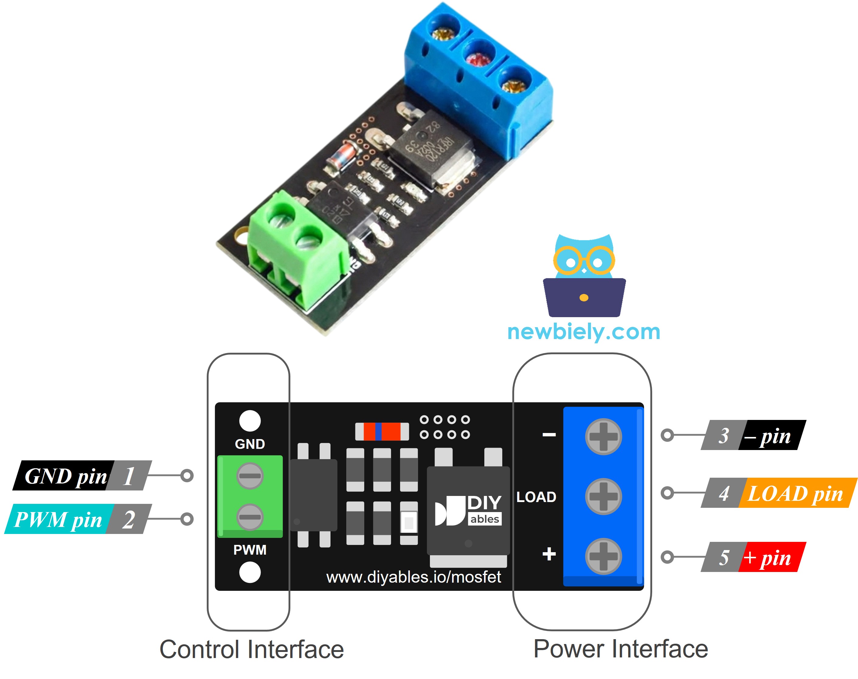
The module has two groups of pins. A 2-pin header (2.54mm, fits a breadboard) is on the control side, and screw terminals are on the power side.
Control side:
- PWM pin: connect to a GPIO pin of the Arduino Nano ESP32 (the control signal)
- GND pin: connect to GND of the Arduino Nano ESP32 (signal ground)
Power side:
- + pin: connect to the positive of the load power supply (for example 12V) AND to the positive wire of the load. Both wires share this one terminal.
- LOAD pin: connect to the negative wire of the load (this is the switched side, it goes to the MOSFET drain)
- − pin: connect to the negative (ground) of the load power supply
The labels can be a bit different between batches. Always read the text printed on your own board.
Wiring Diagram
The Nano ESP32 only sends a signal from pin D9 (plus GND) to the PWM and GND pins of the module, while the 12V adapter feeds the load through the screw terminals, so the 12V never goes near the board's pins.
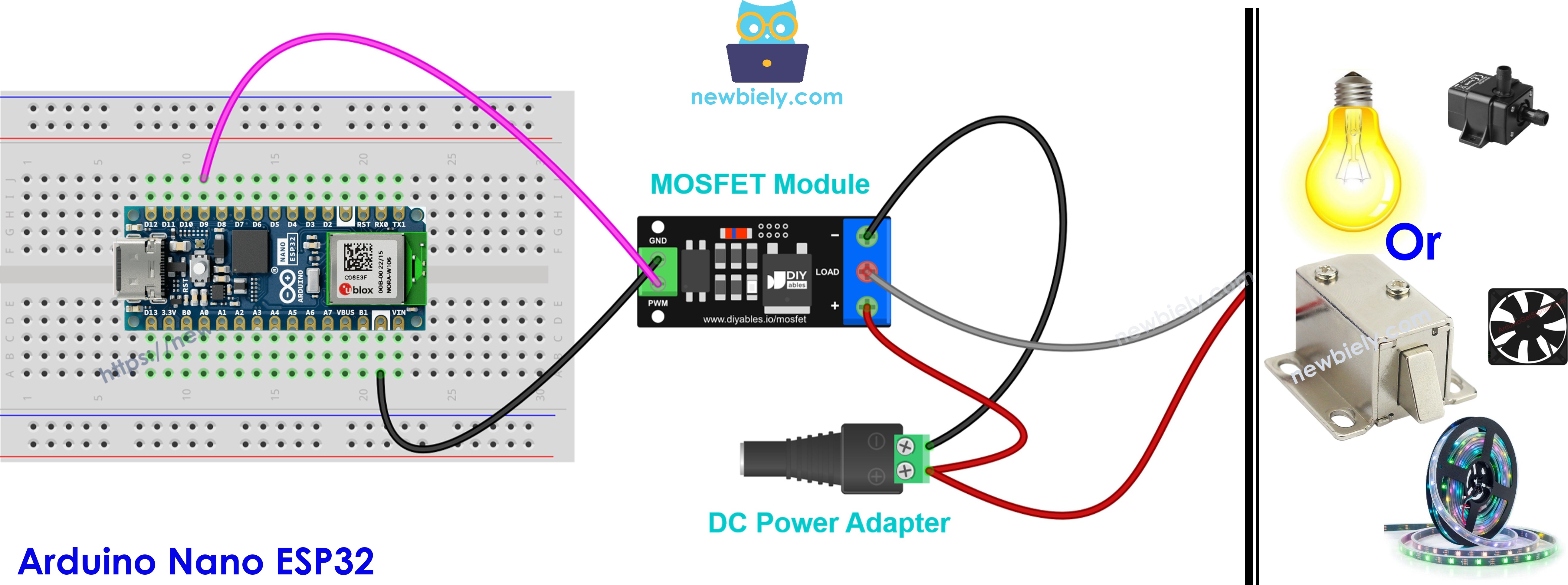
This image is created using Fritzing. Click to enlarge image
Examples: Wiring Different Loads
Want to drive something other than an LED strip? Keep the D9 and GND wires from the Nano ESP32 as they are. Only the power side changes, and the pattern is always the same:
- 12V adapter + to the + terminal, and adapter − to the − terminal.
- Load + wire to the same + terminal, and load − wire to the LOAD terminal.
Before you start:
- Match the adapter to the load. A 12V load needs a 12V adapter. The module needs at least 6V to work.
- Match the module to the current. The FR120N is OK for small loads only (about 2A without a heatsink). For bigger loads, use the AOD4184 or LR7843.
- You can upload the same code for every load. For a solenoid, just use full ON and full OFF (HIGH and LOW) in place of the fade.
The flyback diode from the "How It Works" part is needed for every load below that has a coil inside: the motor, the fan, the pump and both solenoids. Put it across the two load wires, stripe to +.
12V DC Motor Example
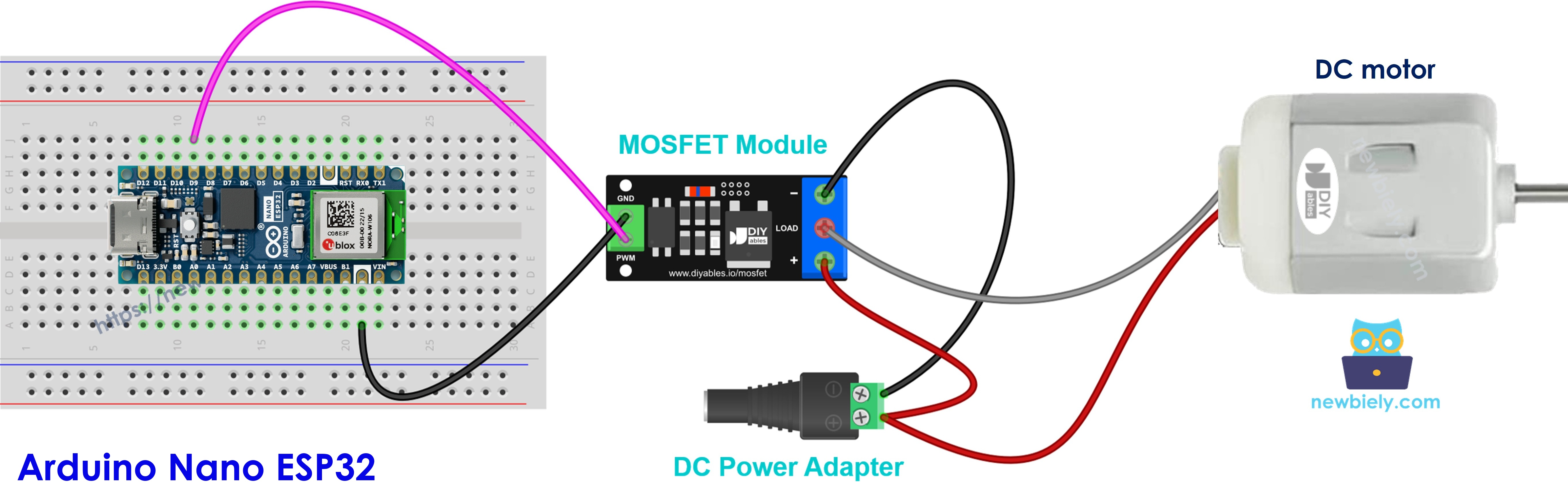
This image is created using Fritzing. Click to enlarge image
Motor + goes to +, motor − goes to LOAD. Add the diode (1N5819 or 1N4007): the stripe side (cathode) to motor +, the other side (anode) to motor −. PWM changes the speed.
The module can only spin the motor one way. If you need forward and reverse, use a motor driver like the L298N instead. The Arduino Nano ESP32 - DC Motor guide shows how.
12V Cooling Fan Example
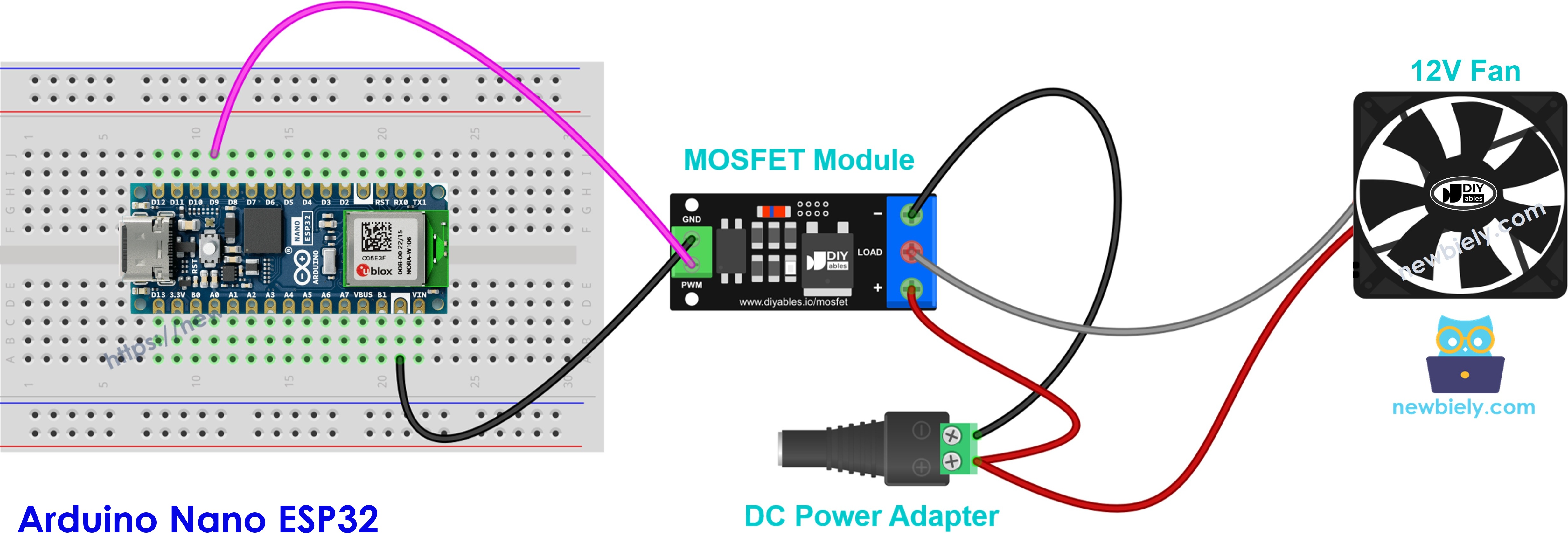
This image is created using Fritzing. Click to enlarge image
Red wire (+) goes to +, black wire (−) goes to LOAD. If your fan has a yellow wire, that is the speed signal. Leave it free. The diode is a good idea here as well, since it is cheap and safe. PWM sets the fan speed, but a fan may not start at a low duty cycle, so start from about 30% or more.
12V LED Strip Example
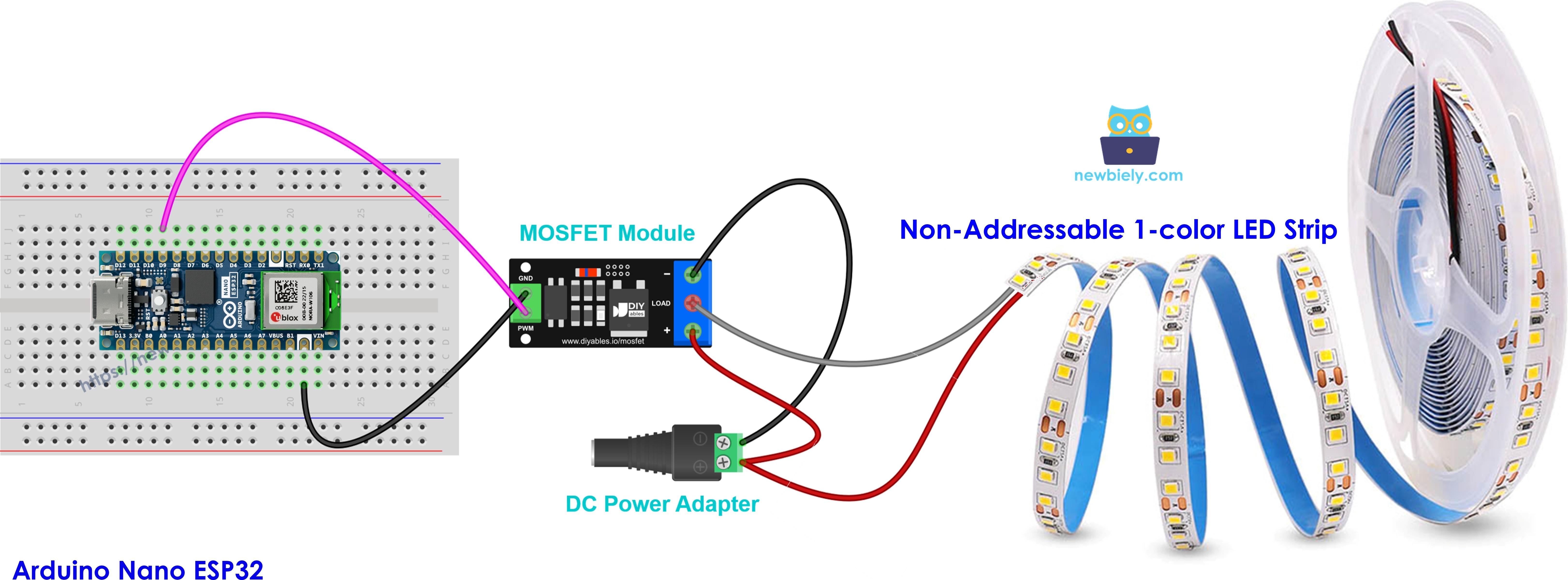
This image is created using Fritzing. Click to enlarge image
This is the same load as the main diagram. Strip + (often labeled 12V) to +, strip − to LOAD. No diode is needed, because an LED strip has no coil. PWM sets the brightness. A long strip draws more current, so check its current first and pick the module to fit. Note: this works for a single color strip, not for RGB or addressable strips.
12V Water Pump Example
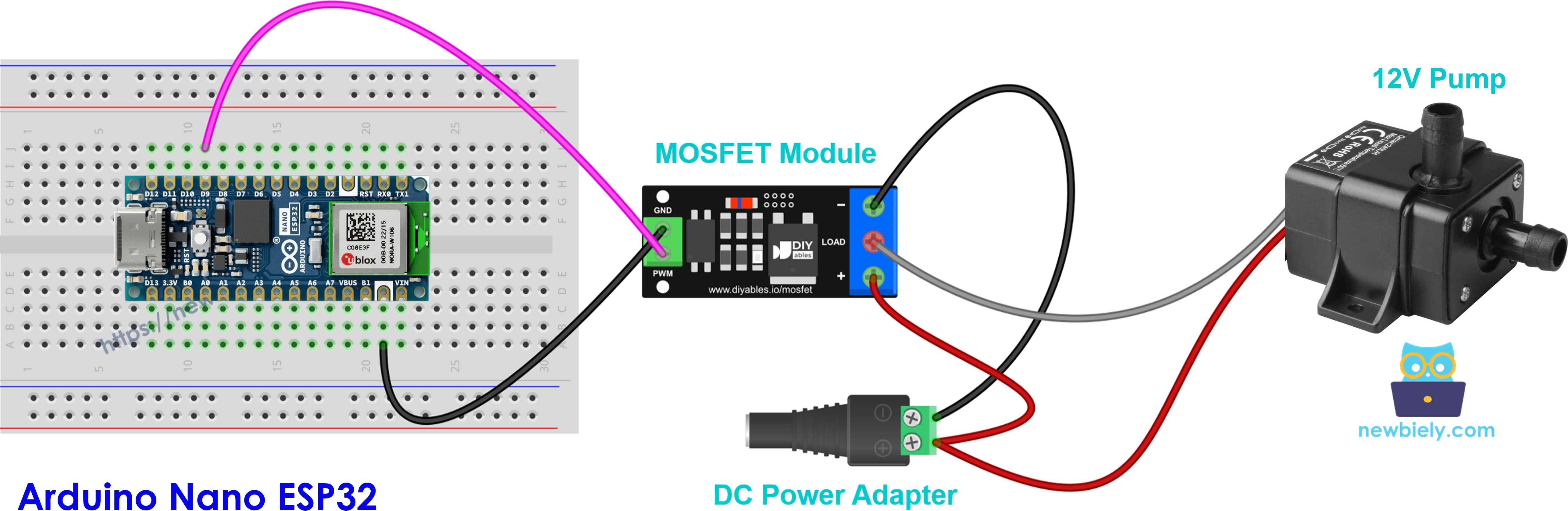
This image is created using Fritzing. Click to enlarge image
Pump + to +, pump − to LOAD, and add the diode. PWM sets the water flow. Do not let the pump run without water.
12V Solenoid Lock Example
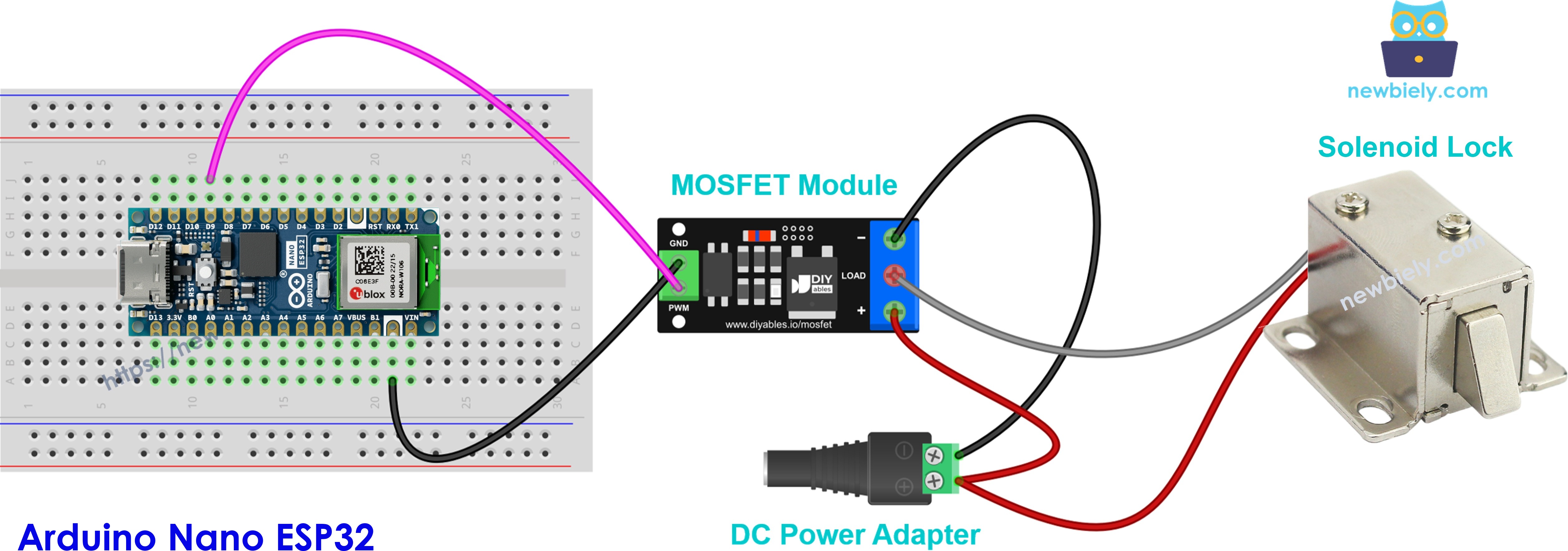
This image is created using Fritzing. Click to enlarge image
Wire it like the pump, with the diode. Only switch it fully ON or fully OFF (100% or 0%). No PWM dimming. The lock gets hot if you keep it ON, so turn it ON for a short moment to unlock, then OFF.
12V Solenoid Valve Example
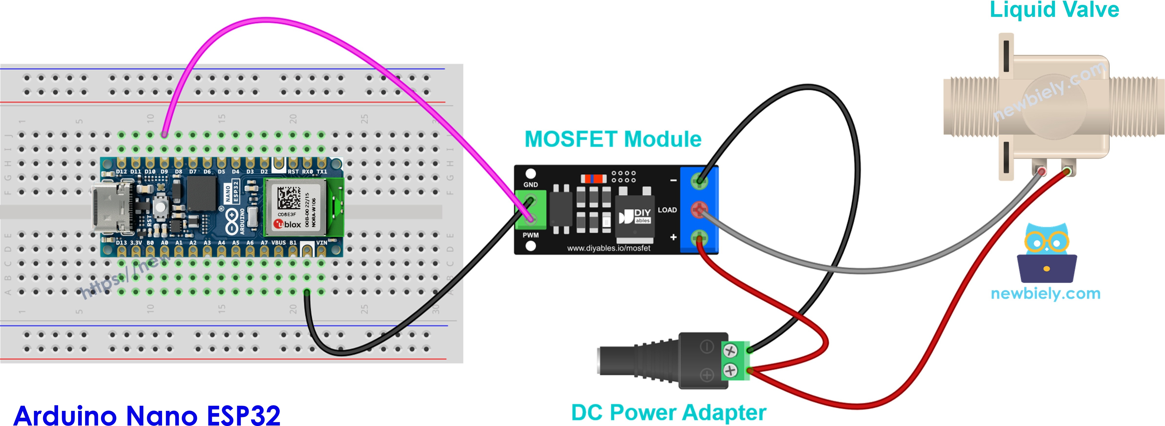
This image is created using Fritzing. Click to enlarge image
Same wiring, same diode. This is a normally closed valve: ON opens it, OFF closes it. Use ON and OFF only, not PWM.
How To Program For MOSFET Module
No library is needed. The Nano ESP32 uses the built-in analogWrite() function.
- Set the pin on the Arduino Nano ESP32 that connects to the PWM pin of the module:
- Make the pin an output and start with the load OFF:
- Turn the load fully ON:
- Turn the load OFF:
- Set the load to a power level in percent (0 to 100):
If you only need ON and OFF, digitalWrite(MOSFET_PIN, HIGH) and digitalWrite(MOSFET_PIN, LOW) also work.
Arduino Nano ESP32 Code - MOSFET Module
The code below turns the load ON for 2 seconds and OFF for 2 seconds. Then it raises the power from 10% to 100% in 10% steps, every 0.5 seconds. After that, it lowers the power from 90% back to 0%, waits 1 second, and starts again.
Detailed Instructions
Follow these instructions step by step:
- If this is the first time you use Arduino Nano ESP32, see how to setup environment for Arduino Nano ESP32 on Arduino IDE.
- Wire the components according to the provided diagram. Leave the 12V adapter unplugged for now.
- Connect the Arduino Nano ESP32 to your computer using a USB Type-C cable.
- Launch the Arduino IDE on your computer.
- Select the appropriate Arduino Nano ESP32 board (e.g., Arduino Nano ESP32) and COM port.
- Copy the code above and paste it into the Arduino IDE.
- Click the Upload button to send the code to the Arduino Nano ESP32.
- Plug in the 12V power adapter.
- Open the Serial Monitor and set the baud rate to 9600.
- Watch the LED strip: full brightness for 2 seconds, dark for 2 seconds, then it slowly gets brighter and slowly gets dimmer again.
If you connected a 12V fan, you will hear it spin at full speed, stop, and then speed up and slow down in the same pattern.