
Arduino Nano - PC817 Optocoupler: Monitor 12V/24V DC Input Signal
This tutorial instructs you how to use Arduino Nano with a PC817 optocoupler module to find out whether a 12V or a 24V device is switched on right now, with no electrical connection at all between that device and the board. In detail, we will learn:
- Which of the three PC817 optocoupler modules - 3-5V, 12V or 24V - has to be bought for the signal you want to watch
- How to wire a PC817 optocoupler module to Arduino Nano
- How to tell whether your module is active-LOW or active-HIGH, and how to flip the code with one edit
- How to tap the module in parallel with a lamp, a coil or a motor so the Arduino Nano follows its real on/off state
- How to program Arduino Nano to read the isolated digital input
- Why the ground of the 12V/24V circuit must stay separate from the Arduino Nano GND
- How to build the same thing from the bare 4-pin PC817 chip, if you prefer
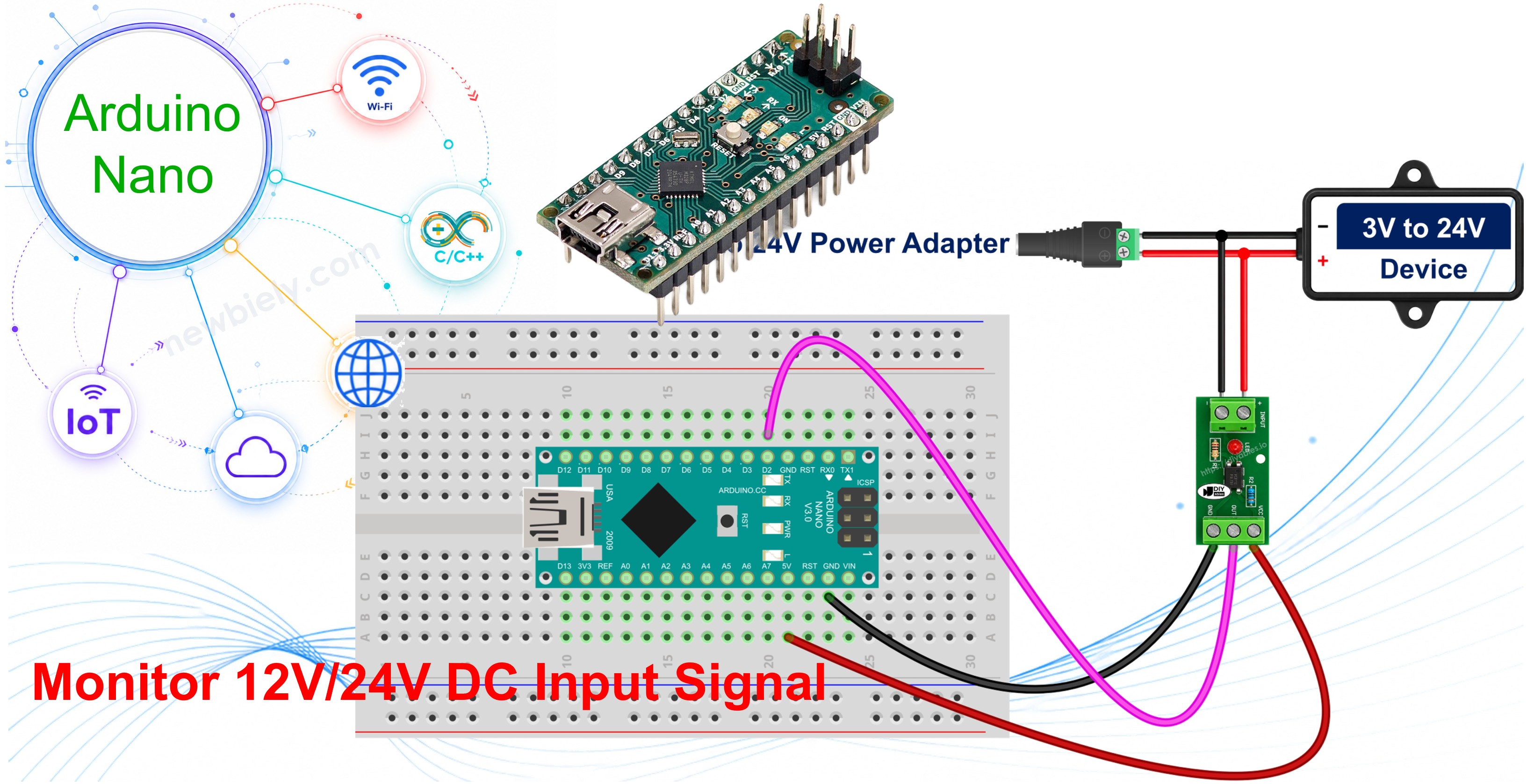
Because the Arduino Nano is small enough to hide inside a compact enclosure or behind a vehicle dashboard, it is often installed right next to circuits that run far above its own 5V. Two jobs come up again and again, and both of them are really the same question - is that device on or off at this moment?
- Checking whether a 12V vehicle circuit is live - the ignition line, the headlights, or a door switch - so a Nano-based logger or alarm knows when the car is in use.
- Watching a 24V solenoid, contactor or relay coil in a machine cabinet to confirm that it really was energized, and counting the hours it has spent that way.
In both cases the Arduino Nano must never touch that voltage. The PC817 sits in between and lets the information cross while the electricity stays behind. A vehicle install is the example used throughout this tutorial, so the 12V module is the one shown in the diagrams - the 24V and the 3-5V modules are wired in exactly the same way.
We suggest:
- Using a relay if you want to switch a 12V or 24V load rather than sense one. A PC817 only reads a signal, it cannot drive a load.
- Using a voltage sensor if you need the actual value of a DC voltage instead of a simple present/absent state.
Hardware Preparation
Or you can buy the following kits:
| 1 | × | DIYables Sensor Kit (18 sensors/displays) |
Additionally, some of these links are for products from our own brand, DIYables .
The module lines above are alternatives, not a shopping list - buy the single one that matches the voltage of the signal you intend to watch.
Overview of PC817 Optocoupler Module
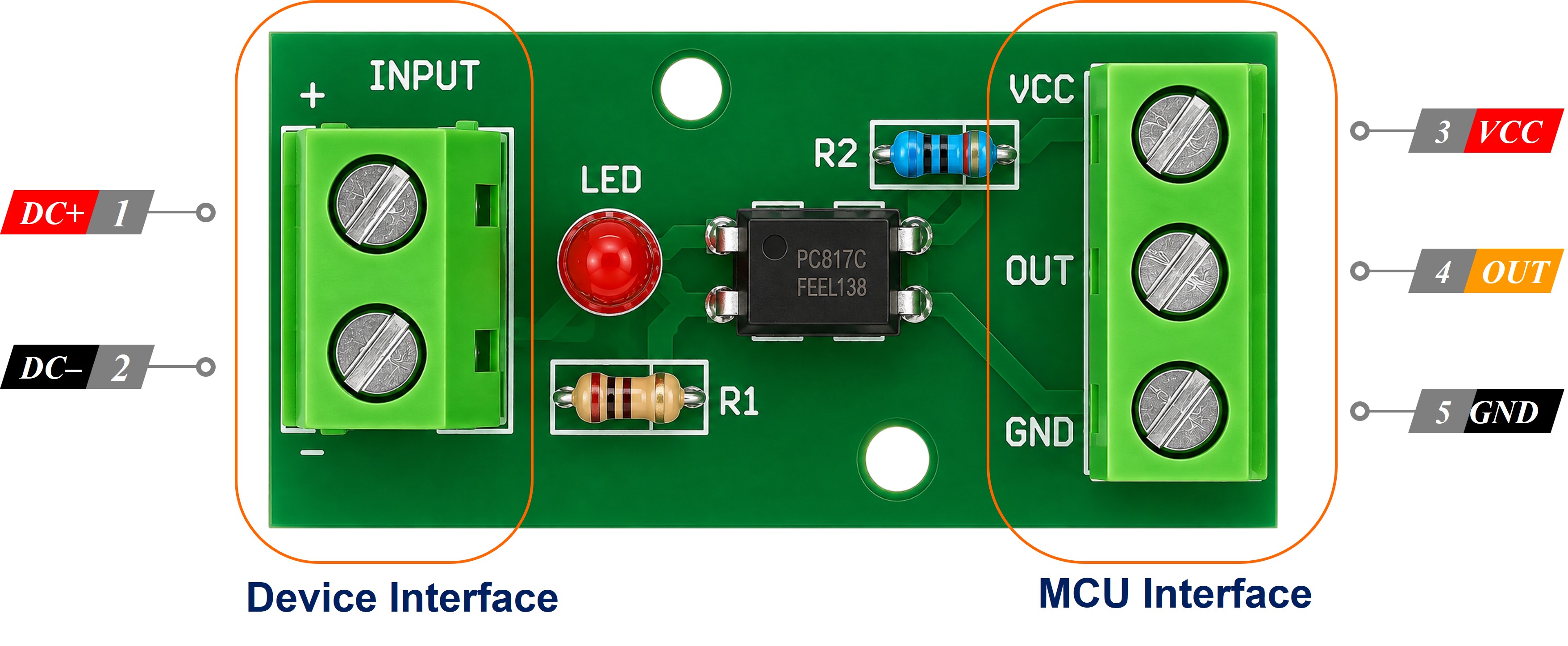
The PC817 is a 4-pin optocoupler, also called a photocoupler or an opto-isolator. Inside its plastic body there is an infrared LED facing a phototransistor across an insulating gap. When current flows through the LED, its light switches the transistor on, so the signal crosses as light instead of electricity. That is the whole reason the two sides stay electrically separate: nothing conducts from one side to the other.
A PC817 optocoupler module puts that chip on a small PCB together with the series resistor its LED needs, a status LED, screw terminals for the field wiring and a header for the board. For an Arduino Nano this means a 12V or a 24V line can be sensed as an ordinary digital input, while the Nano keeps its own 5V world untouched, and nothing has to be soldered or calculated.
Which PC817 Optocoupler Module Do I Need?
This is the one decision that has to be made before ordering, because the series resistor on the module is already fitted, and it is sized for a single input voltage. The modules are therefore sold as three separate variants, and they are not interchangeable:
- 12V optocoupler module - the one used everywhere in this tutorial. It suits an ignition feed, a headlight circuit, a door-switch line, a 12V relay coil, and anything else running on a car or motorcycle battery.
- 24V optocoupler module - for 24V DC signals: a contactor or solenoid coil in a machine cabinet, a PLC output, a truck or bus electrical system.
- 3-5V optocoupler module - for logic-level signals, both 3.3V and 5V. It is the one to buy when the point is to break a ground loop between two boards rather than to survive a high voltage.
Each variant is also sold in 1, 2, 4 and 8 channel versions, so a Nano hidden behind a dashboard can watch several lines from one small PCB - as long as every line on that PCB runs at the module's voltage.
WARNING
Do not run a module outside the voltage it was built for. A 12V module fed from a 24V line receives roughly double the current its internal LED was intended to carry, and it will be damaged. A 24V module fed from a 12V line is underdriven instead: its output may switch late, switch only sometimes, or never switch at all. Choosing the variant is the module's version of sizing a resistor, and it is just as unforgiving.
Specifications
These are the figures of the PC817 chip that sits at the heart of all three modules:
| Parameter | Value |
|---|---|
| Package | 4-pin DIP, pin 1 marked by a dot or a notch |
| LED forward voltage (Vf) | about 1.2V typical, 1.4V max |
| LED forward current (If) | 20mA continuous max, 5-20mA normal, 10mA is a good target |
| Collector-emitter voltage (VCEO) | 35V max |
| Collector current (IC) | 50mA max |
| Collector power dissipation | 150mW |
| Isolation voltage | 5000Vrms for 1 minute |
| Current Transfer Ratio (CTR) | 50% to 600% depending on rank (A 80-160%, B 130-260%, C 200-400%, D 300-600%) |
| Switching speed | rise time about 4us, fall time about 3us |
| Operating temperature | -30°C to +100°C |
The PC817 Optocoupler Module Pinout
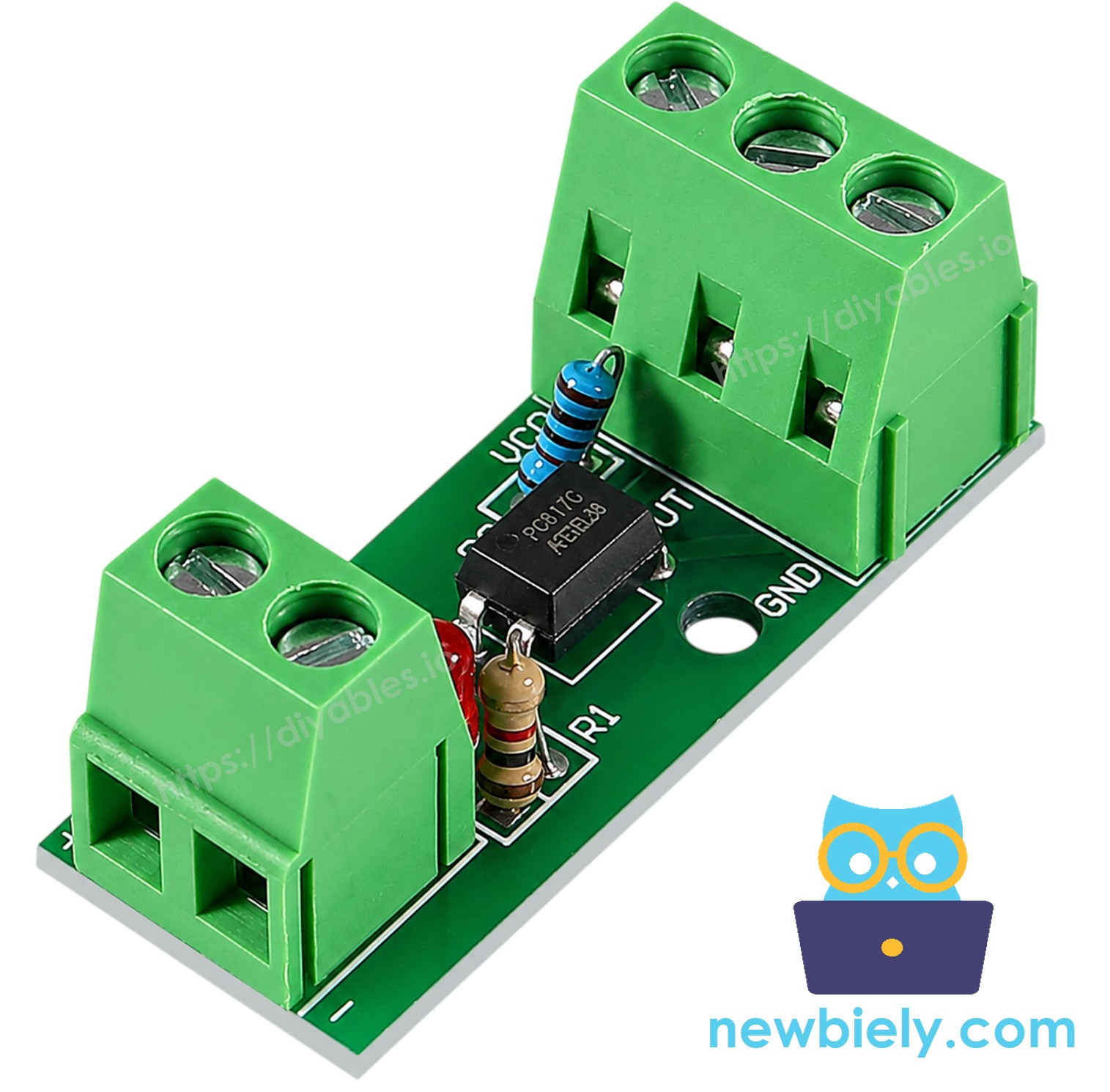
A single-channel module has two screw terminals on the isolated input side and a three-pin header on the Arduino Nano side.
- IN+ (or +) terminal: the positive of the input side. The 12V or 24V signal must be connected to this terminal. No series resistor is added here - the module already carries the one that matches its variant.
- IN- (or -) terminal: the negative of the input side. It must be connected to the ground of the 12V/24V circuit, NOT to the Arduino Nano GND.
- VCC pin: must be connected to the 5V pin of the Arduino Nano.
- GND pin: must be connected to a GND pin of the Arduino Nano.
- OUT pin: the isolated output, named DO or OUT1..OUTn on multi-channel boards. It must be connected to a digital input pin of the Arduino Nano.
WARNING
The IN- terminal and the GND pin look like they belong together, but they must never be joined. IN- belongs to the 12V/24V circuit and GND belongs to the Arduino Nano. Tying the two grounds together removes the isolation, and the gap between them is exactly what protects the board.
※ NOTE THAT:
The arrangement of the pins on a PC817 isolation module can differ from one manufacturer to another. Always trust the labels printed on the module rather than the position of a pin. Take a close look before wiring!
How Arduino Nano Reads the Isolated Signal
The OUT pin of the module goes to a digital input pin of the Arduino Nano that is configured with the internal pull-up. An external 10 kΩ resistor to 5V would do the same job, but the internal pull-up is simpler and costs nothing - the same trick used in the Arduino Nano - Button tutorial.
Inside the module the phototransistor sits between that pin and ground. When the external signal energizes the input LED, the transistor conducts and drags the pin down against the pull-up:
| External 12V/24V signal | Internal LED | Phototransistor | Arduino Nano pin reads |
|---|---|---|---|
| Present | on | conducting | LOW |
| Absent | off | not conducting | HIGH |
So a LOW on the pin means the external signal IS present. This is the opposite of what most beginners expect, and it must be inverted in the code. That is settled physics for a phototransistor wired straight to the pin, which is exactly how the bare chip behaves - but a module may add a twist, which brings us to the next section.
PC817 Optocoupler Module: Active-HIGH or Active-LOW?
The table above describes the raw phototransistor. Many modules leave it exactly like that, but some manufacturers add an inverting stage on the board, so the OUT pin instead follows the input and reads HIGH while the signal is present. Both kinds are sold under the same product photos, and no amount of reading the listing settles it. The reliable way is to spend one minute measuring your own module:
- Wire the module to the Arduino Nano as shown below, upload the sketch from this tutorial, and open the Serial Monitor.
- Leave the IN+ and IN- terminals unconnected and note what is printed.
- Now apply the 12V or 24V signal to those terminals and note what changes.
- Whichever reading appears while the signal is present is your module's active level. If that is LOW, your module is active-LOW; if it is HIGH, it is active-HIGH.
- Use the status LED on the module as a second opinion. That LED is driven from the input side, so it lights whenever the input terminals are energized. If the LED is lit and the Serial Monitor still says OFF, the polarity is the wrong way round, not the wiring.
Fixing it is a single edit. The sketch keeps the polarity in one constant near the top:
Leave it as true for an active-LOW module, which is the more common kind and the default here, and change it to false for an active-HIGH one. Nothing else in the code has to be touched.
Building It From the Bare PC817 Chip Instead
If you would rather solder the raw 4-pin chip onto your own perfboard, everything above still applies, except that the series resistor now has to be fitted by you.
Pin 1 is nearest the dot or the notch. Pin 1 - Anode (A) and Pin 2 - Cathode (K) form the input side: the signal must be connected to pin 1 through the series resistor, and pin 2 to the ground of that circuit. Pin 4 - Collector (C) must be connected to the Arduino Nano input pin, and Pin 3 - Emitter (E) to the Arduino Nano GND. The same rule holds here: pin 2 and pin 3 must never be joined.
The resistor value comes from R = (Vin - 1.2) / 0.01, aiming for 10mA through the internal LED, whose forward voltage is about 1.2V:
| Input voltage | Resistor to use | Power rating |
|---|---|---|
| 3.3V | 220Ω | 1/4W |
| 5V | 390Ω | 1/4W |
| 12V | 1 kΩ | 1/4W |
| 24V | 2.2 kΩ | 1/2W |
Leaving a 1 kΩ resistor on a 24V line pushes about 22.8mA through the LED, above the 20mA limit of the PC817. 3.3V is the practical floor, since the LED takes 1.2V of it on its own. A bare chip is always active-LOW, so MODULE_ACTIVE_LOW stays true.
Wiring Diagram
Wiring the PC817 Optocoupler Module to Arduino Nano
The 12V or 24V signal and its ground go into the IN+ and IN- screw terminals, while the VCC, GND and OUT header pins go to the Arduino Nano 5V, GND and pin 2.
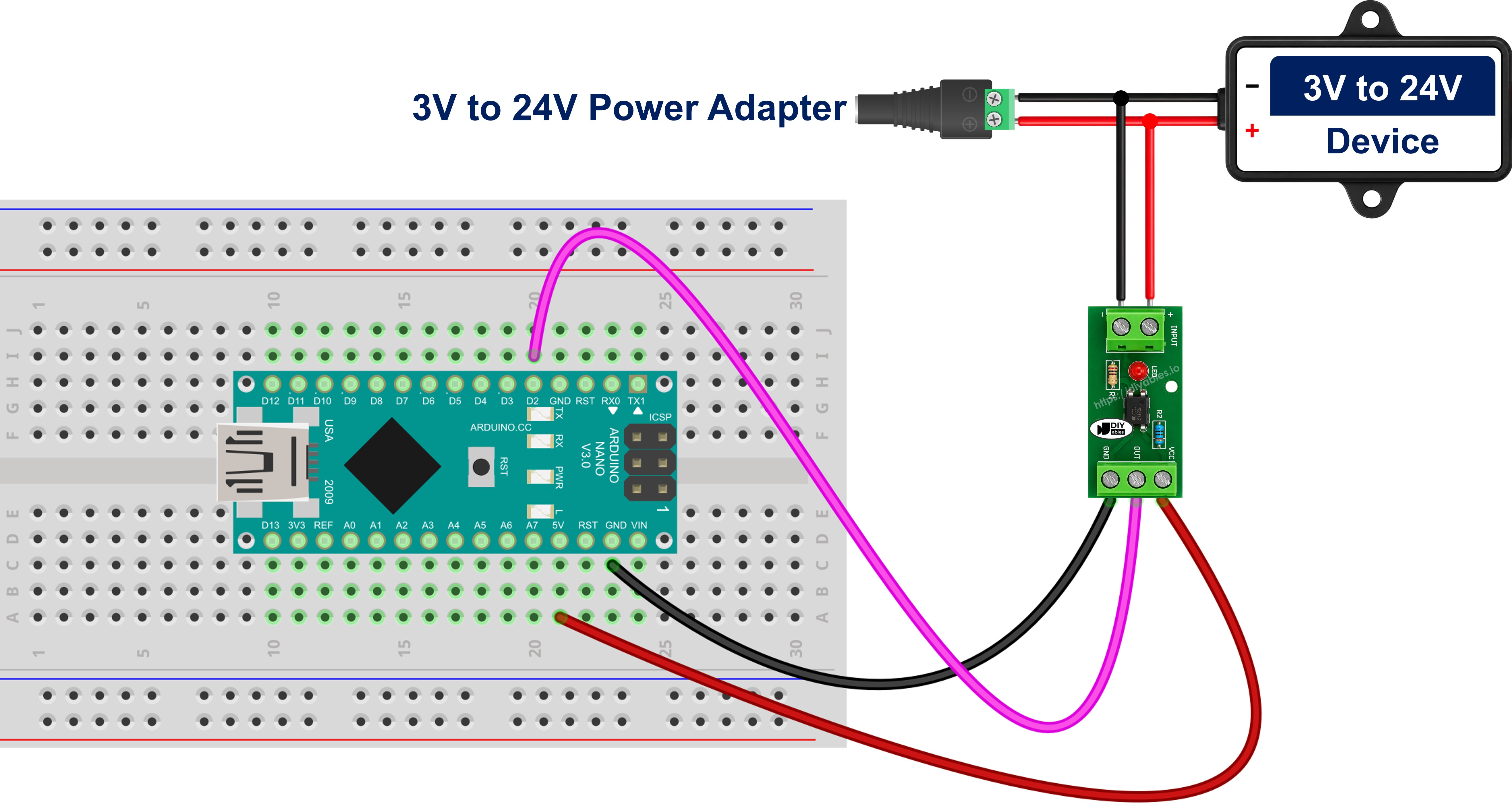
This image is created using Fritzing. Click to enlarge image
See The best way to supply power to the Arduino Nano and other components.
Wiring the Bare PC817 Chip to Arduino Nano
For the optional bare-chip build, the signal reaches pin 1 through its series resistor, the ground of that circuit returns to pin 2, and on the other side the chip's pin 4 goes to Arduino Nano pin 2 while the chip's pin 3 goes to Arduino Nano GND.
Wiring the PC817 in Parallel With a Device to Monitor It On or Off
Both diagrams above assume that a signal is handed to you on a convenient pair of wires. Inside a vehicle it never is. A headlight, an ignition feed, a door-switch line or a 24V contactor coil has no spare output to read, so the Arduino Nano has to tap the device itself.
The module input must be connected across the device, in parallel with it. It must never be placed in series with it. In series, the entire working current of the device - four or five amps for a headlight - would be forced through the tiny LED inside the PC817, and the part would be destroyed the moment the circuit was switched on. In parallel, nothing in the existing wiring is cut, opened or rerouted; two wires are simply added to terminals that are already there.
Taking a 12V headlight feed as the example, with the 12V module:
- The switched positive terminal of the lamp must be connected to the IN+ screw terminal of the module.
- The negative, return terminal of the same lamp must be connected to the IN- screw terminal.
- On the isolated side nothing changes: OUT must be connected to Arduino Nano pin 2, VCC to the Arduino Nano 5V, and GND to Arduino Nano GND.
No series resistor is fitted in either of those two wires - that is exactly what buying the variant that matches the line pays for. The tap draws about 10mA. Next to the 4 to 5A of a headlight, or the few hundred milliamps of a solenoid coil, that is nothing at all - the lamp behaves exactly as it did before, and the measurement stays read-only. Because the tap sits directly across the device, the reading follows the real state of that device rather than a command sent to it: it goes active when the driver operates the switch, when a body-control relay closes on its own, and it stays inactive when the lamp was asked for but never came on. That is what makes a run-hour counter, an idle-time log or a "did it actually start?" alert possible on a board this small.
One honest limitation: this tells you that the device is energized, not that it is doing its job. A seized blower motor, or a heater element with an open winding, still has the full voltage across its terminals and will still be reported as ON.
Three points decide whether the tap works the first time:
- Polarity. The input side of the PC817 is an LED, so it conducts in one direction only. Swap IN+ and IN- and nothing happens at all - the LED never lights, the status LED on the module stays dark, and the Arduino Nano pin never changes. Vehicles are full of switched-negative circuits, so confirm which of the two terminals is the positive one before anything is bolted down.
- Inductive loads need a clamp diode. A relay coil, a solenoid, a contactor, a valve or a small motor throws a large reverse-voltage spike back onto its own terminals at the instant it is switched off. The PC817 input LED withstands only 6V in reverse, so that spike is enough to kill it. Fit an ordinary diode in reverse-parallel directly across the two input terminals - diode cathode to IN+, diode anode to IN-. In normal operation it is reverse-biased and does nothing; on a spike it conducts and holds the reverse voltage well below one volt. A 1N4148 covers a small tap, a 1N4007 a heavier one.
- A leaky driver reports a false ON. Very little in a modern vehicle is still switched by a plain mechanical contact - a solid-state driver does the work instead, and many of those leak a small current even when they are off. The same is true of PLC transistor outputs, triac outputs and LED-lamp drivers. Enough leakage partly lights the PC817 LED, and the Arduino Nano then reports the device as ON while it is off. The symptom is unmistakable: a reading that never falls back to inactive. The cure is a bleeder resistor of about 4.7 kΩ to 10 kΩ fitted in parallel with the module input, so the leakage flows through the resistor instead of through the LED.
※ NOTE THAT:
This method is for DC only. The input of the PC817 is a single LED and therefore answers to one polarity, which makes it the wrong part for sensing an AC line. That job belongs to an optocoupler whose input stage carries two LEDs connected back to back.
How To Program For PC817 Optocoupler
The first step is to specify the Arduino Nano pin that is connected to the OUT pin of the PC817 optocoupler module. Pin 2 is used in this tutorial:
The next step is to state which way round the module switches. Most modules pull their output LOW while the input signal is present, so this is left as true unless the test described above says otherwise:
That pin is then configured as an internal pull-up input by using the pinMode() function:
The pin state is read by using the digitalRead() function:
The last step is to turn that raw reading into a yes-or-no answer, using the constant so that a module of either polarity is handled by the same line:
No library is required for this project.
Arduino Nano Code for PC817 Optocoupler
Detailed Instructions
- Wire the components as shown in the diagram.
- Connect the Arduino Nano board to your computer using a USB cable.
- Open Arduino IDE on your computer.
- Select the right board and port.
- Copy the code above and paste it into the Arduino IDE.
- Click the Upload button on the Arduino IDE to compile and upload the code to the Arduino Nano.
- Open the Serial Monitor.
- Apply the 12V or 24V signal to the input terminals, then remove it again.
- Check out the result on the Serial Monitor.
If the Serial Monitor reports ENERGIZED while nothing is applied and OFF while the signal is applied, your module is the active-HIGH kind. Set MODULE_ACTIVE_LOW to false in the code above and upload again.
Video Tutorial
Additional Knowledge
Once the module has been chosen over the bare chip, one question is left, and it has to be answered before the order is placed: which of the three variants belongs in this particular install? The signal voltage decides most of it, but not all of it - what happens when the wrong one arrives, and how many lines have to be watched, matter too.
| 3-5V module | 12V module | 24V module | |
|---|---|---|---|
| Signal it expects | 3.3V and 5V logic | 12V DC | 24V DC |
| Typical source on a Nano install | a second board, a sensor board with its own supply, a long low-voltage harness | ignition feed, headlights, door switch, 12V relay coil | contactor and solenoid coils, PLC outputs, truck and bus systems |
| Reason for isolating | to break a ground loop, not to survive a voltage | the vehicle ground is noisy and shared with the starter | cabinet ground carries switching spikes from other loads |
| If fed a higher voltage than it expects | damaged by anything much above logic level | damaged on a 24V line, roughly double its intended LED current | nothing higher is normally met in these installs |
| If fed a lower voltage than it expects | - | unreliable on a logic-level signal | silent failure on a 12V line, switching late or not at all |
| Fit for a hidden Nano install | bench and multi-board work, rarely the dashboard | the default choice behind a dashboard | machine cabinets, where mounting space is not scarce |
It is evident that the 12V variant is the one to reach for in the vehicle install this tutorial is built around, that the 24V variant belongs in the machine cabinet where the coils live, and that the 3-5V variant is bought for a different reason altogether - not because the voltage is dangerous, but because the ground is. Where several lines have to be watched from one hidden Nano, a multi-channel board of the correct variant is cheaper and tidier than several single-channel ones, provided every line on it runs at the same voltage; a Nano watching both a 12V door switch and a 24V coil needs two modules, not one.