
Arduino Nano - ACS712 Current Sensor
This tutorial instructs you how to use Arduino Nano to read how many amps flow through a wire, with the help of the ACS712 30A current sensor module. In detail, we will learn:
- How to connect Arduino Nano to the ACS712 current sensor and put the sensor in series with a 12V load
- How to program Arduino Nano to find the zero point by itself, then measure DC current in amps
- How to measure AC current (RMS value) with the same sensor
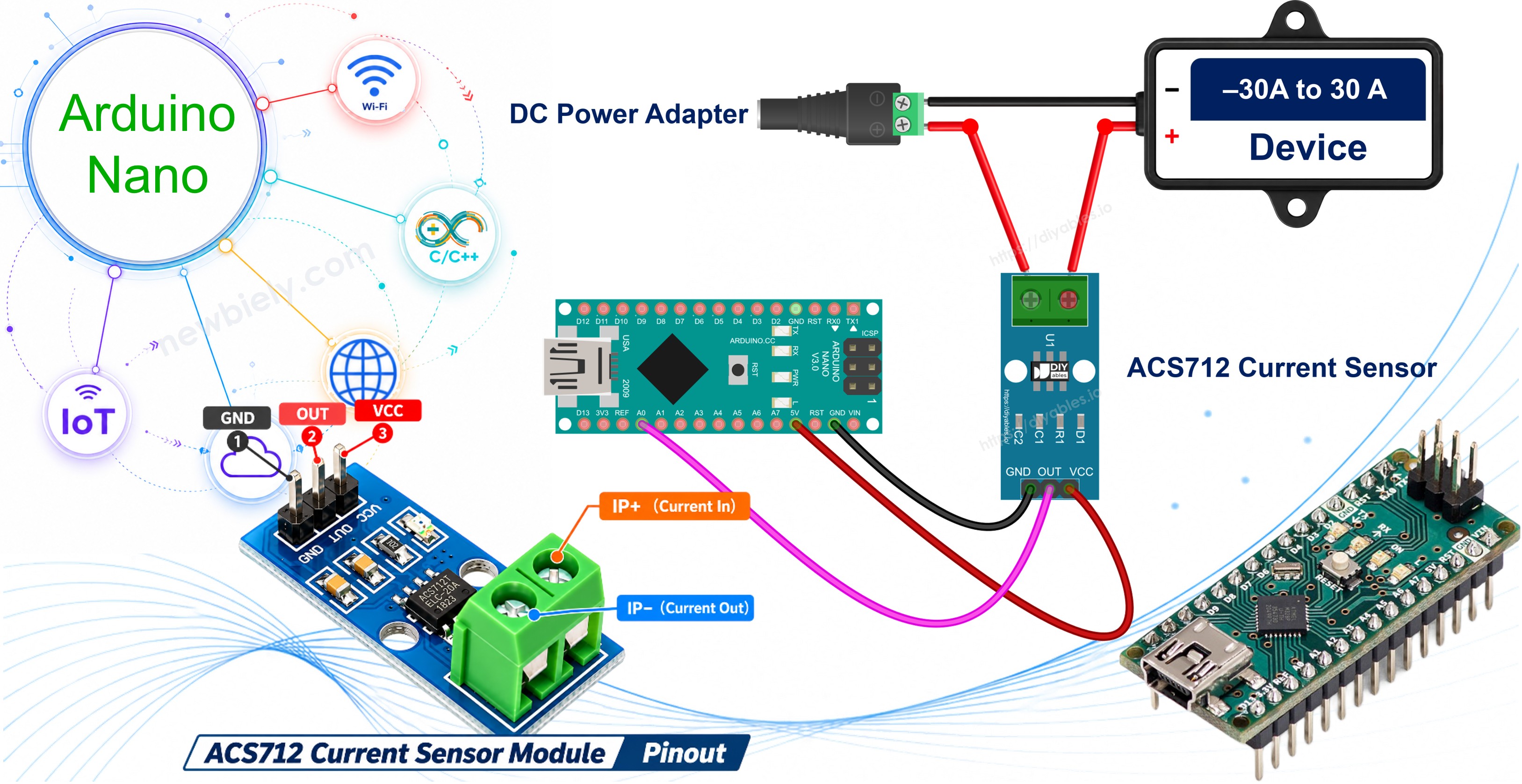
We suggest:
- Utilizing a voltage sensor if you are looking to measure the voltage of a battery or a power supply, not the current. With both sensors, you can also calculate the power (watts = volts × amps).
- Utilizing a MOSFET module if you are looking to switch or dim the 12V load that you measure here.
Hardware Preparation
Or you can buy the following kits:
| 1 | × | DIYables Sensor Kit (18 sensors/displays) |
Additionally, some of these links are for products from our own brand, DIYables .
Overview of ACS712 Current Sensor
The ACS712 Current Sensor Pinout
Inside the ACS712 chip, the measured current passes along a short, thick copper path. This current creates a magnetic field, and a Hall sensor placed right next to the copper turns the field into a voltage. The copper path has only about 1.2 mΩ of resistance, so it barely changes your circuit. Also, the high-current side is electrically isolated from the Arduino Nano side (2.1 kV RMS), so the Nano never touches the load wires.
The ACS712 chip comes in three current ranges. This tutorial uses the 30A version.
| ACS712 30A | |
|---|---|
| Chip | Allegro ACS712ELCTR-30A-T |
| Current range | −30A to +30A (DC or AC) |
| Sensitivity | 66 mV per amp |
| Other versions | 5A (185 mV/A), 20A (100 mV/A) |
| Supply voltage | 5V (4.5V to 5.5V) |
| Output at 0A | about 2.5V (half of VCC) |
| Output at +30A / −30A | about 4.48V / 0.52V |
| Bandwidth | 80 kHz |
| Total output error | about ±1.5% at 25°C |
| Isolation | 2.1 kV RMS |
| Copper path resistance | about 1.2 mΩ |
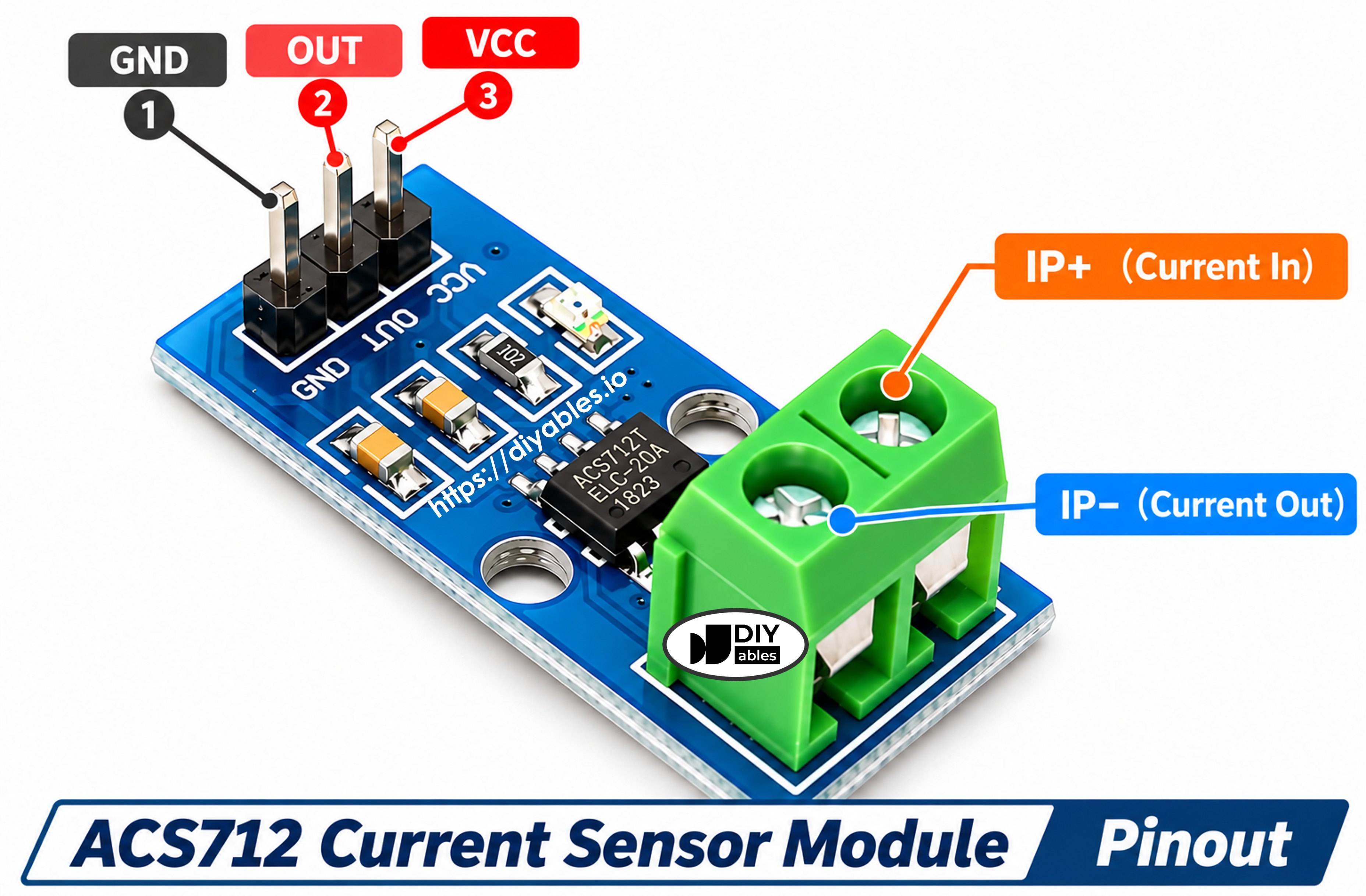
The module has a 3-pin header for the Arduino Nano side:
- VCC pin: must be connected to the 5V pin of Arduino Nano. Do not power it from 3.3V
- GND pin: must be connected to GND (0V)
- OUT pin: analog voltage output, must be connected to an analog input pin of Arduino Nano (A0 in this tutorial)
On the other side, there is a 2-pin screw terminal for the load current. On some boards these terminals have no label:
- IP+ terminal: the current enters here
- IP− terminal: the current leaves here
The two screw terminals must be connected in series with the load. Cut one supply wire of the load and put the terminal in between, so that all the load current flows through the sensor. A current from IP+ to IP− gives a positive value. The module also has a small LED that shows it is powered.
※ NOTE THAT:
The arrangement of pins on a module may differ from one manufacturer to another. It is essential to always refer to the labels printed on the module when using it. Take a close look!
How the Output Voltage Becomes Amps
With no current, the OUT pin sits at about 2.5V. For each amp that flows from IP+ to IP−, the output rises by 66 mV. For each amp in the other direction, it falls by 66 mV. So the formula is simple:
For example, if the zero point is 2.500V and the Nano reads 2.566V, the current is 0.066 / 0.066 = 1 A.
Vzero is almost never exactly 2.500V. Each module is a little different, so the code measures the real zero point at startup while no current flows. This is why the load must be OFF when you power up the Nano.
A few facts about accuracy on Arduino Nano:
- The Nano has a 10-bit ADC. With the 5V reference, one ADC step is about 4.9 mV. With 66 mV per amp, one step is about 74 mA. So this sensor works best for loads of about 0.5A or more, such as motors, lamps, LED strips and heaters.
- A reading of ±0.05A to ±0.1A with no load is normal noise. The code averages many readings to make it smaller.
- When the Nano is powered by USB, its 5V pin is often a bit lower than 5V, for example 4.8V. This is not a problem here: the ACS712 output is ratiometric (it scales with its supply), and the Nano ADC uses the same 5V as its reference, so the two changes cancel out.
Wiring Diagram
The sensor's 3-pin header goes to the Nano (VCC to 5V, GND to GND, OUT to A0), and its screw terminal is placed in the positive wire between the 12V adapter and the 12V DC device (such as a DC motor, LED strip or lamp).
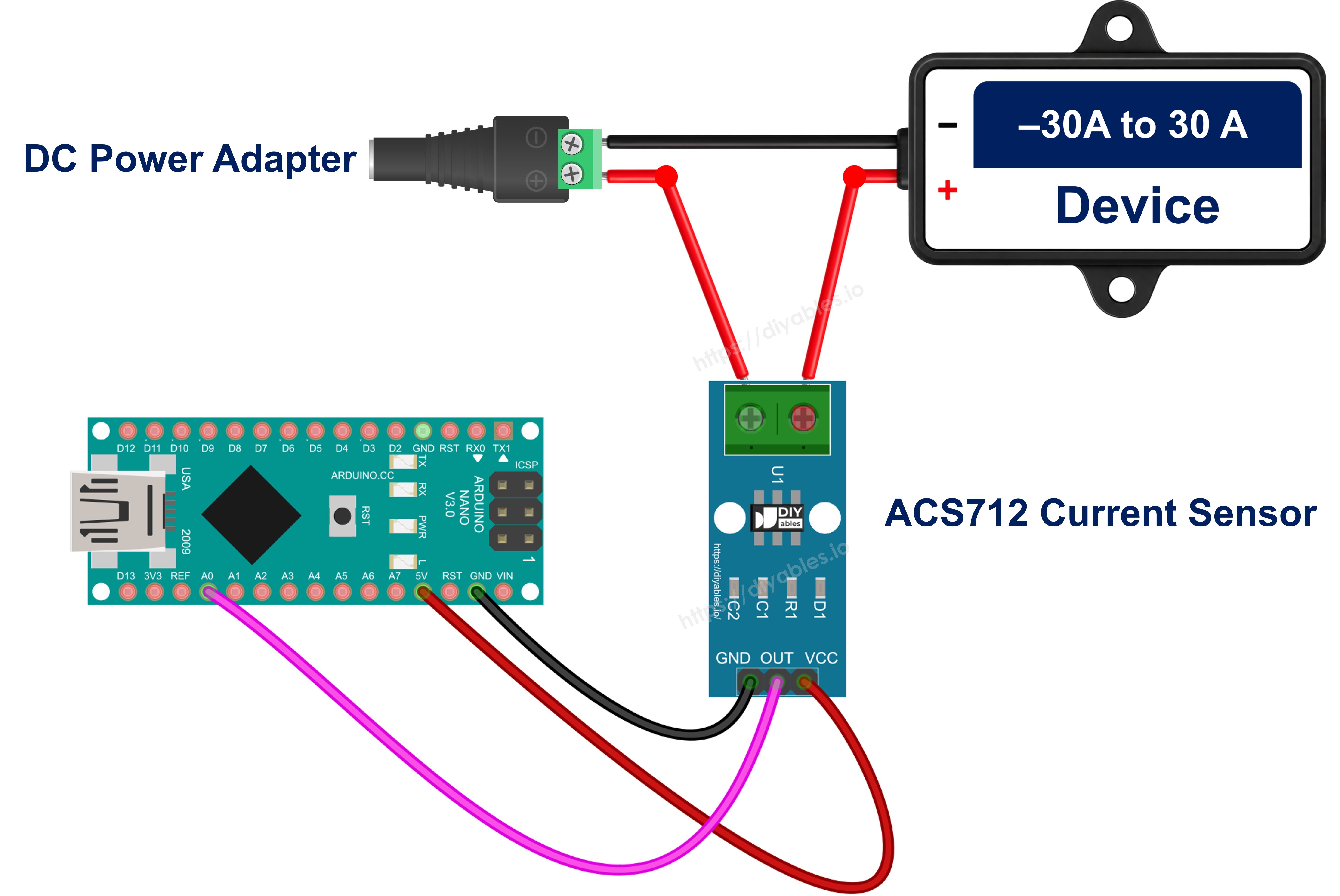
This image is created using Fritzing. Click to enlarge image
See The best way to supply power to the Arduino Nano and other components.
| From | To |
|---|---|
| ACS712 VCC | Arduino Nano 5V |
| ACS712 GND | Arduino Nano GND |
| ACS712 OUT | Arduino Nano A0 |
| 12V adapter + (via DC power jack) | ACS712 IP+ |
| ACS712 IP− | DC device + |
| DC device − | 12V adapter − (via DC power jack) |
The OUT pin goes directly to A0, with no resistor. The Nano is a 5V board, so its analog pins can accept the full 0.5V to 4.5V output of the sensor.
WARNING
The 12V wires go only to the screw terminal of the ACS712 and to the DC device. Never connect them to any pin of the Arduino Nano.
How To Program For ACS712 Current Sensor
No library is needed. The sensor gives a plain analog voltage, so analogRead() is enough.
- The first step is to specify the Arduino Nano pin that is connected to the OUT pin, and the sensitivity of the 30A version:
- Read the pin many times and convert the average to volts. The Nano ADC gives 0 to 1023 for 0V to 5V:
- In setup(), with the load OFF, save the zero point. 1000 readings give a stable value:
- In loop(), turn the voltage into amps with the formula above:
Arduino Nano Code for ACS712 Current Sensor - DC Current
The code below finds the zero point at startup. After that, every 0.5 seconds, it averages 200 readings and prints the OUT voltage and the current in amps.
Detailed Instructions
- If this is the first time you use Arduino Nano, see how to setup environment for Arduino Nano on Arduino IDE.
- Wire the components as shown in the diagram. Keep the 12V adapter unplugged for now.
- Connect the Arduino Nano board to your computer using a USB cable.
- Open Arduino IDE on your computer, then select the Arduino Nano board and its COM port.
- Copy the above code and paste it into Arduino IDE.
- Click the Upload button to upload the code to the Arduino Nano.
- Open the Serial Monitor and set the baud rate to 9600. Wait until the zero point is printed. The load must stay OFF during this time.
- Now plug in the 12V adapter. The DC device turns on.
- If your DC device is a motor, hold the motor shaft gently with your fingers for a moment and watch the current go up.
- See the result on the Serial Monitor:
The first lines show only noise, because the adapter is still unplugged. In this run, the DC device is a 12V DC motor. The value of 1.70A is the short start-up peak of the motor. The motor then settles near 0.9A, and the current rises to about 1.3A while you slow the shaft with your fingers.
If you see negative values while the DC device runs, the current flows from IP− to IP+. Swap the two wires on the screw terminal, or simply ignore the minus sign.
Measuring AC Current
An AC current changes direction many times per second (50 or 60 times, depending on your country). The OUT pin swings above and below the zero point, so the plain average is about zero and tells you nothing. In place of the average, we compute the RMS (root mean square) value, which is the number your multimeter shows for AC.
The code samples the sensor as fast as it can for 200 ms. This window covers 10 full cycles at 50 Hz or 12 cycles at 60 Hz. For each sample, it takes the distance from the zero point, squares it, and adds it up. At the end of the window:
The wiring on the Arduino Nano side stays the same. The screw terminal goes in series with one wire of the AC device.
WARNING
Mains AC (110V or 220V) is dangerous and can kill. Practice first with the low-voltage DC load above. The copper and screw side of the module carries the full mains voltage, so never touch the screw terminal or the load wires while the circuit is live. Put the module in a closed, non-conductive box before you plug in a mains device.
Arduino Nano Code for ACS712 Current Sensor - AC Current
Detailed Instructions
- Make sure the AC device is unplugged, then wire the screw terminal in series with it.
- Copy the code above and paste it into Arduino IDE.
- Click the Upload button to upload the code to Arduino Nano.
- Open the Serial Monitor and wait for the zero point.
- Turn on the AC device, for example a hair dryer on its low setting, without touching the module.
With the device OFF, the RMS value is not exactly 0. The noise is squared, so it can never cancel out, and a small value like 0.07A remains. Treat anything under about 0.1A as zero.
Additional Knowledge
ACS712 5A vs 20A vs 30A: Which One to Choose
All three versions have the same pins, the same wiring and the same code. Only the SENSITIVITY value in the code changes.
| ACS712 5A | ACS712 20A | ACS712 30A | |
|---|---|---|---|
| Current range | ±5A | ±20A | ±30A |
| Sensitivity | 185 mV/A | 100 mV/A | 66 mV/A |
| SENSITIVITY in code | 0.185 | 0.100 | 0.066 |
| One Arduino Nano ADC step (4.9 mV) | about 26 mA | about 49 mA | about 74 mA |
It is evident that the 5A version gives the finest steps for small loads, while the 30A version is the right pick when the current can go above 20A. Choose the smallest range that still covers the largest current of your project.