
Arduino Nano - DRV8833 DC Motor Driver
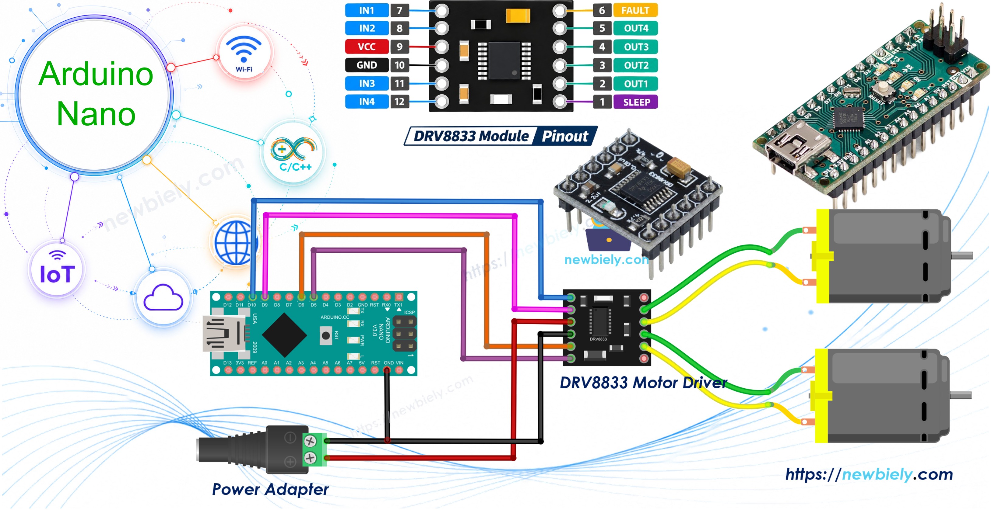
This tutorial instructs you how to use Arduino Nano with the DRV8833 motor driver module to spin small DC motors. In detail, we will learn:
- How the DRV8833 decides the direction and speed of a motor from just two input pins
- How to connect Arduino Nano, the DRV8833 module and one DC motor
- How to program Arduino Nano to speed up, reverse, coast and brake one DC motor
- How to extend the circuit and the code to drive two DC motors, like the wheels of a small robot car
We suggest:
- Utilizing the L298N driver if your motors need a supply above 10.8V, such as 12V gear motors.
- Utilizing the DRV8833 (this tutorial) if your project runs from a few AA cells or a 5V adapter, since it wastes much less power as heat.
Hardware Preparation
Or you can buy the following kits:
| 1 | × | DIYables Sensor Kit (18 sensors/displays) |
Additionally, some of these links are for products from our own brand, DIYables .
Overview of DRV8833 Motor Driver
The DRV8833 Motor Driver Pinout
The DRV8833 is a dual H-bridge chip from Texas Instruments. One module can run two brushed DC motors on their own (it can also run one bipolar stepper motor, but that is outside this tutorial). The motor supply must be between 2.7V and 10.8V. Each channel delivers around 1.5A continuously and up to 2A for short peaks when it stays cool. Its outputs are MOSFETs with a low on-resistance (about 360 mΩ), so the voltage loss is small and the board stays much cooler than an L298N. This makes it a good choice for battery robots in the 3V to 9V range. The chip also protects itself against under-voltage, over-current and over-heating.
There is no separate logic power pin: the chip creates its own internal logic voltage from VCC. Therefore, the 5V signals coming out of the Arduino Nano are accepted directly.
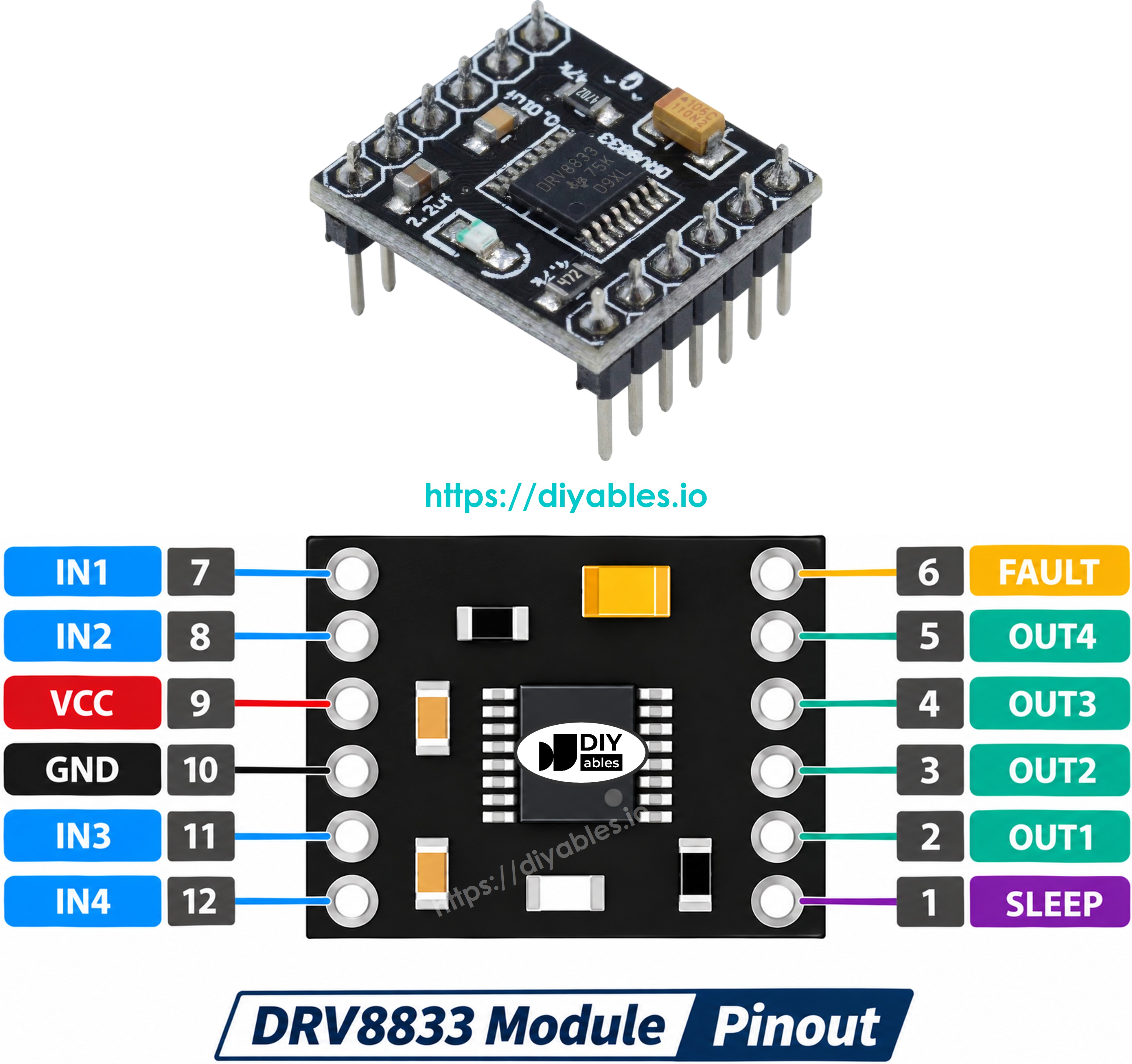
The DRV8833 module has twelve pins:
- VCC pin: must be connected to the motor power supply (2.7V to 10.8V)
- GND pin: must be connected to GND of the motor power supply AND GND of the Arduino Nano
- EEP pin (nSLEEP): must be pulled HIGH to wake the driver up. Connect it to the 5V pin of the Arduino Nano. If it is LOW, the chip sleeps and the motors do not move
- ULT pin (nFAULT): fault output. It goes LOW when the chip detects a problem. This pin is optional and can be left unconnected
- IN1, IN2 pins: control inputs of motor A, used for both direction and speed
- IN3, IN4 pins: control inputs of motor B, used for both direction and speed
- OUT1, OUT2 pins: must be connected to the two wires of motor A
- OUT3, OUT4 pins: must be connected to the two wires of motor B
※ NOTE THAT:
The arrangement and labels of pins may differ from one manufacturer to another. Some boards print AIN1/AIN2/BIN1/BIN2, AOUT1/AOUT2/BOUT1/BOUT2, SLP and FLT instead of the names above. It is essential to always refer to the labels printed on the module when using it. Take a close look!
How the DRV8833 Controls a Motor
Unlike the L298N, the DRV8833 has no ENA or ENB speed pin. The two IN pins of a channel set both the direction and the speed. The table below shows motor A (motor B works the same way with IN3 and IN4):
| IN1 | IN2 | Motor A |
|---|---|---|
| LOW | LOW | Coast (the motor spins down freely) |
| HIGH | LOW | Forward |
| LOW | HIGH | Reverse |
| HIGH | HIGH | Brake (the motor stops quickly) |
To change the speed, a PWM signal is sent to one of the two pins while the other stays LOW:
- Forward with speed: PWM on IN1, IN2 = LOW
- Reverse with speed: IN1 = LOW, PWM on IN2
Because either pin may carry PWM, both IN pins of each channel must be connected to PWM-capable pins of the Arduino Nano. On the Arduino Nano, these pins are D3, D5, D6, D9, D10 and D11. If you want to brush up on how a DC motor and PWM work, see the Arduino Nano - DC Motor tutorial.
※ NOTE THAT:
- Never power the motors from the 5V pin of the Arduino Nano. Use an external supply such as a 5V adapter or a pack of 4 AA batteries (about 6V).
- The GND of the motor supply, the DRV8833 module and the Arduino Nano must be connected together. Without a common ground, the motors will behave strangely.
- For heavier loads, the two channels can be wired in parallel for about 3A, but this is optional and not covered here.
Control One DC Motor with Arduino Nano and DRV8833
Wiring Diagram
The motor A wires go to OUT1 and OUT2, and the Arduino Nano drives IN1 from pin D10 and IN2 from pin D9.
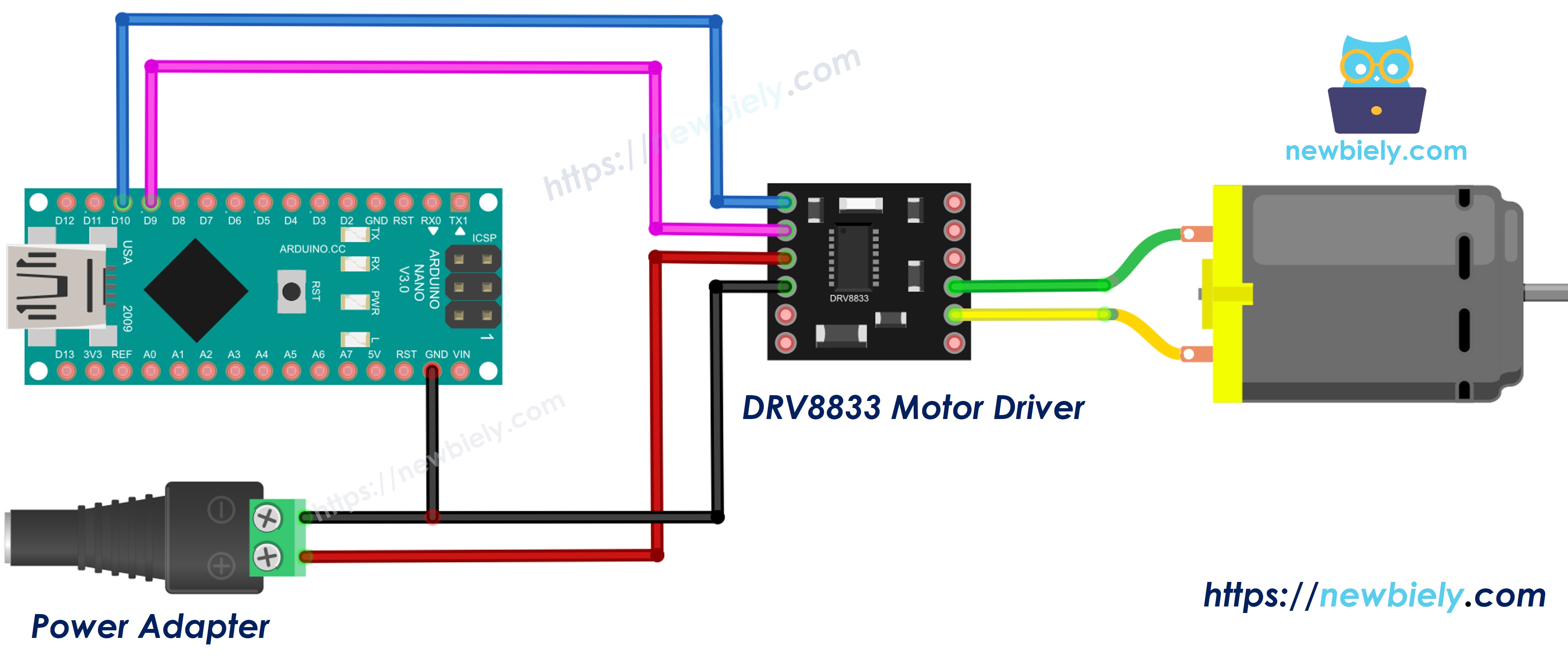
This image is created using Fritzing. Click to enlarge image
| DRV8833 Module | Arduino Nano / Power |
|---|---|
| IN1 | D10 |
| IN2 | D9 |
| EEP | 5V |
| GND | GND (shared with the power supply) |
| VCC | + of the 5V power adapter (via DC power jack) |
| OUT1, OUT2 | Motor A wires |
How To Program For DRV8833
- The first step is to specify the Arduino Nano pins that are connected to IN1 and IN2:
- Set both pins as outputs in setup():
- To spin forward at a chosen speed (0 to 255), send PWM to IN1 and keep IN2 LOW:
- To spin in reverse, swap the roles of the two pins:
- To brake, set both pins HIGH. To coast, set both pins LOW:
Arduino Nano Code for DRV8833 - One DC Motor
The sketch below repeats these steps: it speeds the motor up, holds full speed, lets it coast, runs it in reverse, and finally brakes. Each step is printed to the Serial Monitor.
Detailed Instructions
- If this is the first time you use Arduino Nano, see how to setup environment for Arduino Nano on Arduino IDE.
- Wire the components as shown in the diagram. Keep the 5V adapter unplugged for now.
- Connect the Arduino Nano board to your computer using a USB cable.
- Open Arduino IDE on your computer, then select the Arduino Nano board and its COM port.
- Copy the code above and paste it into Arduino IDE.
- Click the Upload button to upload the code to Arduino Nano.
- Plug in the 5V adapter to power the motor.
- Open the Serial Monitor and set the baud rate to 9600.
- Watch the motor: it ramps up, keeps spinning, slowly rolls to a stop, turns the other way, and then stops sharply when it brakes.
※ NOTE THAT:
If the motor turns the "wrong" way when the Serial Monitor says Forward, simply swap the two motor wires on OUT1 and OUT2.
Control Two DC Motors with Arduino Nano and DRV8833
Wiring Diagram
For the second motor, add four wires: motor B goes to OUT3 and OUT4, IN3 goes to pin D6 and IN4 goes to pin D5. The rest of the wiring stays the same.
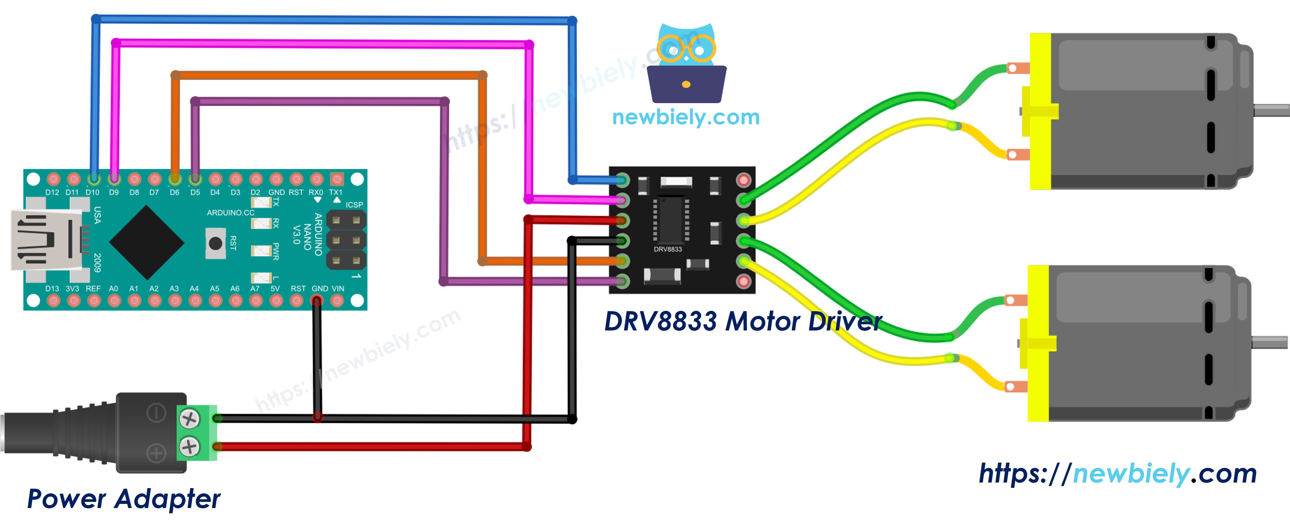
This image is created using Fritzing. Click to enlarge image
See The best way to supply power to the Arduino Nano and other components.
| DRV8833 Module | Arduino Nano / Power |
|---|---|
| IN1 | D10 |
| IN2 | D9 |
| IN3 | D6 |
| IN4 | D5 |
| EEP | 5V |
| GND | GND (shared with the power supply) |
| VCC | + of the 5V power adapter (via DC power jack) |
| OUT1, OUT2 | Motor A (left wheel) |
| OUT3, OUT4 | Motor B (right wheel) |
Arduino Nano Code for DRV8833 - Two DC Motors
Think of the two motors as the left and right wheels of a small robot car. The code uses two helper functions, motorA(speed) and motorB(speed). The speed is a signed number from -255 to 255: a positive value turns the wheel forward, a negative value turns it backward, and 0 lets it coast. With these two functions, the car can move forward, move backward, turn left, turn right and stop.
Detailed Instructions
- Wire the second motor as shown in the diagram.
- Connect the Arduino Nano board to your computer using a USB cable.
- Copy the code above and open it in Arduino IDE.
- Click the Upload button to upload the code to Arduino Nano.
- Plug in the 5V adapter.
- Open the Serial Monitor and watch both motors.
- To turn left, motor A runs backward while motor B runs forward. To turn right, it is the opposite.
Additional Knowledge
Let's compare the DRV8833 and the L298N motor drivers.
| DRV8833 | L298N | |
|---|---|---|
| Motor voltage | 2.7V to 10.8V | 5V to 35V |
| Current per channel | about 1.5A (2A peak) | about 2A |
| Switching parts | MOSFET | bipolar transistor |
| Voltage loss and heat | small | large |
| Speed control pin | no, PWM goes to IN pins | yes, ENA and ENB |
| Logic power | made inside the chip | separate 5V pin |
| Board size | very small | large with heatsink |
It is evident that the DRV8833 is the better fit for small, low-voltage battery robots, while the L298N is still needed for 12V or higher motors.