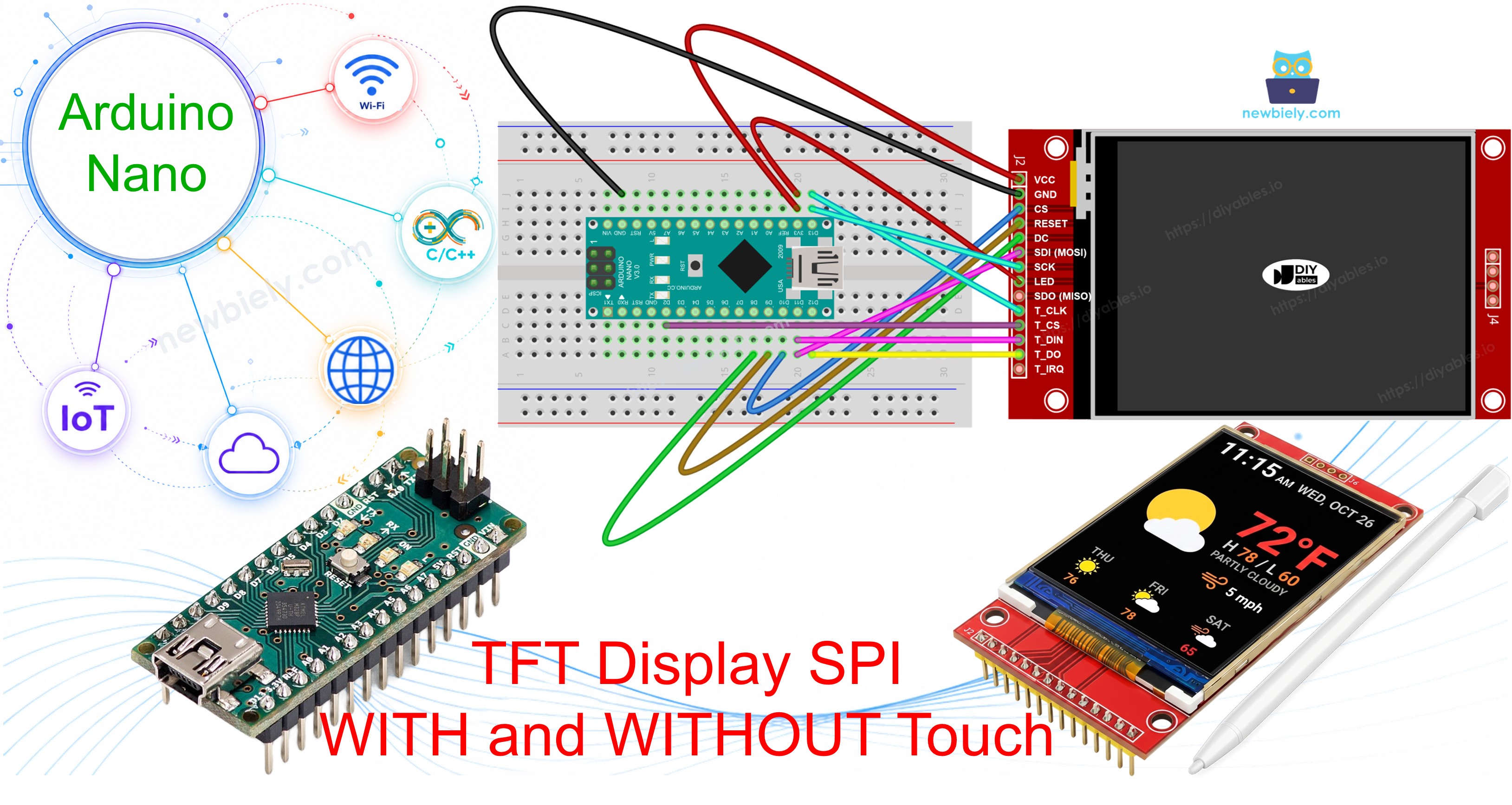
This walkthrough takes you step by step through using an SPI TFT display on the Arduino Nano. The Nano packs the same ATmega328P as the Uno into a compact, breadboard-friendly package - it has the same hardware SPI pins, so TFT wiring is identical to the Uno. The main limitation to keep in mind is the 2KB of SRAM: avoid large in-memory bitmaps and use PROGMEM for image data.
What you will walk through:
Wiring an SPI TFT display to the Arduino Nano.
Drawing shapes, lines, and filled areas.
Displaying text and numbers at multiple sizes.
Drawing bitmap images from program memory (PROGMEM).
Drawing bitmap images loaded from an SD card.
Rendering text with a custom external font.
Reading raw touch coordinates from an XPT2046 controller.
Drawing on screen by touch drag.
Creating interactive touch buttons.
Calibrating the touch screen.
Using a secondary or custom SPI bus for the display.
This walkthrough covers both touch and non-touch SPI TFT LCD displays. It works with 1.3, 1.54, 2.2, 2.4, 2.8, 3.2, and 3.5 inch panels driven by ILI9341, ILI9488, or ST7789 controller chips.
Disclosure: Some of the links provided in this section are Amazon affiliate links. We may receive a commission for any purchases made through these links at no additional cost to you. Additionally, some of these links are for products from our own brand, DIYables .
What Is the SPI TFT Display?
An SPI TFT display module is a color LCD panel driven by a controller chip over a 4-wire SPI bus. The DIYables_TFT_SPI library supports three popular driver chips:
ILI9341 - 16-bit RGB565 color, up to 40 MHz SPI.
ILI9488 - 18-bit RGB666 color over SPI, up to 24 MHz.
ST7789 - 16-bit RGB565 color, up to 40 MHz SPI.
Recommendation: If you have not yet purchased a display, we recommend the ST7789 driver. It is widely available, runs at full 40 MHz SPI speed, and is the most straightforward choice for new projects.
All drawing is done through the Adafruit GFX API, which provides shapes, text, fonts, and bitmap output.
Pinout
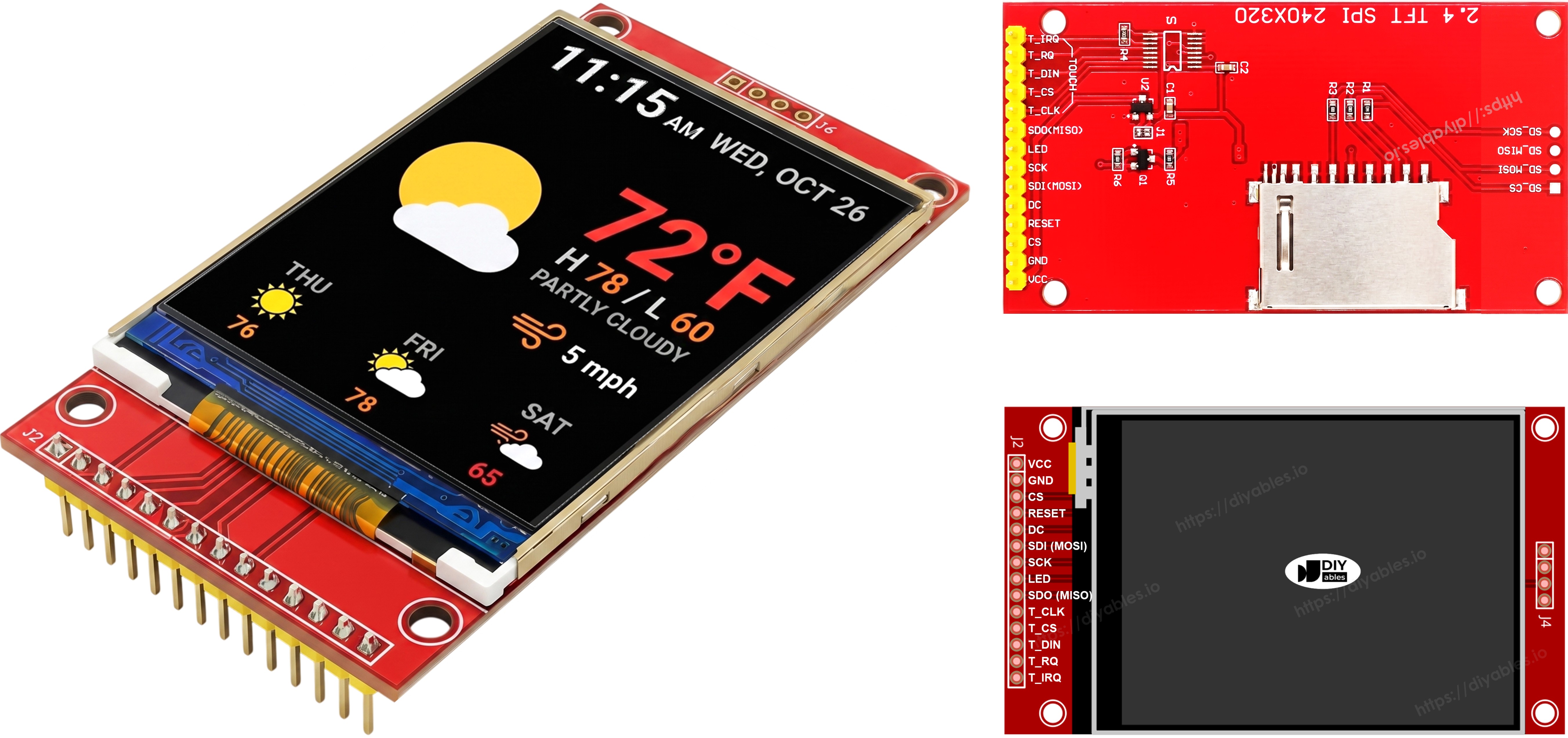
Most SPI TFT LCD displays have the following pins:
Display pins:
Pin
Function
VCC
Power supply
GND
Ground
CS
Chip Select — pulled low to select the display on the SPI bus
DC / RS
Data / Command select — high for pixel data, low for commands
RST
Hardware reset — optional; tie to 3.3V if unused
MOSI / SDI / SDA
SPI data in (MCU → display)
SCK / CLK
SPI clock
MISO / SDO
SPI data out (display → MCU) — optional for display-only use
LED / BL / BLK
Backlight power — connect to 3.3V or a PWM pin for dimming
SD card pins (if your application needs to access the SD card):
Pin
Function
SD_CS / TF_CS
SD card Chip Select
MOSI / SDI
MOSI — data from MCU to SD card
SCK / CLK
SCK — SPI clock
MISO / SDO
MISO — data from SD card to MCU
For TFT displays that support touch, there are additional touch pins (if your application uses the touch function and the display supports it):
Pin
Function
T_CS
Touch controller Chip Select
T_CLK
SCK — SPI clock
T_DIN
MOSI — data from MCU to touch controller
T_DO
MISO — data from touch controller to MCU
T_IRQ
Touch interrupt — optional; signals when the screen is being touched
Note: Some non-touch display modules also expose T_CS, T_CLK, T_DIN, T_DO, and T_IRQ pins. These are non-functional on those boards — the touch controller IC is not populated. They appear because the PCB reuses the same layout as the touch-enabled version to reduce manufacturing variants.
Wiring Diagram
Note — level converter optional: These SPI TFT display modules include on-board level shifting on their signal lines, so the 5V logic from the Arduino Nano can drive MOSI, SCK, CS, DC, RST, and T_CS (if using touch) directly — this wiring is tested and works. For a permanent build, adding a 5V to 3.3V Level Converter on the MCU-driven signal lines is still the safer choice for long-term reliability. The MISO line (display → MCU) never needs one.
Note — SDO (MISO) is optional: The SDO (MISO) line only carries data from the display back to the board. None of the example code in this tutorial reads from the display, so this pin can be left unconnected. On modules where the touch controller shares the same SPI bus, a connected SDO line can interfere with communication, so leaving it unconnected is recommended.
Without Touch
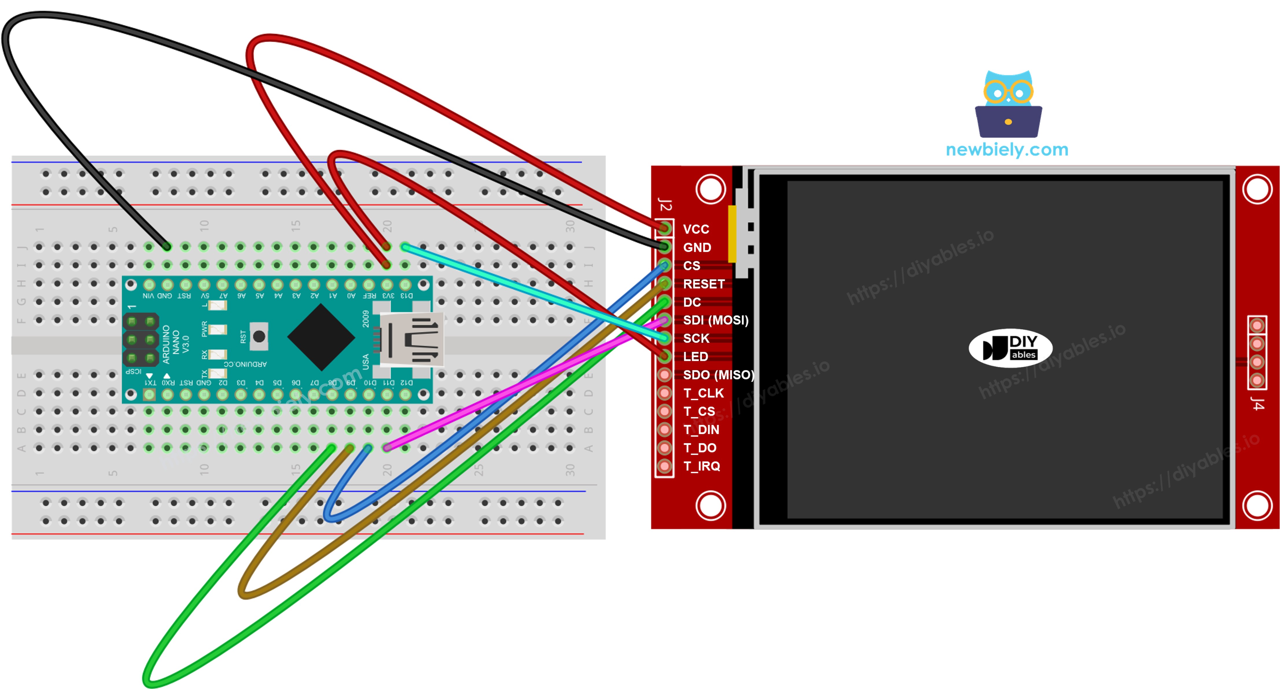
Connect MOSI to D11, SCK to D13, MISO to D12 on the Nano. CS, DC, and RST can be any available GPIO — D10, D8, D9 are used in the examples.
Display:
TFT Pin
Arduino Nano Pin
Description
VCC
3.3V
Power supply (3.3V only — the display runs at 3.3V)
GND
GND
Ground
CS
D10
Chip Select
DC / RS
D8
Data / Command select
RST
D9
Reset (optional)
MOSI / SDI
D11
Hardware SPI MOSI
SCK
D13
Hardware SPI clock
MISO / SDO
D12
Hardware SPI MISO (optional)
LED / BL
3.3V
Backlight power
SD card (if your application needs to access the SD card):
SD Pin
Arduino Nano Pin
Description
SD_CS / TF_CS
any free GPIO
SD card Chip Select
MOSI / SDI
D11
Shared with display MOSI (D11)
SCK / CLK
D13
Shared with display SCK (D13)
MISO / SDO
D12
Shared with display MISO (D12)
This image is created using Fritzing. Click to enlarge image
With Touch
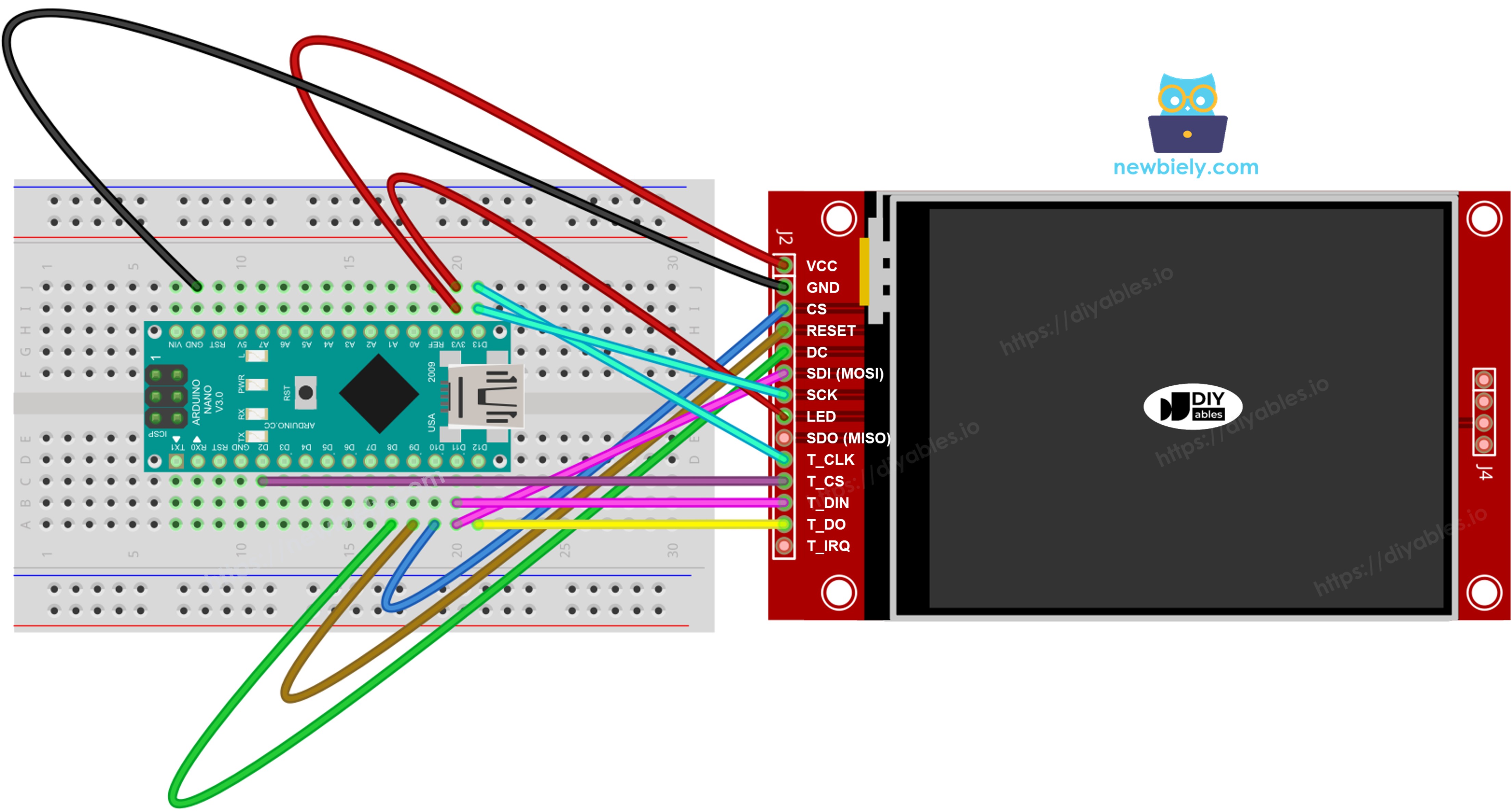
Connect the XPT2046 touch controller to the Arduino Nano SPI bus, sharing D11, D13, and D12 with the display.
Display:
TFT Pin
Arduino Nano Pin
Description
VCC
3.3V
Power supply (3.3V only — the display runs at 3.3V)
GND
GND
Ground
CS
D10
Chip Select
DC / RS
D8
Data / Command select
RST
D9
Reset (optional)
MOSI / SDI
D11
Hardware SPI MOSI
SCK
D13
Hardware SPI clock
MISO / SDO
D12
Hardware SPI MISO (optional)
LED / BL
3.3V
Backlight power
Touch controller (if your application uses the touch function and the display supports it):
Touch Pin
Arduino Nano Pin
Description
T_CS
any free GPIO
Touch Chip Select
T_IRQ
any free GPIO
Touch interrupt (optional)
T_DIN
D11
Shared with display MOSI (D11)
T_CLK
D13
Shared with display SCK (D13)
T_DO
D12
Shared with display MISO (D12)
This image is created using Fritzing. Click to enlarge image
If your MCU has two or more hardware SPI interfaces, you can assign each peripheral (display, SD card, touch controller) to its own dedicated SPI bus. If your MCU has only one hardware SPI interface, all three peripherals share the same three data lines (MOSI, SCK, MISO) — on the Nano these are D11, D13, and D12. Each peripheral has its own CS pin, so only one is active at a time. The DIYables_TFT_SPI library manages both the display and the XPT2046 touch controller through a single API — no separate SPI library is needed for the touch side.
Setting Up the Library
Plug the Arduino Nano into your computer with a Mini-B USB cable.
Open Arduino IDE. Set the board to Arduino Nano and select the matching port.
Go to the Libraries panel on the left.
Type "DIYables_TFT_SPI" in the search box. Look for the library from DIYables.
Click Install. When asked, install all dependencies.
Search for DIYables TFTSPI created by DIYables.io and click the Install button.
Newbiely | Arduino IDE 2.3.8
──
☐
✕
File
Edit
Sketch
Tools
Help
Arduino Nano
Library Manager
DIYables TFT SPI
Type:
All
Topic:
All
DIYables TFT SPIby DIYables.io
Works with both touch and non-touch versions of the same SPI TFT modules. Supports ILI9341 (240x320, 16-bit RGB565), ILI9488 (320x480, 18-bit RGB666), and ST7789 (240x320, 16-bit RGB565) displays over SPI. Includes built-in driver for XPT2046 / HR2046 / ADS7843 SPI touch controllers and 4-wire resistive touch panels - no separate touch library required. Use the display-only API for non-touch panels, or add initTouchSPI() to enable touch on modules that include a touch controller. Extends Adafruit GFX for full graphics support. Works with any Arduino-compatible board that has SPI.
More info
1.0.3
INSTALL
Newbiely.ino
···
1
voidsetup() {
Output
Serial Monitor
Ln 1, Col 1
Arduino Nano on COM15
1
Note: If your Nano uses an older bootloader, select ATmega328P (Old Bootloader) under Processor in the Tools menu.
Foundation Code
Every sketch built with the DIYables_TFT_SPI library starts from this foundation:
#include <DIYables_TFT_SPI.h>#define TFT_CS_PIN 10#define TFT_DC_PIN 8#define TFT_RST_PIN 9// Uncomment the line that matches your driver chip:// DIYables_ILI9341_SPI TFT_display(240, 320, TFT_CS_PIN, TFT_DC_PIN, TFT_RST_PIN);// DIYables_ILI9488_SPI TFT_display(320, 480, TFT_CS_PIN, TFT_DC_PIN, TFT_RST_PIN);DIYables_ST7789_SPI TFT_display(240, 320, TFT_CS_PIN, TFT_DC_PIN, TFT_RST_PIN);voidsetup() {TFT_display.begin();TFT_display.setRotation(1);}voidloop() {// drawing code here}
Pass the panel's physical pixel dimensions to the constructor. A wrong size causes the image to be clipped or shifted.
Arduino Nano Code - Draw Shapes
The DrawShapes example draws circles, triangles, rectangles, rounded rectangles, and lines using the Adafruit GFX primitives.
/* * This Arduino Nano code was developed by newbiely.com * * This Arduino Nano code is made available for public use without any restriction * * For comprehensive instructions and wiring diagrams, please visit: * https://newbiely.com/tutorials/arduino-nano/arduino-nano-tft-lcd-touch-display-spi *//* Created by DIYables This example code is in the public domain Product page: https://diyables.io*/// =============================================// Single include brings in the base class plus all driver classes.// =============================================#include <DIYables_TFT_SPI.h>// =============================================// Wiring (Arduino Uno / Nano)// ---------------------------------------------// TFT module Arduino Uno / Nano// ------------ ---------------------------------// VCC -> 5V// GND -> GND// CS -> D10 (TFT_CS_PIN)// RESET -> D9 (TFT_RST_PIN)// DC / RS -> D8 (TFT_DC_PIN)// SDI / MOSI -> D11 (hardware SPI MOSI)// SCK -> D13 (hardware SPI SCK)// LED -> 3.3V (or any GPIO via initBacklight)// SDO / MISO -> D12 (only needed when reading from display)// =============================================// =============================================// SPI pin definitions (adjust for your board)// =============================================#define TFT_CS_PIN 10#define TFT_DC_PIN 8#define TFT_RST_PIN 9// Panel resolution in native (portrait) orientation - change to match your module#define TFT_WIDTH 240#define TFT_HEIGHT 320// MOSI and SCK use default hardware SPI pins// =============================================// Create display object (uncomment matching driver)// =============================================// DIYables_ILI9341_SPI TFT_display(TFT_WIDTH, TFT_HEIGHT, TFT_CS_PIN, TFT_DC_PIN, TFT_RST_PIN);// DIYables_ILI9488_SPI TFT_display(TFT_WIDTH, TFT_HEIGHT, TFT_CS_PIN, TFT_DC_PIN, TFT_RST_PIN);DIYables_ST7789_SPI TFT_display(TFT_WIDTH, TFT_HEIGHT, TFT_CS_PIN, TFT_DC_PIN, TFT_RST_PIN);#define BLACK DIYables_TFT_SPI::colorRGB(0, 0, 0)#define BLUE DIYables_TFT_SPI::colorRGB(0, 0, 255)#define RED DIYables_TFT_SPI::colorRGB(255, 0, 0)#define GREEN DIYables_TFT_SPI::colorRGB(0, 255, 0)#define ORANGE DIYables_TFT_SPI::colorRGB(255, 165, 0)#define PINK DIYables_TFT_SPI::colorRGB(255, 192, 203)#define VIOLET DIYables_TFT_SPI::colorRGB(148, 0, 211)#define TURQUOISE DIYables_TFT_SPI::colorRGB(64, 224, 208)#define WHITE DIYables_TFT_SPI::colorRGB(255, 255, 255)// Helper to draw a filled diamondvoid fillDiamond(int cx, int cy, int h, int v, uint16_t color) {int x0 = cx, y0 = cy - v;int x1 = cx + h, y1 = cy;int x2 = cx, y2 = cy + v;int x3 = cx - h, y3 = cy;TFT_display.fillTriangle(x0, y0, x1, y1, x2, y2, color);TFT_display.fillTriangle(x0, y0, x2, y2, x3, y3, color);}voidsetup() {TFT_display.begin();TFT_display.setRotation(1); // Landscape}voidloop() {TFT_display.fillScreen(WHITE);uint16_t w = TFT_display.width();uint16_t h = TFT_display.height();// Scale positions relative to screen size with better spacingint col1 = w / 8;int col2 = w * 3 / 8;int col3 = w * 5 / 8;int col4 = w * 7 / 8;int row1 = h / 4;int row2 = h / 2;int row3 = h * 3 / 4;// Outlined circleTFT_display.drawCircle(col1, row1, 30, RED);// Filled circleTFT_display.fillCircle(col2, row1, 30, RED);// Outlined triangleTFT_display.drawTriangle(col3 - 30, row1 + 25, col3 + 30, row1 + 25, col3, row1 - 25, BLUE);// Filled triangleTFT_display.fillTriangle(col4 - 30, row1 + 25, col4 + 30, row1 + 25, col4, row1 - 25, GREEN);// Outlined rectangleTFT_display.drawRect(col1 - 35, row2 - 20, 70, 40, ORANGE);// Filled rectangleTFT_display.fillRect(col2 - 35, row2 - 20, 70, 40, TURQUOISE);// Outlined round rectangleTFT_display.drawRoundRect(col3 - 35, row2 - 20, 70, 40, 10, VIOLET);// Filled round rectangleTFT_display.fillRoundRect(col4 - 35, row2 - 20, 70, 40, 10, PINK);// Outlined diamond (centered between col1 and col2)int diamond1_x = (col1 + col2) / 2;TFT_display.drawLine(diamond1_x, row3 - 30, diamond1_x + 25, row3, GREEN);TFT_display.drawLine(diamond1_x + 25, row3, diamond1_x, row3 + 30, GREEN);TFT_display.drawLine(diamond1_x, row3 + 30, diamond1_x - 25, row3, GREEN);TFT_display.drawLine(diamond1_x - 25, row3, diamond1_x, row3 - 30, GREEN);// Filled diamond (centered between col3 and col4)int diamond2_x = (col3 + col4) / 2; fillDiamond(diamond2_x, row3, 25, 30, BLUE);delay(10000);}
Follow Along
Wire the TFT module to the Nano using the table above.
Connect the Nano to your computer with a Mini-B USB cable.
Open Arduino IDE, pick the board and port, paste the code, and click Upload.
The display shows a repeating grid of colored shapes.
The ShowTextAndNumber example prints strings and numeric values on screen using the built-in GFX text engine.
/* * This Arduino Nano code was developed by newbiely.com * * This Arduino Nano code is made available for public use without any restriction * * For comprehensive instructions and wiring diagrams, please visit: * https://newbiely.com/tutorials/arduino-nano/arduino-nano-tft-lcd-touch-display-spi *//* Created by DIYables This example code is in the public domain Product page: https://diyables.io*/// =============================================// Single include brings in the base class plus all driver classes.// =============================================#include <DIYables_TFT_SPI.h>// =============================================// Wiring (Arduino Uno / Nano)// ---------------------------------------------// TFT module Arduino Uno / Nano// ------------ ---------------------------------// VCC -> 5V// GND -> GND// CS -> D10 (TFT_CS_PIN)// RESET -> D9 (TFT_RST_PIN)// DC / RS -> D8 (TFT_DC_PIN)// SDI / MOSI -> D11 (hardware SPI MOSI)// SCK -> D13 (hardware SPI SCK)// LED -> 3.3V (or any GPIO via initBacklight)// SDO / MISO -> D12 (only needed when reading from display)// =============================================// =============================================// SPI pin definitions (adjust for your board)// =============================================#define TFT_CS_PIN 10#define TFT_DC_PIN 8#define TFT_RST_PIN 9// Panel resolution in native (portrait) orientation - change to match your module#define TFT_WIDTH 240#define TFT_HEIGHT 320// =============================================// Create display object (uncomment matching driver)// =============================================// DIYables_ILI9341_SPI TFT_display(TFT_WIDTH, TFT_HEIGHT, TFT_CS_PIN, TFT_DC_PIN, TFT_RST_PIN);// DIYables_ILI9488_SPI TFT_display(TFT_WIDTH, TFT_HEIGHT, TFT_CS_PIN, TFT_DC_PIN, TFT_RST_PIN);DIYables_ST7789_SPI TFT_display(TFT_WIDTH, TFT_HEIGHT, TFT_CS_PIN, TFT_DC_PIN, TFT_RST_PIN);#define MAGENTA DIYables_TFT_SPI::colorRGB(255, 0, 255)#define WHITE DIYables_TFT_SPI::colorRGB(255, 255, 255)voidsetup() {Serial.begin(9600);Serial.println(F("TFT SPI Display - Show text and numbers"));TFT_display.begin();TFT_display.setRotation(1); // LandscapeTFT_display.fillScreen(WHITE);// Set text color and sizeTFT_display.setTextColor(MAGENTA);TFT_display.setTextSize(3);// Sample valuesfloat temperature = 23.5;float humidity = 78.6;// Display temperatureTFT_display.setCursor(20, 20);TFT_display.print("Temperature: ");TFT_display.print(temperature, 1);TFT_display.print(char(247));TFT_display.println("C");// Display humidityTFT_display.setCursor(20, 60);TFT_display.print("Humidity: ");TFT_display.print(humidity, 1);TFT_display.print("%");}voidloop() {}
Follow Along
Wire and upload as above.
The display prints several lines of text and numbers.
Method Overview
Method
Explanation
Call Example
setTextColor(color)
Sets the foreground color for all following text.
TFT_display.setTextColor(WHITE);
setTextSize(size)
Scales text by a pixel factor. Size 1 = 6×8 px. Keep size small to fit the Nano's tiny screen.
TFT_display.setTextSize(1);
setCursor(x, y)
Positions the text cursor at (x, y).
TFT_display.setCursor(0, 10);
print(value)
Prints a string or number at the cursor. Keep strings short to save SRAM.
TFT_display.print("Nano!");
println(value)
Prints and wraps to the next line.
TFT_display.println(42);
Arduino Nano Code - Draw Image
The DrawImage example shows a full-color RGB565 bitmap on screen. The Nano has only 2 KB of SRAM, so the pixel data must live in program flash using the PROGMEM keyword. The bitmap.h companion file holds a constuint16_t array declared PROGMEM. The library reads directly from flash at draw time, leaving SRAM untouched.
Place bitmap.h in the same sketch folder before compiling.
/* * This Arduino Nano code was developed by newbiely.com * * This Arduino Nano code is made available for public use without any restriction * * For comprehensive instructions and wiring diagrams, please visit: * https://newbiely.com/tutorials/arduino-nano/arduino-nano-tft-lcd-touch-display-spi *//* Created by DIYables This example code is in the public domain Product page: https://diyables.io*/// =============================================// Single include brings in the base class plus all driver classes.// =============================================#include <DIYables_TFT_SPI.h>#include"bitmap.h"// =============================================// Wiring (Arduino Uno / Nano)// ---------------------------------------------// TFT module Arduino Uno / Nano// ------------ ---------------------------------// VCC -> 5V// GND -> GND// CS -> D10 (TFT_CS_PIN)// RESET -> D9 (TFT_RST_PIN)// DC / RS -> D8 (TFT_DC_PIN)// SDI / MOSI -> D11 (hardware SPI MOSI)// SCK -> D13 (hardware SPI SCK)// LED -> 3.3V (or any GPIO via initBacklight)// SDO / MISO -> D12 (only needed when reading from display)// =============================================// =============================================// SPI pin definitions (adjust for your board)// =============================================#define TFT_CS_PIN 10#define TFT_DC_PIN 8#define TFT_RST_PIN 9// Panel resolution in native (portrait) orientation - change to match your module#define TFT_WIDTH 240#define TFT_HEIGHT 320// =============================================// Create display object (uncomment matching driver)// =============================================// DIYables_ILI9341_SPI TFT_display(TFT_WIDTH, TFT_HEIGHT, TFT_CS_PIN, TFT_DC_PIN, TFT_RST_PIN);// DIYables_ILI9488_SPI TFT_display(TFT_WIDTH, TFT_HEIGHT, TFT_CS_PIN, TFT_DC_PIN, TFT_RST_PIN);DIYables_ST7789_SPI TFT_display(TFT_WIDTH, TFT_HEIGHT, TFT_CS_PIN, TFT_DC_PIN, TFT_RST_PIN);#define WHITE DIYables_TFT_SPI::colorRGB(255, 255, 255)int img_width = 120;int img_height = 53;voidsetup() {Serial.begin(9600);Serial.println(F("TFT SPI Display - Draw Image"));TFT_display.begin();uint16_t SCREEN_WIDTH = TFT_display.width();uint16_t SCREEN_HEIGHT = TFT_display.height();int x = (SCREEN_WIDTH - img_width) / 2;int y = (SCREEN_HEIGHT - img_height) / 2;TFT_display.fillScreen(WHITE);TFT_display.drawRGBBitmap(x, y, myBitmap, img_width, img_height);}voidloop() {delay(2000);TFT_display.invertDisplay(true);delay(2000);TFT_display.invertDisplay(false);}
Follow Along
Copy bitmap.h into the same folder as the sketch.
Wire the TFT display to the Nano using the pin table above (D11, D13, D12 for SPI).
Connect the Nano to your computer with a Mini-B USB cable.
Open Arduino IDE, pick the board and port, paste the code, and click Upload.
The display renders the PROGMEM bitmap image.
Method Overview
Method
Explanation
Call Example
drawRGBBitmap(x,y,bitmap,w,h)
Draws an RGB565 bitmap from a PROGMEM array. Position (x, y) is the top-left corner.
Clears the screen to a solid color before drawing.
TFT_display.fillScreen(BLACK);
Arduino Nano Code - Draw Image SD Card
The DrawImageSDcard example reads a raw RGB565 image file from an SD card and streams it to the display in small chunks. Because data is streamed rather than loaded into a full buffer, even the Nano can display large images without running out of SRAM.
Wire the SD module to the same SPI pins as the display (D11/D13/D12) and connect its CS line to a separate pin defined as SD_CS_PIN.
/* * This Arduino Nano code was developed by newbiely.com * * This Arduino Nano code is made available for public use without any restriction * * For comprehensive instructions and wiring diagrams, please visit: * https://newbiely.com/tutorials/arduino-nano/arduino-nano-tft-lcd-touch-display-spi *//* Created by DIYables This example code is in the public domain Product page: https://diyables.io*/// =============================================// Single include brings in the base class plus all driver classes.// =============================================#include <DIYables_TFT_SPI.h>#include <SD.h>// =============================================// Wiring (Arduino Uno / Nano)// ---------------------------------------------// TFT + SD module Arduino Uno / Nano// ----------------------- ---------------------------------// VCC -> 5V// GND -> GND// TFT CS -> D10 (TFT_CS_PIN)// TFT RESET -> D9 (TFT_RST_PIN)// TFT DC / RS -> D8 (TFT_DC_PIN)// SD CS -> D4 (SD_CS)// SDI / MOSI (shared) -> D11 (hardware SPI MOSI)// SDO / MISO (shared) -> D12 (hardware SPI MISO)// SCK (shared) -> D13 (hardware SPI SCK)// LED -> 3.3V (or any GPIO via initBacklight)// =============================================// =============================================// SPI pin definitions (adjust for your board)// =============================================#define TFT_CS_PIN 10#define TFT_DC_PIN 8#define TFT_RST_PIN 9// Panel resolution in native (portrait) orientation - change to match your module#define TFT_WIDTH 240#define TFT_HEIGHT 320#define SD_CS 4 // SD card chip select (must differ from TFT_CS_PIN)// =============================================// Create display object (uncomment matching driver)// =============================================// DIYables_ILI9341_SPI TFT_display(TFT_WIDTH, TFT_HEIGHT, TFT_CS_PIN, TFT_DC_PIN, TFT_RST_PIN);// DIYables_ILI9488_SPI TFT_display(TFT_WIDTH, TFT_HEIGHT, TFT_CS_PIN, TFT_DC_PIN, TFT_RST_PIN);DIYables_ST7789_SPI TFT_display(TFT_WIDTH, TFT_HEIGHT, TFT_CS_PIN, TFT_DC_PIN, TFT_RST_PIN);#define WHITE DIYables_TFT_SPI::colorRGB(255, 255, 255)#define BUFFPIXEL 20File bmpFile;uint16_t SCREEN_WIDTH;uint16_t SCREEN_HEIGHT;// Helper functions to read BMP file headeruint16_t read16(File &f) {uint16_t result; result = f.read(); result |= (f.read() << 8);return result;}uint32_t read32(File &f) {uint32_t result; result = f.read(); result |= ((uint32_t)f.read() << 8); result |= ((uint32_t)f.read() << 16); result |= ((uint32_t)f.read() << 24);return result;}int32_t readS32(File &f) {int32_t result; result = f.read(); result |= ((uint32_t)f.read() << 8); result |= ((uint32_t)f.read() << 16); result |= ((uint32_t)f.read() << 24);return result;}bool getBMPDimensions(constchar *filename, uint32_t &w, uint32_t &h) {File f = SD.open(filename);if (!f) returnfalse;if (read16(f) != 0x4D42) { f.close(); returnfalse; } read32(f); // file size read32(f); // reserved read32(f); // image offset read32(f); // DIB header size w = read32(f);int32_t sh = readS32(f); h = (sh < 0) ? -sh : sh; f.close();returntrue;}void drawBMP(constchar *filename, int x, int y) { bmpFile = SD.open(filename);if (!bmpFile) {Serial.println("File not found");return; }if (read16(bmpFile) != 0x4D42) {Serial.println("Not a BMP file"); bmpFile.close();return; }uint32_t fileSize = read32(bmpFile); read32(bmpFile); // Reserveduint32_t imageOffset = read32(bmpFile);uint32_t dibHeaderSize = read32(bmpFile);uint32_t bmpWidth = read32(bmpFile);int32_t bmpHeight = readS32(bmpFile);bool topDown = false;if (bmpHeight < 0) { bmpHeight = -bmpHeight; topDown = true; }if (read16(bmpFile) != 1) {Serial.println("Invalid BMP file"); bmpFile.close();return; }uint16_t depth = read16(bmpFile);if (depth != 24) {Serial.println("Only 24-bit BMP is supported"); bmpFile.close();return; }if (read32(bmpFile) != 0) {Serial.println("Unsupported BMP compression"); bmpFile.close();return; } bmpFile.seek(imageOffset);uint8_t sdbuffer[3 * BUFFPIXEL];uint16_t color;uint32_t rowSize = (bmpWidth * 3 + 3) & ~3;if (x >= SCREEN_WIDTH || y >= SCREEN_HEIGHT) return;uint32_t maxRow = min((uint32_t)bmpHeight, (uint32_t)(SCREEN_HEIGHT - y));uint32_t maxCol = min(bmpWidth, (uint32_t)(SCREEN_WIDTH - x));for (uint32_t row = 0; row < maxRow; row++) {int32_t rowPos = topDown ? row : bmpHeight - 1 - row;uint32_t filePosition = imageOffset + rowPos * rowSize; bmpFile.seek(filePosition);for (uint32_t col = 0; col < maxCol; col += BUFFPIXEL) {uint32_t pixelsToRead = min((uint32_t)BUFFPIXEL, maxCol - col); bmpFile.read(sdbuffer, 3 * pixelsToRead);for (uint32_t i = 0; i < pixelsToRead; i++) {uint8_t b = sdbuffer[i * 3];uint8_t g = sdbuffer[i * 3 + 1];uint8_t r = sdbuffer[i * 3 + 2]; color = DIYables_TFT_SPI::colorRGB(r, g, b);if ((x + col + i) < SCREEN_WIDTH && (y + row) < SCREEN_HEIGHT) {TFT_display.drawPixel(x + col + i, y + row, color); } } } } bmpFile.close();Serial.println("BMP drawn");}voidsetup() {Serial.begin(9600);if (!SD.begin(SD_CS)) {Serial.println("SD card initialization failed!");return; }Serial.println("SD card initialized.");TFT_display.begin();TFT_display.setRotation(1); // Landscape SCREEN_WIDTH = TFT_display.width(); SCREEN_HEIGHT = TFT_display.height();TFT_display.fillScreen(WHITE);uint32_t imgWidth, imgHeight;if (getBMPDimensions("diyables.bmp", imgWidth, imgHeight)) {int x = (SCREEN_WIDTH - imgWidth) / 2;int y = (SCREEN_HEIGHT - imgHeight) / 2; drawBMP("diyables.bmp", x, y); } else {Serial.println("Failed to get BMP dimensions"); }}voidloop() {}
Follow Along
Wire the SD card module to the Nano. Share the SPI bus: MOSI→D11, SCK→D13, MISO→D12. Connect SD CS to the pin defined as SD_CS_PIN.
Copy a raw RGB565 binary image to the root of the SD card. Image width and height must match your panel.
Connect the Nano to your computer with a Mini-B USB cable.
Open Arduino IDE, pick board and port, paste the code, and click Upload.
The image is read from the card and displayed on screen.
Method Overview
Method
Explanation
Call Example
startWrite()
Opens a direct SPI transaction, holding the display CS asserted.
TFT_display.startWrite();
setAddrWindow(x0,y0,x1,y1)
Defines the rectangular region to receive pixel data.
TFT_display.setAddrWindow(0, 0, 239, 319);
pushColors(buf, len)
Sends a buffer of RGB565 pixel values to the display. Keep the buffer small to stay within the Nano's SRAM budget.
TFT_display.pushColors(buf, 256);
endWrite()
Closes the SPI transaction and releases CS.
TFT_display.endWrite();
Arduino Nano Code - Use External Font
The UseExternalFont example swaps the built-in 5×7 bitmap font for a sharper Adafruit GFX-compatible custom font. Select the font by passing a pointer to its struct to setFont(). Call setFont(NULL) to go back to the built-in font at any point.
/* * This Arduino Nano code was developed by newbiely.com * * This Arduino Nano code is made available for public use without any restriction * * For comprehensive instructions and wiring diagrams, please visit: * https://newbiely.com/tutorials/arduino-nano/arduino-nano-tft-lcd-touch-display-spi *//* Created by DIYables This example code is in the public domain Product page: https://diyables.io*/// =============================================// Single include brings in the base class plus all driver classes.// =============================================#include <DIYables_TFT_SPI.h>#include <Fonts/FreeSansBold12pt7b.h>// =============================================// Wiring (Arduino Uno / Nano)// ---------------------------------------------// TFT module Arduino Uno / Nano// ------------ ---------------------------------// VCC -> 5V// GND -> GND// CS -> D10 (TFT_CS_PIN)// RESET -> D9 (TFT_RST_PIN)// DC / RS -> D8 (TFT_DC_PIN)// SDI / MOSI -> D11 (hardware SPI MOSI)// SCK -> D13 (hardware SPI SCK)// LED -> 3.3V (or any GPIO via initBacklight)// SDO / MISO -> D12 (only needed when reading from display)// =============================================// =============================================// SPI pin definitions (adjust for your board)// =============================================#define TFT_CS_PIN 10#define TFT_DC_PIN 8#define TFT_RST_PIN 9// Panel resolution in native (portrait) orientation - change to match your module#define TFT_WIDTH 240#define TFT_HEIGHT 320// =============================================// Create display object (uncomment matching driver)// =============================================// DIYables_ILI9341_SPI TFT_display(TFT_WIDTH, TFT_HEIGHT, TFT_CS_PIN, TFT_DC_PIN, TFT_RST_PIN);// DIYables_ILI9488_SPI TFT_display(TFT_WIDTH, TFT_HEIGHT, TFT_CS_PIN, TFT_DC_PIN, TFT_RST_PIN);DIYables_ST7789_SPI TFT_display(TFT_WIDTH, TFT_HEIGHT, TFT_CS_PIN, TFT_DC_PIN, TFT_RST_PIN);#define MAGENTA DIYables_TFT_SPI::colorRGB(255, 0, 255)#define WHITE DIYables_TFT_SPI::colorRGB(255, 255, 255)voidsetup() {Serial.begin(9600);Serial.println(F("TFT SPI Display - Use external font"));TFT_display.begin();TFT_display.setFont(&FreeSansBold12pt7b);TFT_display.setRotation(1); // LandscapeTFT_display.fillScreen(WHITE);TFT_display.setTextColor(MAGENTA);TFT_display.setTextSize(1);float temperature = 23.5;float humidity = 78.6;TFT_display.setCursor(20, 30);TFT_display.print("Temperature: ");TFT_display.print(temperature, 1);TFT_display.print(char(247));TFT_display.println("C");TFT_display.setCursor(20, 70);TFT_display.print("Humidity: ");TFT_display.print(humidity, 1);TFT_display.print("%");}voidloop() {}
Follow Along
Wire the TFT display to the Nano using the pin table above.
Connect the Nano to your computer with a Mini-B USB cable.
Open Arduino IDE, pick board and port, paste the code, and click Upload.
The display renders text using the custom font.
Method Overview
Method
Explanation
Call Example
setFont(&FontName)
Activates a custom GFX-compatible font. Passing NULL restores the built-in 5×7 font.
TFT_display.setFont(&FreeSans12pt7b);
setCursor(x, y)
Moves the text cursor to the given pixel position.
TFT_display.setCursor(10, 40);
setTextColor(color)
Sets the foreground color for printed text.
TFT_display.setTextColor(WHITE);
print(text)
Prints a string using the active font at the current cursor.
TFT_display.print("Nano!");
Arduino Nano Code - Touch Get Point
The TouchGetPoint example reads raw ADC values from an XPT2046 touch controller and prints them to the Serial Monitor. Walk through this example first to see the raw coordinate range your panel produces - those extremes are what you will plug into the calibration later.
Wiring: share the SPI bus (D11/D13/D12) between the XPT2046 and the display. Connect T_CS to D7 and T_IRQ to D6.
/* * This Arduino Nano code was developed by newbiely.com * * This Arduino Nano code is made available for public use without any restriction * * For comprehensive instructions and wiring diagrams, please visit: * https://newbiely.com/tutorials/arduino-nano/arduino-nano-tft-lcd-touch-display-spi *//* Touch Get Point Example ----------------------- This example demonstrates how to read and display touch coordinates using a DIYables SPI TFT display with a 4-wire resistive touch panel. When you touch the screen, the sketch prints the mapped (screen) X and Y coordinates to the Serial Monitor and draws a red dot at the touched location. NOTE: Run the TouchCalibration example first and paste the calibration values into setTouchCalibration() below if the touch coordinates are inaccurate. Created by DIYables This example code is in the public domain Product page: https://diyables.io*/// =============================================// Single include brings in the base class plus all driver classes.// =============================================#include <DIYables_TFT_SPI.h>// =============================================// Wiring (Arduino Uno / Nano)// =============================================// TFT pins (always required)// TFT module Arduino Uno / Nano// ------------ ---------------------------------// VCC -> 5V// GND -> GND// CS -> D10 (TFT_CS_PIN)// RESET -> D9 (TFT_RST_PIN)// DC / RS -> D8 (TFT_DC_PIN)// SDI / MOSI -> D11 (hardware SPI MOSI)// SCK -> D13 (hardware SPI SCK)// SDO / MISO -> D12 (only needed when reading from display)// LED -> 3.3V (or any GPIO via initBacklight)//// XPT2046 / HR2046 / ADS7843 SPI touch controller// (modules with pins: T_CS, T_CLK, T_DIN, T_DO, T_IRQ)// Touch pin Arduino Uno / Nano// ------------ ---------------------------------// T_CS -> D2 (TOUCH_CS_PIN)// T_IRQ -> D2 (TOUCH_IRQ_PIN, optional - use -1 to skip)// T_CLK -> D13 (shared with display SCK)// T_DIN -> D11 (shared with display MOSI)// T_DO -> D12 (shared with display MISO)// =============================================// =============================================// SPI pin definitions (adjust for your board)// =============================================#define TFT_CS_PIN 10#define TFT_DC_PIN 8#define TFT_RST_PIN 9// Panel resolution in native (portrait) orientation - change to match your module#define TFT_WIDTH 240#define TFT_HEIGHT 320// MOSI and SCK use default hardware SPI pins// =============================================// Touch pin definitions (XPT2046 / HR2046 SPI touch controller)// =============================================#define TOUCH_CS_PIN 2 // T_CS (any GPIO)#define TOUCH_IRQ_PIN -1 // T_IRQ (any GPIO, or -1 if not connected)// =============================================// =============================================// Calibration values.// Run the TouchCalibration example and update these if touch is inaccurate.// Typical raw ranges:// - XPT2046 / HR2046 : ~200..3900 (default below)// - 4-wire resistive : ~100..900// =============================================#define TOUCH_LEFT_X 300#define TOUCH_RIGHT_X 3700#define TOUCH_TOP_Y 300#define TOUCH_BOT_Y 3700// =============================================// Create display object (uncomment matching driver)// =============================================// DIYables_ILI9341_SPI TFT_display(TFT_WIDTH, TFT_HEIGHT, TFT_CS_PIN, TFT_DC_PIN, TFT_RST_PIN);// DIYables_ILI9488_SPI TFT_display(TFT_WIDTH, TFT_HEIGHT, TFT_CS_PIN, TFT_DC_PIN, TFT_RST_PIN);DIYables_ST7789_SPI TFT_display(TFT_WIDTH, TFT_HEIGHT, TFT_CS_PIN, TFT_DC_PIN, TFT_RST_PIN);#define RED DIYables_TFT_SPI::colorRGB(255, 0, 0)#define WHITE DIYables_TFT_SPI::colorRGB(255, 255, 255)voidsetup() {Serial.begin(9600);TFT_display.begin();TFT_display.setRotation(0);TFT_display.fillScreen(WHITE);TFT_display.initTouchSPI(TOUCH_CS_PIN, TOUCH_IRQ_PIN);// If touch X is mirrored on your board, uncomment://TFT_display.setTouchInvertX(true);// If touch Y is mirrored on your board, uncomment://TFT_display.setTouchInvertY(false);TFT_display.setTouchCalibration(TOUCH_LEFT_X, TOUCH_RIGHT_X, TOUCH_TOP_Y, TOUCH_BOT_Y);Serial.println("Touch the screen to see coordinates.");}voidloop() {int x, y;if (TFT_display.getTouch(x, y)) {Serial.print("Touch at: ");Serial.print(x);Serial.print(", ");Serial.println(y);TFT_display.fillCircle(x, y, 4, RED);delay(200); }}
Follow Along
Wire the XPT2046 to the Nano. Share D11 (MOSI), D13 (SCK), D12 (MISO) with the display. T_CS→D7, T_IRQ→D6.
Connect the Nano to your computer with a Mini-B USB cable.
Open Arduino IDE, pick board and port, paste the code, and click Upload.
Open the Serial Monitor at 9600 baud. Press different parts of the screen to see the raw X, Y, and Z values.
Method Overview
Method
Explanation
Call Example
initTouchSPI(cs, irq)
Starts up the XPT2046 on the shared SPI bus. Pass -1 for irq if the interrupt pin is not wired.
TFT_display.initTouchSPI(7, 6);
readTouchRaw(x, y, z)
Returns raw ADC coordinate values with no calibration applied. Returns true when the screen is touched.
TFT_display.readTouchRaw(x, y, z);
Arduino Nano Code - Touch Draw
The TouchDraw example creates a finger-painting application on the Nano. Each point the finger contacts produces a small filled circle at the corresponding calibrated screen coordinate, and dragging builds a continuous stroke.
/* * This Arduino Nano code was developed by newbiely.com * * This Arduino Nano code is made available for public use without any restriction * * For comprehensive instructions and wiring diagrams, please visit: * https://newbiely.com/tutorials/arduino-nano/arduino-nano-tft-lcd-touch-display-spi *//* Touch Draw Lines Example ------------------------- Draws lines on the screen following the pen. - Touch and drag on the screen to draw. - Lift the pen to stop drawing. - Touch again to start a new line from the last point. NOTE: Run the TouchCalibration example and update setTouchCalibration() below if the touch coordinates are inaccurate. Created by DIYables This example code is in the public domain Product page: https://diyables.io*/// =============================================// Single include brings in the base class plus all driver classes.// =============================================#include <DIYables_TFT_SPI.h>// =============================================// Wiring (Arduino Uno / Nano)// =============================================// TFT pins (always required)// TFT module Arduino Uno / Nano// ------------ ---------------------------------// VCC -> 5V// GND -> GND// CS -> D10 (TFT_CS_PIN)// RESET -> D9 (TFT_RST_PIN)// DC / RS -> D8 (TFT_DC_PIN)// SDI / MOSI -> D11 (hardware SPI MOSI)// SCK -> D13 (hardware SPI SCK)// SDO / MISO -> D12 (only needed when reading from display)// LED -> 3.3V (or any GPIO via initBacklight)//// XPT2046 / HR2046 / ADS7843 SPI touch controller// (modules with pins: T_CS, T_CLK, T_DIN, T_DO, T_IRQ)// Touch pin Arduino Uno / Nano// ------------ ---------------------------------// T_CS -> D2 (TOUCH_CS_PIN)// T_IRQ -> D2 (TOUCH_IRQ_PIN, optional - use -1 to skip)// T_CLK -> D13 (shared with display SCK)// T_DIN -> D11 (shared with display MOSI)// T_DO -> D12 (shared with display MISO)// =============================================// =============================================// SPI pin definitions (adjust for your board)// =============================================#define TFT_CS_PIN 10#define TFT_DC_PIN 8#define TFT_RST_PIN 9// Panel resolution in native (portrait) orientation - change to match your module#define TFT_WIDTH 240#define TFT_HEIGHT 320// =============================================// Touch pin definitions (XPT2046 / HR2046 SPI touch controller)// =============================================#define TOUCH_CS_PIN 2 // T_CS (any GPIO)#define TOUCH_IRQ_PIN -1 // T_IRQ (any GPIO, or -1 if not connected)// =============================================// =============================================// Calibration values.// Run the TouchCalibration example and update these if touch is inaccurate.// Typical raw ranges:// - XPT2046 / HR2046 : ~200..3900 (default below)// - 4-wire resistive : ~100..900// =============================================#define TOUCH_LEFT_X 300#define TOUCH_RIGHT_X 3700#define TOUCH_TOP_Y 300#define TOUCH_BOT_Y 3700// =============================================// Create display object (uncomment matching driver)// =============================================// DIYables_ILI9341_SPI TFT_display(TFT_WIDTH, TFT_HEIGHT, TFT_CS_PIN, TFT_DC_PIN, TFT_RST_PIN);// DIYables_ILI9488_SPI TFT_display(TFT_WIDTH, TFT_HEIGHT, TFT_CS_PIN, TFT_DC_PIN, TFT_RST_PIN);DIYables_ST7789_SPI TFT_display(TFT_WIDTH, TFT_HEIGHT, TFT_CS_PIN, TFT_DC_PIN, TFT_RST_PIN);#define RED DIYables_TFT_SPI::colorRGB(255, 0, 0)#define WHITE DIYables_TFT_SPI::colorRGB(255, 255, 255)#define PEN_RADIUS 3voidsetup() {TFT_display.begin();TFT_display.setRotation(0);TFT_display.fillScreen(WHITE);TFT_display.initTouchSPI(TOUCH_CS_PIN, TOUCH_IRQ_PIN);// If touch X is mirrored on your board, uncomment://TFT_display.setTouchInvertX(true);// If touch Y is mirrored on your board, uncomment://TFT_display.setTouchInvertY(false);TFT_display.setTouchCalibration(TOUCH_LEFT_X, TOUCH_RIGHT_X, TOUCH_TOP_Y, TOUCH_BOT_Y);}voidloop() {int x, y;if (TFT_display.getTouch(x, y)) {TFT_display.fillCircle(x, y, PEN_RADIUS, RED); }}
Follow Along
Wire the XPT2046 to the Nano as described in the Touch Get Point section.
Connect the Nano to your computer with a Mini-B USB cable.
Open Arduino IDE, pick board and port, paste the code, and click Upload.
Drag a finger across the display to draw on screen. Lift and press again to start a new stroke.
Method Overview
Method
Explanation
Call Example
initTouchSPI(cs, irq)
Starts the XPT2046 on the shared SPI bus.
TFT_display.initTouchSPI(7, 6);
setTouchCalibration(minX,maxX,minY,maxY)
Maps raw ADC readings to screen pixel coordinates. Get these numbers from the TouchCalibration example.
Flips the touch axis when X or Y is mirrored on your specific panel or batch. Call BEFORE setTouchCalibration().
TFT_display.setTouchInvertY(true);
getTouch(x, y)
Returns calibrated touch coordinates in pixels. Returns true while the screen is pressed.
if (TFT_display.getTouch(x, y)) { ... }
fillCircle(x, y, r, color)
Draws a small dot at the touch position.
TFT_display.fillCircle(x, y, 3, RED);
Arduino Nano Code - Touch Button
The TouchButton example draws rectangular on-screen buttons and listens for taps in each button region. When a button is tapped it highlights and triggers its action. This is the foundation for a touch-driven menu on the Nano.
T_IRQ is optional. Pass -1 as the irq argument if you prefer not to connect the interrupt pin.
/* * This Arduino Nano code was developed by newbiely.com * * This Arduino Nano code is made available for public use without any restriction * * For comprehensive instructions and wiring diagrams, please visit: * https://newbiely.com/tutorials/arduino-nano/arduino-nano-tft-lcd-touch-display-spi *//* Touch Button Press/Release Example ------------------------------------ This example shows how to detect press and release events on a rectangular button using a DIYables SPI TFT display with a 4-wire resistive touch panel. When you touch inside the button, it changes colour and shows "PRESSED". When you release, it returns to its original state. NOTE: Run the TouchCalibration example and update setTouchCalibration() below if the touch coordinates are inaccurate. Created by DIYables This example code is in the public domain Product page: https://diyables.io*/// =============================================// Single include brings in the base class plus all driver classes.// =============================================#include <DIYables_TFT_SPI.h>// =============================================// Wiring (Arduino Uno / Nano)// =============================================// TFT pins (always required)// TFT module Arduino Uno / Nano// ------------ ---------------------------------// VCC -> 5V// GND -> GND// CS -> D10 (TFT_CS_PIN)// RESET -> D9 (TFT_RST_PIN)// DC / RS -> D8 (TFT_DC_PIN)// SDI / MOSI -> D11 (hardware SPI MOSI)// SCK -> D13 (hardware SPI SCK)// SDO / MISO -> D12 (only needed when reading from display)// LED -> 3.3V (or any GPIO via initBacklight)//// XPT2046 / HR2046 / ADS7843 SPI touch controller// (modules with pins: T_CS, T_CLK, T_DIN, T_DO, T_IRQ)// Touch pin Arduino Uno / Nano// ------------ ---------------------------------// T_CS -> D2 (TOUCH_CS_PIN)// T_IRQ -> D2 (TOUCH_IRQ_PIN, optional - use -1 to skip)// T_CLK -> D13 (shared with display SCK)// T_DIN -> D11 (shared with display MOSI)// T_DO -> D12 (shared with display MISO)// =============================================// =============================================// SPI pin definitions (adjust for your board)// =============================================#define TFT_CS_PIN 10#define TFT_DC_PIN 8#define TFT_RST_PIN 9// Panel resolution in native (portrait) orientation - change to match your module#define TFT_WIDTH 240#define TFT_HEIGHT 320// =============================================// Touch pin definitions (XPT2046 / HR2046 SPI touch controller)// =============================================#define TOUCH_CS_PIN 2 // T_CS (any GPIO)#define TOUCH_IRQ_PIN -1 // T_IRQ (any GPIO, or -1 if not connected)// =============================================// =============================================// Calibration values.// Run the TouchCalibration example and update these if touch is inaccurate.// Typical raw ranges:// - XPT2046 / HR2046 : ~200..3900 (default below)// - 4-wire resistive : ~100..900// =============================================#define TOUCH_LEFT_X 300#define TOUCH_RIGHT_X 3700#define TOUCH_TOP_Y 300#define TOUCH_BOT_Y 3700// =============================================// Create display object (uncomment matching driver)// =============================================// DIYables_ILI9341_SPI TFT_display(TFT_WIDTH, TFT_HEIGHT, TFT_CS_PIN, TFT_DC_PIN, TFT_RST_PIN);// DIYables_ILI9488_SPI TFT_display(TFT_WIDTH, TFT_HEIGHT, TFT_CS_PIN, TFT_DC_PIN, TFT_RST_PIN);DIYables_ST7789_SPI TFT_display(TFT_WIDTH, TFT_HEIGHT, TFT_CS_PIN, TFT_DC_PIN, TFT_RST_PIN);#define BLACK DIYables_TFT_SPI::colorRGB( 0, 0, 0)#define WHITE DIYables_TFT_SPI::colorRGB(255, 255, 255)#define GRAY DIYables_TFT_SPI::colorRGB(128, 128, 128)#define RED DIYables_TFT_SPI::colorRGB(255, 0, 0)#define BUTTON_X 30#define BUTTON_Y 100#define BUTTON_W 180#define BUTTON_H 60#define DEBOUNCE_DELAY 50bool lastPressed = false;bool stablePressed = false;unsignedlong lastDebounceTime = 0;void drawButton(bool pressed) {uint16_t bg = pressed ? GRAY : RED;TFT_display.fillRect(BUTTON_X, BUTTON_Y, BUTTON_W, BUTTON_H, bg);TFT_display.drawRect(BUTTON_X, BUTTON_Y, BUTTON_W, BUTTON_H, BLACK);TFT_display.setTextColor(WHITE, bg);TFT_display.setTextSize(3);TFT_display.setCursor(BUTTON_X + 10, BUTTON_Y + 16);TFT_display.print(pressed ? "PRESSED" : " PRESS ");}voidsetup() {Serial.begin(9600);TFT_display.begin();TFT_display.setRotation(0);TFT_display.fillScreen(WHITE);TFT_display.initTouchSPI(TOUCH_CS_PIN, TOUCH_IRQ_PIN);// If touch X is mirrored on your board, uncomment://TFT_display.setTouchInvertX(true);// If touch Y is mirrored on your board, uncomment://TFT_display.setTouchInvertY(false);TFT_display.setTouchCalibration(TOUCH_LEFT_X, TOUCH_RIGHT_X, TOUCH_TOP_Y, TOUCH_BOT_Y); drawButton(false);}voidloop() {int x, y;bool pressed = false;if (TFT_display.getTouch(x, y)) {if (x >= BUTTON_X && x < (BUTTON_X + BUTTON_W) && y >= BUTTON_Y && y < (BUTTON_Y + BUTTON_H)) { pressed = true; } }if (pressed != lastPressed) { lastDebounceTime = millis(); } lastPressed = pressed;if ((millis() - lastDebounceTime) > DEBOUNCE_DELAY) {if (pressed != stablePressed) { stablePressed = pressed; drawButton(stablePressed);Serial.println(stablePressed ? "Button PRESSED" : "Button RELEASED"); } }}
Follow Along
Connect T_CS to D7. T_IRQ can be left unconnected.
Connect the Nano to your computer with a Mini-B USB cable.
Open Arduino IDE, pick board and port, paste the code, and click Upload.
Tap the buttons on the display. Each should change color when pressed.
Method Overview
Method
Explanation
Call Example
initTouchSPI(cs, irq)
Starts the XPT2046. Passing -1 for irq disables the interrupt pin and uses polling instead.
TFT_display.initTouchSPI(7, -1);
setTouchCalibration(minX,maxX,minY,maxY)
Applies calibration so getTouch() returns accurate pixel positions.
Flips the touch axis when X or Y is mirrored on your specific panel or batch. Call BEFORE setTouchCalibration().
TFT_display.setTouchInvertY(true);
getTouch(x, y)
Gets the calibrated touch position. Returns true when the screen is being touched.
if (TFT_display.getTouch(x, y)) { ... }
fillRect(x, y, w, h, color)
Draws the button background as a solid rectangle.
TFT_display.fillRect(10, 10, 120, 60, BLUE);
Arduino Nano Code - Touch Calibration
The TouchCalibration example walks you through finding the raw ADC range for your XPT2046 panel. Touch each corner of the screen in sequence and record the minimum and maximum X and Y values from the Serial Monitor. Paste those four numbers into setTouchCalibration() in all other touch sketches.
/* * This Arduino Nano code was developed by newbiely.com * * This Arduino Nano code is made available for public use without any restriction * * For comprehensive instructions and wiring diagrams, please visit: * https://newbiely.com/tutorials/arduino-nano/arduino-nano-tft-lcd-touch-display-spi *//* Touch Screen Calibration Example --------------------------------- This example measures the raw touch coordinates at all four screen corners and prints ready-to-use calibration values to the Serial Monitor. It uses readTouchRaw() directly — it does NOT rely on getTouch() or any existing calibration values, so it works even when touch is completely broken. INSTRUCTIONS: 1. Upload this sketch to your board. 2. Open the Serial Monitor (Ctrl+Shift+M) and set baud rate to 9600. 3. The screen shows a blinking red dot in each corner, numbered 1–4: 1 = Top-left 2 = Top-right 3 = Bottom-right 4 = Bottom-left 4. Press and HOLD firmly on the blinking dot. Keep holding until the Serial Monitor prints "Captured!" for that corner. 5. Release, then wait for the next dot to appear and repeat. 6. After all 4 corners, the Serial Monitor prints the calibration values and a ready-to-use setTouchCalibration() call. Copy it into your sketch. NOTE: While waiting, the Serial Monitor continuously prints the live raw Z/X/Y readings so you can confirm that touch is being detected. Created by DIYables This example code is in the public domain Product page: https://diyables.io*/// =============================================// Single include brings in the base class plus all driver classes.// =============================================#include <DIYables_TFT_SPI.h>// =============================================// Wiring (Arduino Uno / Nano)// =============================================// TFT pins (always required)// TFT module Arduino Uno / Nano// ------------ ---------------------------------// VCC -> 5V// GND -> GND// CS -> D10 (TFT_CS_PIN)// RESET -> D9 (TFT_RST_PIN)// DC / RS -> D8 (TFT_DC_PIN)// SDI / MOSI -> D11 (hardware SPI MOSI)// SCK -> D13 (hardware SPI SCK)// SDO / MISO -> D12 (only needed when reading from display)// LED -> 3.3V (or any GPIO via initBacklight)//// XPT2046 / HR2046 / ADS7843 SPI touch controller// (modules with pins: T_CS, T_CLK, T_DIN, T_DO, T_IRQ)// Touch pin Arduino Uno / Nano// ------------ ---------------------------------// T_CS -> D2 (TOUCH_CS_PIN)// T_IRQ -> D2 (TOUCH_IRQ_PIN, optional - use -1 to skip)// T_CLK -> D13 (shared with display SCK)// T_DIN -> D11 (shared with display MOSI)// T_DO -> D12 (shared with display MISO)// =============================================// =============================================// SPI pin definitions (adjust for your board)// =============================================#define TFT_CS_PIN 10#define TFT_DC_PIN 8#define TFT_RST_PIN 9// Panel resolution in native (portrait) orientation - change to match your module#define TFT_WIDTH 240#define TFT_HEIGHT 320// =============================================// Touch pin definitions (XPT2046 / HR2046 SPI touch controller)// =============================================#define TOUCH_CS_PIN 2 // T_CS (any GPIO)#define TOUCH_IRQ_PIN -1 // T_IRQ (any GPIO, or -1 if not connected)// =============================================// =============================================// Create display object (uncomment matching driver)// =============================================// DIYables_ILI9341_SPI TFT_display(TFT_WIDTH, TFT_HEIGHT, TFT_CS_PIN, TFT_DC_PIN, TFT_RST_PIN);// DIYables_ILI9488_SPI TFT_display(TFT_WIDTH, TFT_HEIGHT, TFT_CS_PIN, TFT_DC_PIN, TFT_RST_PIN);DIYables_ST7789_SPI TFT_display(TFT_WIDTH, TFT_HEIGHT, TFT_CS_PIN, TFT_DC_PIN, TFT_RST_PIN);// Minimum pressure to count as a valid touch.#define TOUCH_Z_MIN 10// How many consecutive valid samples required before a corner is accepted.#define SAMPLES_NEEDED 10// Delay between samples (ms).#define SAMPLE_DELAY_MS 30#define DOT_RADIUS 12#define BLACK DIYables_TFT_SPI::colorRGB( 0, 0, 0)#define WHITE DIYables_TFT_SPI::colorRGB(255, 255, 255)#define RED DIYables_TFT_SPI::colorRGB(255, 0, 0)// Corner pixel positions — filled in setup() once display size is known.// Order: 0=top-left, 1=top-right, 2=bottom-right, 3=bottom-leftint cx[4], cy[4];// Captured averaged raw values per corner.int cap_x[4], cap_y[4];// -----------------------------------------------------------------------void drawDot(int corner, boolon) {uint16_t color = on ? RED : WHITE;TFT_display.fillCircle(cx[corner], cy[corner], DOT_RADIUS, color);TFT_display.setTextSize(2);TFT_display.setTextColor(BLACK, color);TFT_display.setCursor(cx[corner] - 6, cy[corner] - 8);TFT_display.print(corner + 1);}void captureCorner(int corner) {const char* names[] = { "Top-left", "Top-right", "Bottom-right", "Bottom-left" };Serial.println();Serial.print("Corner "); Serial.print(corner + 1);Serial.print(" ("); Serial.print(names[corner]); Serial.println(")");Serial.println(" Press and HOLD firmly on the blinking dot."); Serial.println(" Keep holding until you see 'Captured!'"); unsigned long lastBlink = 0; unsigned long lastPrint = 0; bool dotOn = false; int goodSamples = 0; long sumX = 0, sumY = 0; while (true) {// Blink the dotif (millis() - lastBlink > 400) { lastBlink = millis(); dotOn = !dotOn; drawDot(corner, dotOn); }int raw_x, raw_y, z;TFT_display.readTouchRaw(raw_x, raw_y, z);// Print live readings every 500 msif (millis() - lastPrint > 500) { lastPrint = millis();Serial.print(" Z="); Serial.print(z);Serial.print(" X="); Serial.print(raw_x);Serial.print(" Y="); Serial.println(raw_y); }if (z >= TOUCH_Z_MIN) { sumX += raw_x; sumY += raw_y; goodSamples++;if (goodSamples >= SAMPLES_NEEDED) { cap_x[corner] = sumX / goodSamples; cap_y[corner] = sumY / goodSamples;Serial.print(" Captured! raw_x="); Serial.print(cap_x[corner]);Serial.print(" raw_y="); Serial.println(cap_y[corner]); drawDot(corner, false);delay(500);return; } } else { goodSamples = 0; sumX = 0; sumY = 0; }delay(SAMPLE_DELAY_MS); }}// -----------------------------------------------------------------------voidsetup() {Serial.begin(9600);TFT_display.begin();TFT_display.setRotation(0); // Always calibrate in rotation 0TFT_display.fillScreen(WHITE);TFT_display.initTouchSPI(TOUCH_CS_PIN, TOUCH_IRQ_PIN);// If touch X is mirrored on your board, uncomment the line below// BEFORE calibrating (so the printed values match your panel)://TFT_display.setTouchInvertX(true);// If touch Y is mirrored on your board, uncomment://TFT_display.setTouchInvertY(false);int w = TFT_display.width();int h = TFT_display.height();int m = DOT_RADIUS + 4; cx[0] = m; cy[0] = m; cx[1] = w - m; cy[1] = m; cx[2] = w - m; cy[2] = h - m; cx[3] = m; cy[3] = h - m;Serial.println("=== Touch Calibration ===");for (int i = 0; i < 4; i++) { captureCorner(i); }// Derive calibration values from the four cornersint min_x = (cap_x[0] + cap_x[3]) / 2; // left edgeint max_x = (cap_x[1] + cap_x[2]) / 2; // right edgeint min_y = (cap_y[0] + cap_y[1]) / 2; // top edgeint max_y = (cap_y[2] + cap_y[3]) / 2; // bottom edgeSerial.println();Serial.println("=== Calibration Results ===");Serial.print(" Left X (min_x): "); Serial.println(min_x);Serial.print(" Right X (max_x): "); Serial.println(max_x);Serial.print(" Top Y (min_y): "); Serial.println(min_y);Serial.print(" Bot Y (max_y): "); Serial.println(max_y);Serial.println();Serial.println("Copy this line into your sketch:");Serial.print(" TFT_display.setTouchCalibration(");Serial.print(min_x); Serial.print(", ");Serial.print(max_x); Serial.print(", ");Serial.print(min_y); Serial.print(", ");Serial.print(max_y); Serial.println(");");TFT_display.fillScreen(WHITE);TFT_display.setTextColor(BLACK);TFT_display.setTextSize(2);TFT_display.setCursor(10, 10);TFT_display.println("Done! Check");TFT_display.setCursor(10, 35);TFT_display.println("Serial Monitor");}voidloop() {}
Follow Along
Wire the XPT2046 to the Nano as described in the Touch Get Point section.
Connect the Nano to your computer with a Mini-B USB cable.
Open Arduino IDE, pick board and port, paste the code, and click Upload.
Open the Serial Monitor at 9600 baud. Touch each corner when prompted.
Note the four printed values and use them in setTouchCalibration() in your other touch sketches.
Method Overview
Method
Explanation
Call Example
initTouchSPI(cs, irq)
Initializes the XPT2046 controller.
TFT_display.initTouchSPI(7, 6);
readTouchRaw(x, y, z)
Reads raw ADC values used to establish the calibration range.
TFT_display.readTouchRaw(x, y, z);
setTouchCalibration(minX,maxX,minY,maxY)
Stores the four calibration constants so getTouch() maps raw values to pixel coordinates.
Flips the touch axis when X or Y is mirrored on your specific panel or batch. Call BEFORE running calibration so the stored values match your panel.
TFT_display.setTouchInvertY(true);
Arduino Nano Code - Custom SPI
The CustomSPI example demonstrates how to supply an explicit SPIClass pointer to the display constructor. On the Nano there is a single hardware SPI bus (D11/D13/D12). Passing &SPI explicitly lets you control the SPI settings precisely - for example, reducing the clock speed when running long wires to the display.
/* * This Arduino Nano code was developed by newbiely.com * * This Arduino Nano code is made available for public use without any restriction * * For comprehensive instructions and wiring diagrams, please visit: * https://newbiely.com/tutorials/arduino-nano/arduino-nano-tft-lcd-touch-display-spi *//* Created by DIYables This example code is in the public domain Product page: https://diyables.io This example demonstrates how to use a custom (non-default) SPI bus with the DIYables TFT SPI library. This is useful on boards that have multiple SPI interfaces, such as: - ESP32: HSPI / VSPI - Arduino Giga / Portenta: SPI1 - Raspberry Pi Pico: SPI1*/// =============================================// Single include brings in the base class plus all driver classes.// =============================================#include <DIYables_TFT_SPI.h>// =============================================// Wiring (Arduino Uno / Nano - default SPI bus)// ---------------------------------------------// NOTE: Uno / Nano have only ONE hardware SPI bus, so this example is// most useful on boards with multiple buses (ESP32, Giga, RP2040...).// On Uno / Nano, MY_SPI must remain &SPI and the wiring is the standard// hardware SPI mapping below.//// TFT module Arduino Uno / Nano// ------------ ---------------------------------// VCC -> 5V// GND -> GND// CS -> D10 (TFT_CS_PIN)// RESET -> D9 (TFT_RST_PIN)// DC / RS -> D8 (TFT_DC_PIN)// SDI / MOSI -> D11 (hardware SPI MOSI)// SCK -> D13 (hardware SPI SCK)// LED -> 3.3V (or any GPIO via initBacklight)// SDO / MISO -> D12 (only needed when reading from display)// =============================================// =============================================// SPI pin definitions (adjust for your board)// =============================================#define TFT_CS_PIN 10#define TFT_DC_PIN 8#define TFT_RST_PIN 9// Panel resolution in native (portrait) orientation - change to match your module#define TFT_WIDTH 240#define TFT_HEIGHT 320// =============================================// Select alternate SPI bus (uncomment for your board)// =============================================// --- ESP32: use HSPI ---// SPIClass hspi(HSPI);// #define MY_SPI &hspi// --- Arduino Giga / Portenta / RP2040: use SPI1 ---// #define MY_SPI &SPI1// --- Default SPI (fallback) ---#define MY_SPI &SPI// =============================================// Create display object with custom SPI bus// (uncomment matching driver)// =============================================// DIYables_ILI9341_SPI TFT_display(TFT_WIDTH, TFT_HEIGHT, TFT_CS_PIN, TFT_DC_PIN, TFT_RST_PIN, MY_SPI);// DIYables_ILI9488_SPI TFT_display(TFT_WIDTH, TFT_HEIGHT, TFT_CS_PIN, TFT_DC_PIN, TFT_RST_PIN, MY_SPI);DIYables_ST7789_SPI TFT_display(TFT_WIDTH, TFT_HEIGHT, TFT_CS_PIN, TFT_DC_PIN, TFT_RST_PIN, MY_SPI);#define BLACK DIYables_TFT_SPI::colorRGB(0, 0, 0)#define WHITE DIYables_TFT_SPI::colorRGB(255, 255, 255)#define RED DIYables_TFT_SPI::colorRGB(255, 0, 0)#define GREEN DIYables_TFT_SPI::colorRGB(0, 255, 0)#define BLUE DIYables_TFT_SPI::colorRGB(0, 0, 255)voidsetup() {Serial.begin(9600);// For ESP32 HSPI: optionally remap pins before begin()// hspi.begin(14, 12, 13, -1); // SCK, MISO, MOSI, SSTFT_display.begin();TFT_display.setRotation(1); // LandscapeTFT_display.fillScreen(BLACK);uint16_t w = TFT_display.width();uint16_t h = TFT_display.height();// Draw a simple test patternTFT_display.fillRect(0, 0, w / 3, h, RED);TFT_display.fillRect(w / 3, 0, w / 3, h, GREEN);TFT_display.fillRect(w * 2 / 3, 0, w / 3, h, BLUE);TFT_display.setTextColor(WHITE);TFT_display.setTextSize(2);TFT_display.setCursor(10, h / 2 - 10);TFT_display.print("Custom SPI bus OK");}voidloop() {// Nothing to do}
Follow Along
Wire the TFT display to the Nano as shown in the wiring diagram.
Connect the Nano to your computer with a Mini-B USB cable.
Open Arduino IDE, pick board and port, paste the code, and click Upload.
The display starts on the explicitly configured SPI bus and shows a color-bar test pattern.
Method Overview
Method
Explanation
Call Example
DIYables_ILI9341_SPI(w,h,cs,dc,rst,spi)
Constructor that takes an explicit SPIClass pointer. Omit the last argument to default to &SPI.
Please feel free to share the link of this tutorial. However, Please do not use our content on any other websites. We invested a lot of effort and time to create the content, please respect our work!