
ESP32 S3 Camera - Show Live Video on a TFT Display
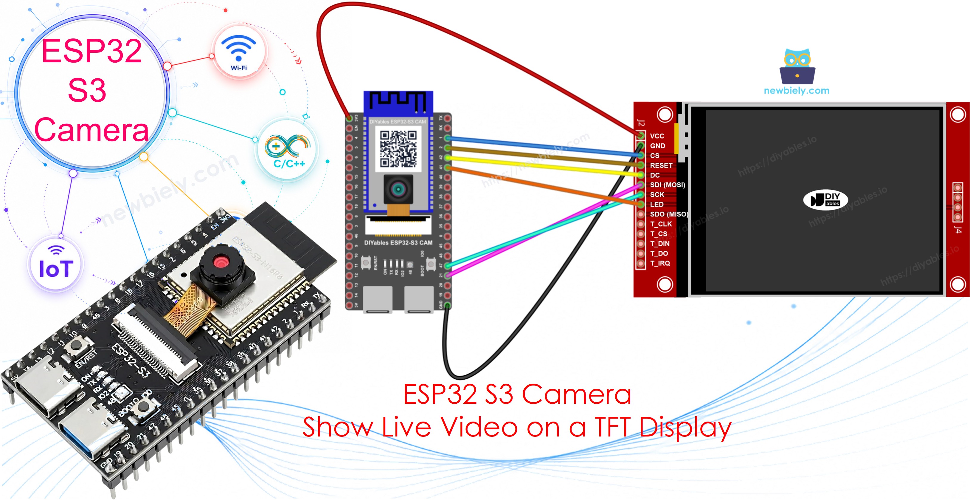
All the other camera projects need WiFi and a web browser. This one needs neither. The ESP32 S3 sends the live picture straight to a TFT display that sits next to it. You get a small camera with its own screen, and it works with no network at all.
What you'll build:
- An ESP32 S3 camera with a TFT display
- A live picture on the screen, with no WiFi and no router
- A frame counter in the Serial Monitor, so you can see how fast it runs
- A small camera you can carry anywhere, with only a power bank
Hardware Preparation
Or you can buy the following kits:
| 1 | × | DIYables Sensor Kit (18 sensors/displays) |
Additionally, some of these links are for products from our own brand, DIYables .
※ NOTE THAT:
The ESP32 S3 camera board has 40 pins, but the screw terminal block and the breakout board have 44 pins. They still work together. Put the camera board in the center of the 44-pin board, so 2 pins stay free on the left side and 2 pins stay free on the right side.
The screw terminal block lets you connect wires with a screwdriver, with no soldering. The breakout board gives you easy pin headers for a breadboard.
How It Works
A camera picture and a display picture are almost the same thing, if you choose the right settings.
| Setting | Value | Why |
|---|---|---|
| Picture format | RGB565 | The display wants exactly this. Two bytes are one colour. |
| Picture size | QVGA, 320 x 240 | The display in landscape is also 320 x 240 |
| Rotation | 1 (landscape) | Turns the panel from standing up to lying down |
So the code is short. Ask the camera for a picture, then give it to the display:
※ NOTE THAT:
Do not use PIXFORMAT_JPEG for this project. A JPEG is packed, and the display cannot read it. PIXFORMAT_RGB565 gives the raw colours, which is what the screen needs.
Why the Colours May Look Wrong
One colour is two bytes, and the camera and the display do not agree about which byte comes first. If you send the picture without thinking, the sky becomes orange and faces become blue.
The code turns the two bytes around before it draws:
※ NOTE THAT:
If your picture looks strange, change the line #define SWAP_BYTES true to false. One of the two values is right for your display, and it costs nothing to try both.
Which Pins Are Left?
The camera uses 14 pins, so you must choose the display pins with care:
| Used by | Pins |
|---|---|
| Camera | GPIO4, 5, 6, 7, 8, 9, 10, 11, 12, 13, 15, 16, 17, 18 |
| microSD card slot | GPIO38, 39, 40 |
| USB | GPIO19, 20 |
| Serial Monitor | GPIO43, 44 |
| Boot (never use) | GPIO0, 3, 45, 46 |
| Free for the display | GPIO1, 2, 14, 21, 41, 42, 47 (we use 6 of them, GPIO14 stays free) |
There are enough free pins for the display, so everything fits.
Different Pins Than the Normal Display Tutorial
If you have already followed the ESP32 S3 - TFT LCD Touch Display SPI tutorial, two wires move in this project:
| Display Pin | Normal display tutorial | This camera project | Why |
|---|---|---|---|
| CS | GPIO1 | GPIO1 | Same |
| DC / RS | GPIO42 | GPIO42 | Same |
| RST | GPIO2 | GPIO2 | Same |
| SDI / MOSI | GPIO11 | GPIO21 | GPIO11 is a camera data pin |
| SCK | GPIO12 | GPIO47 | GPIO12 is a camera data pin |
| SDO / MISO | GPIO13 | not connected | GPIO13 is the camera pixel clock |
※ NOTE THAT:
GPIO11, GPIO12 and GPIO13 are the normal SPI pins of the ESP32 S3, and that is why the other tutorial uses them. On the camera board those three pins belong to the camera, so we must choose other ones. This is the only difference. The three control wires, CS, DC and RST, stay exactly the same.
Wiring Diagram between TFT Display and ESP32 S3
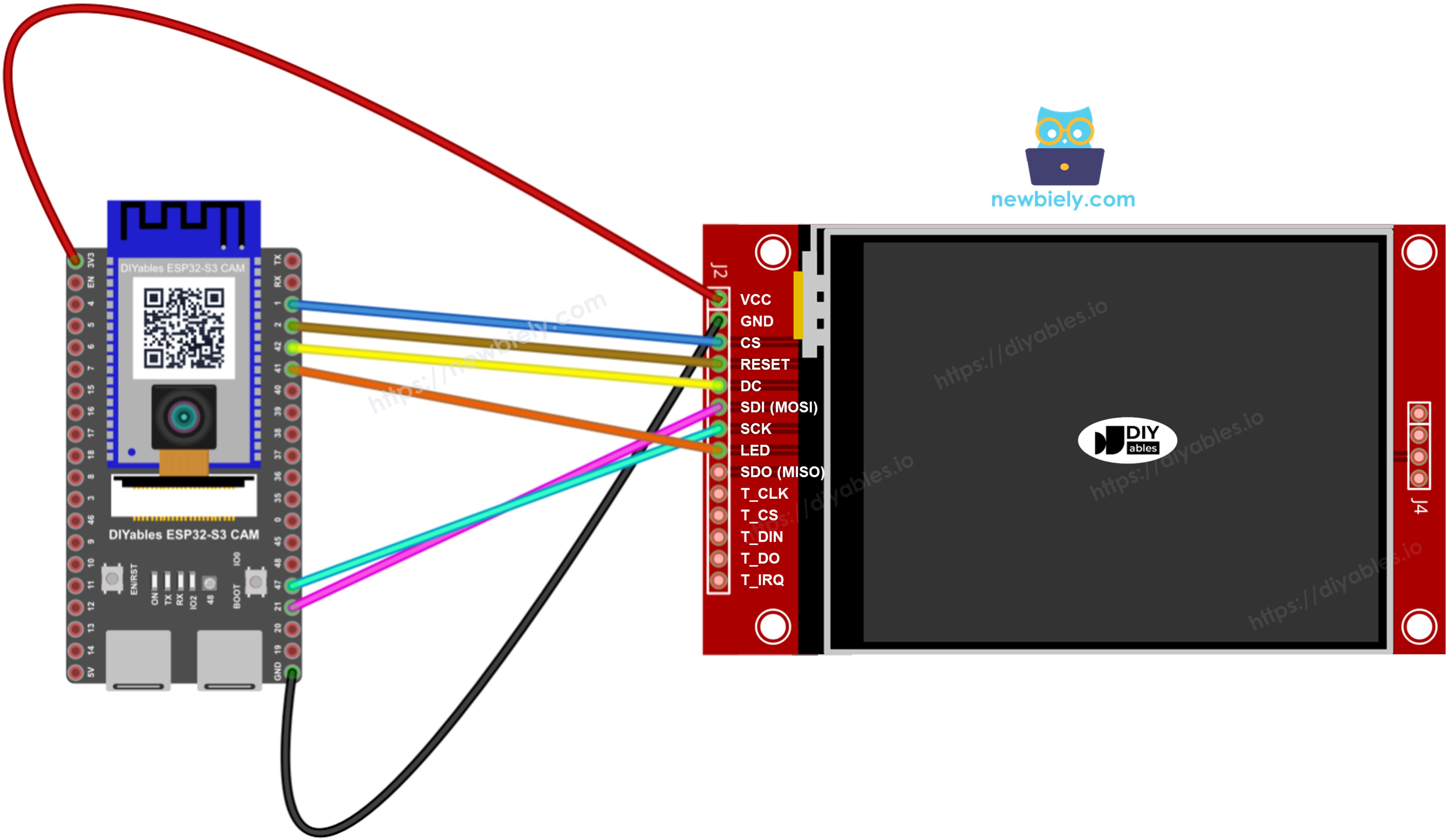
This image is created using Fritzing. Click to enlarge image
| TFT Display Pin | ESP32 S3 Pin | Meaning |
|---|---|---|
| VCC | 3.3V | Power |
| GND | GND | Ground |
| CS | GPIO1 | Chip select |
| DC / RS | GPIO42 | Data or command |
| RESET | GPIO2 | Reset |
| SDI / MOSI | GPIO21 | Data to the display |
| SCK | GPIO47 | Clock |
| LED / BL | GPIO41 | Backlight |
| SDO / MISO | not connected | Only needed to read from the display |
Safety Notes
Use 3.3V for VCC, not 5V. The ESP32 S3 works at 3.3V, and a 5V display can damage the pins of the board.
The LED or BL pin is the backlight. This board has only one 3.3V pin, and the VCC wire already uses it. So we put the backlight on GPIO41 instead, and the code switches it on:
This is easier to wire, and you get two free extras: TFT_display.backlightOff() switches the screen off to save power, and TFT_display.setBacklight(128) makes it half bright.
You do not need the SDO / MISO wire. This project only writes to the display, it never reads from it.
※ NOTE THAT:
Are you also using the microSD card slot? Then keep GPIO38, 39 and 40 free. The display pins above do not touch them, so the card and the display work together.
Install DIYables TFT SPI Library
- Open the Arduino IDE.
- Click the Libraries icon on the left bar.
- Type DIYables TFT SPI into the search box.
- Find the library by DIYables.io and click INSTALL.
- When the IDE asks about other libraries, click INSTALL ALL, because this library uses Adafruit GFX.
- Search for DIYables TFT SPI created by DIYables.io and click the Install button.
The library works with three kinds of display. The code uses the ST7789. Use the line that matches your own module:
| Your display | Line in the code | Size |
|---|---|---|
| ST7789 (used in this tutorial) | DIYables_ST7789_SPI TFT_display(...) | 240 x 320 |
| ILI9341 | DIYables_ILI9341_SPI TFT_display(...) | 240 x 320 |
| ILI9488 | DIYables_ILI9488_SPI TFT_display(...) | 320 x 480 |
For another display, put // in front of the ST7789 line and remove the // from the line of your own display. Nothing else changes.
Arduino IDE Settings for ESP32 S3 Camera
The camera does not work with the default settings of the Arduino IDE. You must change some items in the Tools menu before you upload the code.
| Tools Menu Item | Select This |
|---|---|
| Board | ESP32S3 Dev Module |
| Flash Size | 16MB (128Mb) |
| PSRAM | OPI PSRAM |
| Partition Scheme | Huge APP (3MB No OTA/1MB SPIFFS) |
| CPU Frequency | 240MHz (WiFi) |
| USB Mode | Hardware CDC and JTAG |
| Upload Mode | UART0 / Hardware CDC |
| Upload Speed | 921600 |
| USB CDC On Boot | Enabled |
※ NOTE THAT:
PSRAM is very important here. One RGB565 picture of 320 x 240 takes 153600 bytes, which does not fit in the normal memory of the chip. Without PSRAM the code falls back to a very small picture.
How To Program the Camera Display
- Include the library and choose your display.
※ NOTE THAT:
The ESP32 S3 has more than one SPI bus. We use FSPI, so the display never fights with anything else on the board.
- Tell the SPI bus which pins to use, then start the display. The two -1 mean "we do not read from the display".
- Ask the camera for the picture in the format the display wants.
- Draw the picture. This one line puts the whole camera image on the screen.
- Give the memory back, or the camera stops after a few pictures.
- You can also write text on the screen, because the library uses Adafruit GFX.
ESP32 S3 Code
Detailed Instructions
- New to ESP32 S3? Complete our Getting Started with ESP32 S3 guide first.
- Install the DIYables TFT SPI library, and click INSTALL ALL when the IDE asks.
- Unplug the USB cable, then wire the display as in the table above.
- Copy the above code and paste it into the Arduino IDE.
- If your display is not an ST7789, change the display line. See the table above.
- Change the settings in the Tools menu. See the table above.
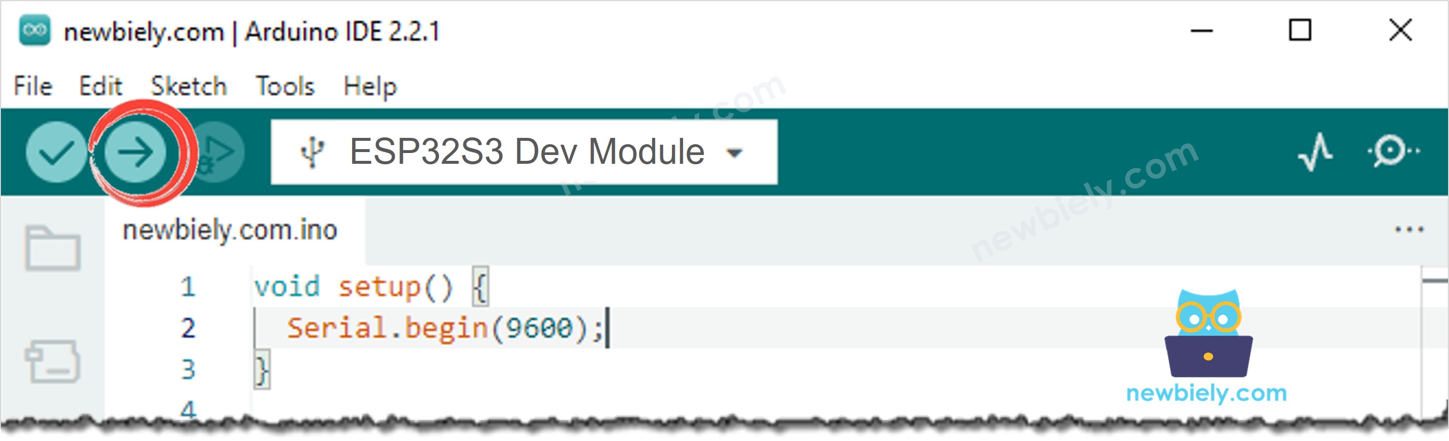
- Compile and upload the code to the ESP32 S3 board by clicking the Upload button in Arduino IDE.
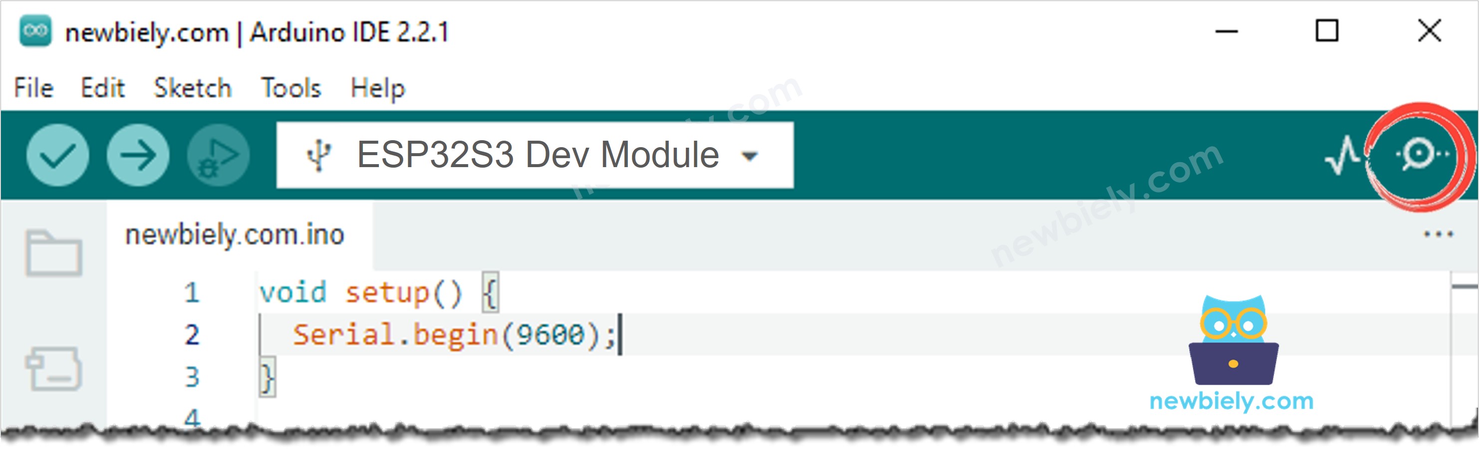
- Open the Serial Monitor in Arduino IDE.
- Press the RESET button one time.
- The screen says Starting camera..., then the live picture appears.
- Pro Tip: Do the colours look wrong? Change #define SWAP_BYTES true to false and upload again.
Serial Monitor
The Serial Monitor tells you how many pictures the board draws. The following readings were captured in 2026:
※ NOTE THAT:
About 12 pictures per second is normal. The slow part is the SPI wire to the display, not the camera. A smaller picture is faster, and a bigger picture is slower.
Troubleshooting
The screen is dark, but I can see a faint picture when I shine a light on it.
The backlight is off. Check the LED / BL wire on GPIO41, and check that initBacklight() is in your code.
The backlight is weak, or the board restarts when the screen lights up.
Your display module takes more current than one ESP32 S3 pin can give. Connect LED / BL to 3.3V together with VCC instead, and delete the initBacklight() line. You then lose the on and off control, but the backlight is always full.
The screen stays white or stays black.
- Check the CS, DC and RESET wires. These three are the ones people swap most often.
- Check the LED / BL wire on GPIO41. Without it the backlight stays off and you see nothing, even when the picture is really there.
- Check that VCC is on 3.3V.
The colours are wrong. The sky is orange, faces are blue.
Change #define SWAP_BYTES true to false and upload again.
The picture is upside down or on its side.
Change TFT_display.setRotation(1) to 0, 2 or 3 until it looks right.
The picture is there but very small in one corner.
Your display is bigger than the picture, for example an ILI9488 of 320 x 480. This is normal. You can move the picture to the middle by changing the first two numbers of drawRGBBitmap(0, 0, ...).
The Serial Monitor shows Camera init failed with error 0x105.
Set PSRAM to OPI PSRAM in the Tools menu, and check the flat cable of the camera.
The video is very slow, only 2 or 3 pictures per second.
- Make sure PSRAM is OPI PSRAM, not Disabled.
- Use short wires. Long jumper wires make SPI slow and unreliable.
- Try FRAMESIZE_QQVGA (160 x 120) to see if the wiring is the problem.
The Serial Monitor shows nothing after the boot messages.
If your USB cable is in the port named UART, set USB CDC On Boot to Disabled. If it is in the port named USB, set it to Enabled.
Applications
A camera with its own screen needs no WiFi, no router and no phone. Here are practical projects you can build with this code:
- Portable camera: A camera and a screen with a power bank, and you can carry it anywhere.
- Digital magnifier: Point it at small text or a circuit board and read it on the screen.
- Inspection camera: Look inside a machine, a pipe or a dark box, and watch on the screen.
- Door viewer: A screen inside the house shows who is at the door outside.
- Reversing camera for a model car: Show the picture of the back on a small screen.
- Microscope helper: Put the camera on a lens and show the picture big.
- Photo booth: Let people see themselves before the photo is taken.
- Robot with a face: Give a robot a screen that shows what it sees.
- Teaching tool: Show students how a camera picture becomes pixels on a screen.
- Camera in a place with no network: A factory, a cellar, or a field where WiFi does not reach.
Video Tutorial
Watch the step-by-step video walkthrough for this ESP32 S3 project below.
Challenges
- Beginner: Write the text "LIVE" in the corner of the screen, on top of the picture.
- Intermediate: Add a button. When you press it, the picture freezes for three seconds, like a photo.
- Advanced: Add the microSD card slot. When you press the button, save the picture as a JPEG file, and show "Saved!" on the screen. Remember to use esp_camera_reconfigure() to change between RGB565 and JPEG.