
ESP32 S3 - IR Slotted Optical Speed Sensor
This guide walks you through using the ESP32 S3 with an IR slotted optical speed sensor to count objects and to measure how fast a motor turns. Whether you're building a small tachometer for a robot wheel or just getting started with sensors, this step-by-step tutorial will get you up and running.
What you'll build in this tutorial:
- What the IR slotted optical speed sensor (photo interrupter) is and how it works
- How to connect the sensor to the ESP32 S3 safely at 3.3V
- A sketch that counts every object that passes through the slot
- A sketch that measures motor speed in RPM using an encoder disc and an interrupt
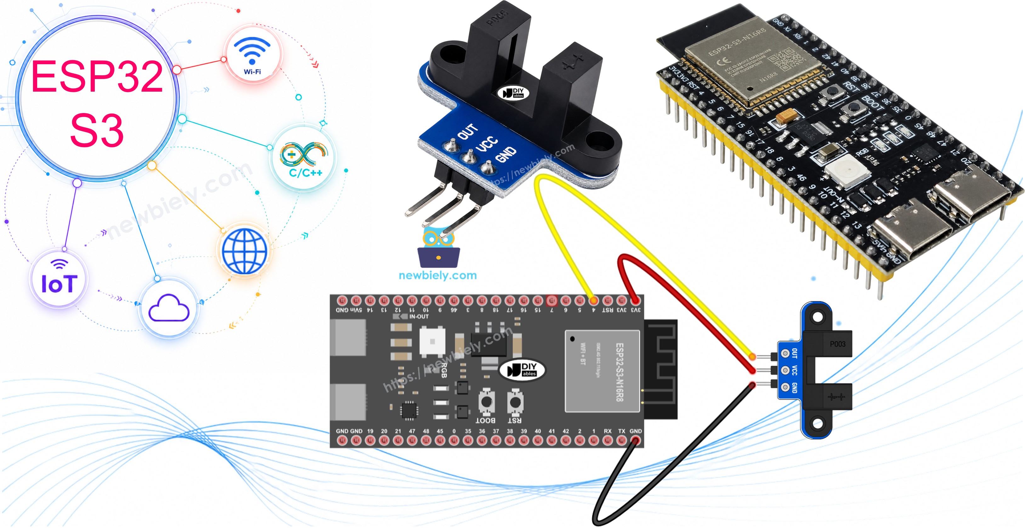
Hardware Preparation
Or you can buy the following kits:
| 1 | × | DIYables ESP32 S3 Starter Kit (ESP32 S3 included) | |
| 1 | × | DIYables Sensor Kit (18 sensors/displays) |
Additionally, some of these links are for products from our own brand, DIYables .
Overview of IR Slotted Optical Speed Sensor
The IR slotted optical speed sensor is a small U-shaped part. Some people call it a photo interrupter, an opto interrupter, or an IR slot sensor. One arm holds an infrared LED. The other arm holds an NPN phototransistor. The two face each other across a narrow gap, and the sensor tells the ESP32 S3 whether something is inside that gap.
Key Specifications
| Item | Value |
|---|---|
| Sensor type | slot-type photoelectric (IR LED + NPN phototransistor) |
| Slot width | 5.9 mm |
| Operating voltage | 3.3V – 5V DC |
| Output | digital (TTL), LOW when blocked, HIGH when clear |
| Signal conditioning | built-in Schmitt trigger |
| Mounting | M3 screw holes at both ends |
| Pins | 3 (VCC, GND, OUT) |
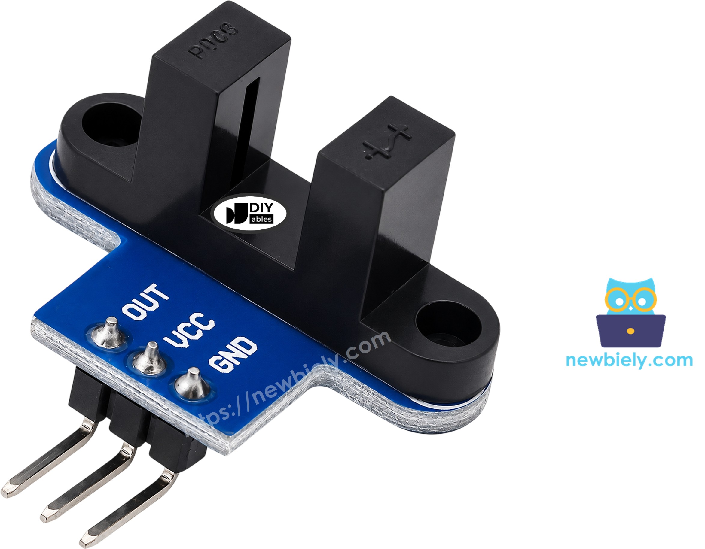
IR Slotted Optical Speed Sensor Pinout
The module has only three pins, so the wiring is short and easy.
- VCC — power input, 3.3V to 5V (use 3.3V on the ESP32 S3)
- GND — ground (0V)
- OUT — digital signal that goes to an ESP32 S3 input pin
※ NOTE THAT:
The pin order can change from one batch to another. Always read the labels printed on your module before you connect the wires.
How the Slotted Optical Sensor Works
Think of the slot as a tiny light gate. When the gap is empty, the infrared light crosses it and reaches the phototransistor, so the OUT pin is HIGH. When an opaque object enters the gap, such as a piece of card or one tooth of an encoder disc, it blocks the light and the OUT pin drops to LOW.
A built-in Schmitt trigger cleans up the signal before it leaves the module. Because of this, the ESP32 S3 gets a sharp 0 or 1 with no jitter, and you do not need any debounce code. One thing to keep in mind: clear plastic or glass may let infrared light pass, so use opaque objects for reliable results.

Modules from some other makers use the opposite logic. If your module reports "blocked" while the slot is empty, simply swap LOW and HIGH in the first sketch. The RPM sketch counts one edge per slot, so it works with either type.
Wiring Diagram
The sensor needs just three jumper wires to the ESP32 S3. Run VCC to the 3.3V pin, GND to any GND pin, and OUT to GPIO4, which both sketches in this guide use.
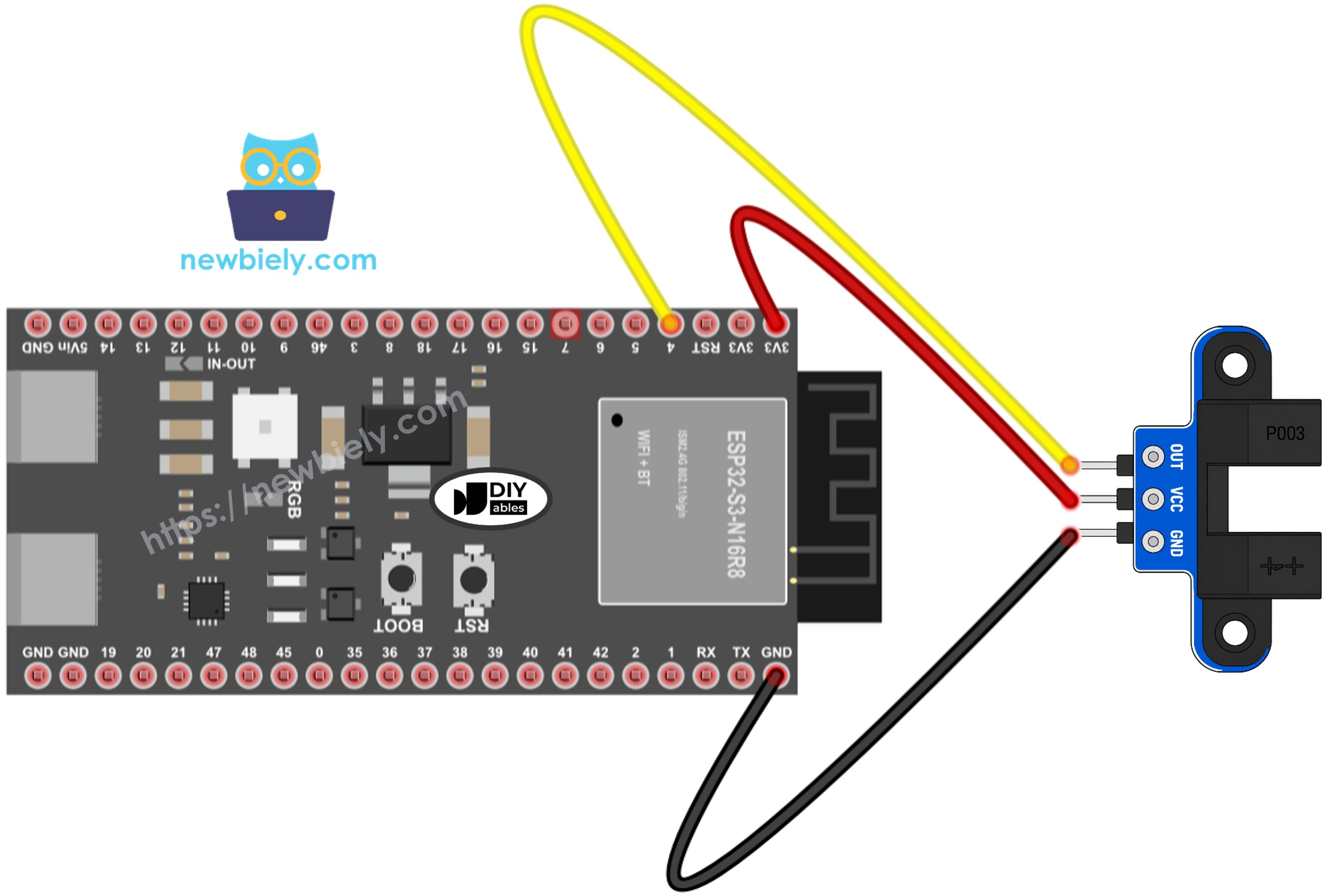
This image is created using Fritzing. Click to enlarge image
| Speed Sensor Pin | ESP32 S3 Pin |
|---|---|
| VCC | 3.3V |
| GND | GND |
| OUT | GPIO4 |
Safety Notes
The OUT pin swings all the way up to whatever voltage you feed into VCC. The ESP32 S3 GPIO pins are made for 3.3V, so power the sensor from the 3.3V pin and not from 5V. This keeps the OUT signal at a level the board can read without harm. Also check the labels on the module once more before you plug in the USB cable, because a swapped VCC and GND can damage the sensor.
How To Program For IR Slotted Optical Speed Sensor
The first sketch uses digitalRead() to check the OUT pin again and again. It remembers the last state and prints a message only when the state changes, and it adds one to a counter each time the slot becomes blocked.
The second sketch is made for speed. Disc teeth pass very fast, so checking the pin inside loop() could miss some of them. Instead, the sketch calls attachInterrupt() on the FALLING edge, which fires once each time a tooth blocks the light. The interrupt function is marked with IRAM_ATTR, as the ESP32 S3 requires, and it only adds one to a volatile counter. Once per second, loop() reads the counter, resets it, and works out the speed.
The speed formula is simple. A standard encoder disc has 20 slots, so one full turn gives 20 pulses. The pulses counted in one second, times 60, gives pulses per minute. Divide that by 20 and you get turns per minute (RPM):
ESP32 S3 Code - Count Objects in the Slot
This sketch watches GPIO4 and prints a line each time the slot is blocked or becomes clear again. Every new block raises the count by one, so you can use it as a simple object counter.
Detailed Instructions
- New to ESP32 S3? Complete our Getting Started with ESP32 S3 guide first.
- Wire the speed sensor to the ESP32 S3 as shown in the wiring diagram.
- Plug the ESP32 S3 into your computer with the USB Type-C cable.
- Open the Arduino IDE and pick ESP32S3 Dev Module under Tools > Board, then choose the right COM port.
- Copy the code above and paste it into a new sketch.
- Click the Upload button to send the code to the board.
- Open the Serial Monitor and set the baud rate to 9600.
- Pass a piece of card or your finger through the slot a few times.
- Watch the messages and the count in the Serial Monitor.
- Pro Tip: Fix the sensor with M3 screws through the holes at each end. A sensor that does not move gives steady counts, even when objects pass quickly.
Serial Monitor Output
ESP32 S3 Code - Measure Motor Speed (RPM)
Now let's turn the sensor into a tachometer. Mount an encoder disc on the motor shaft or wheel so that its teeth pass through the slot without touching the sensor. Each tooth gives one pulse, and the sketch prints the pulse count and the speed once every second.
Detailed Instructions
- New to ESP32 S3? Complete our Getting Started with ESP32 S3 guide first.
- Keep the same wiring as in the first example.
- Fix the encoder disc on the shaft so its teeth pass through the slot.
- Copy the RPM code above into the Arduino IDE and click Upload.
- Open the Serial Monitor at 9600 baud.
- Spin the disc by hand, or power the motor. To drive the motor, see the ESP32 S3 DC motor tutorial.
- Read the pulses and the RPM value that appear every second.
- Pro Tip: If your disc does not have 20 slots, count them and change the SLOTS_PER_TURN value in the code. Otherwise the RPM will be wrong.
Serial Monitor Output
The output below shows a motor spinning at about 300 RPM, then stopping.
If you want to know how far a wheel has traveled, multiply the number of turns by the wheel's circumference (π × diameter).
Application Ideas
The speed sensor gives a clean pulse for every event, so it fits many measuring and counting projects on the ESP32 S3.
- Motor Tachometer: Show the RPM of a DC motor and check how speed changes with load.
- Robot Wheel Feedback: Measure the speed of each wheel so a robot can drive in a straight line.
- Distance Meter: Count wheel turns and convert them to distance traveled.
- Item Counter: Count small parts that drop through the slot on a sorting line.
- Limit and Position Detection: Put a thin flag on a moving part and stop it when the flag enters the slot.
- Fan Speed Monitor: Track how fast a cooling fan spins and warn when it slows down.
For objects that are farther away and do not fit in a slot, the ESP32 S3 obstacle sensor tutorial is a better choice. To read a hand-turned knob with direction, see the ESP32 S3 rotary encoder tutorial.
Challenge Yourself
Try these tasks to build on what you learned in this guide.
- Beginner: Turn on an LED while the slot is blocked and turn it off when the slot is clear.
- Intermediate: Add the distance calculation to the RPM sketch and print the total distance in centimeters.
- Advanced: Use the measured RPM to keep a DC motor at a fixed speed by adjusting its PWM value up or down.