
ESP32 S3 - Light Sensor Triggers Relay
This tutorial shows you how to use the ESP32 S3 together with a light sensor to automatically control a relay based on the ambient light level. By combining analog light measurement with relay switching, you will gain a practical understanding of how to trigger high-power loads in response to real-world sensor data on the ESP32 S3.
What you'll build:
- A circuit connecting a light sensor (photoresistor/LDR) and a relay module to the ESP32 S3
- A sketch that continuously reads the analog value from the light sensor
- A system that automatically turns the relay on when the ambient light drops below a set threshold and turns it off when light returns
- A foundation for building light-triggered automation systems such as automatic night lights, street lamp controllers, and smart greenhouse systems
The LDR light sensor is very affordable, but it requires a resistor for wiring, which can make the setup more complex. To simplify the wiring, you can use an LDR light sensor module as an alternative.
Hardware Preparation
Or you can buy the following kits:
| 1 | × | DIYables ESP32 S3 Starter Kit (ESP32 S3 included) | |
| 1 | × | DIYables Sensor Kit (18 sensors/displays) |
Additionally, some of these links are for products from our own brand, DIYables .
Overview of Relay and Light Sensor
A light sensor (photoresistor) is an analog component whose resistance decreases as ambient light increases, producing a variable voltage that the ESP32 S3 reads through its ADC to determine brightness levels. Paired with a relay, the ESP32 S3 can use that brightness reading to safely switch high-voltage or high-current loads — such as light bulbs, fans, or sirens — that its GPIO pins cannot drive directly.
Key Specifications
We have dedicated tutorials covering each component in depth. Each tutorial contains detailed information and step-by-step instructions about hardware pinout, working principle, wiring connection to the ESP32 S3, and Arduino code. Learn more about them at the following links:
Wiring Diagram
Connect the light sensor and relay to your ESP32 S3 by following the diagram below. Double-check all connections before applying power, especially the high-voltage wiring on the relay's output terminals.
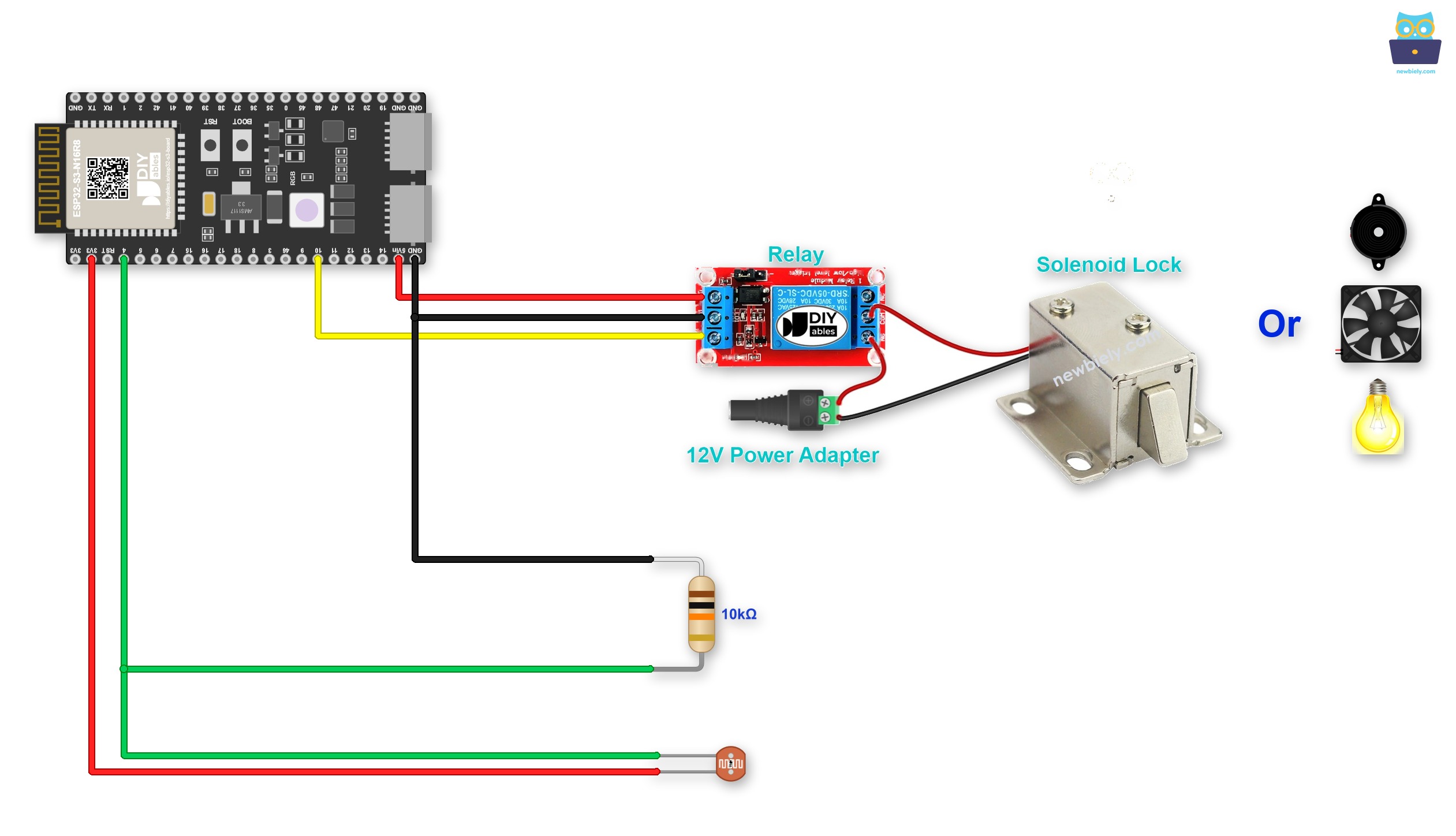
This image is created using Fritzing. Click to enlarge image
Want a stronger connection than jumper wires? Try a Screw Terminal Block for ESP32 S3: the ESP32 S3 sits on it, and each pin gets its own screw terminal. Below is the wiring diagram with the screw terminal board.
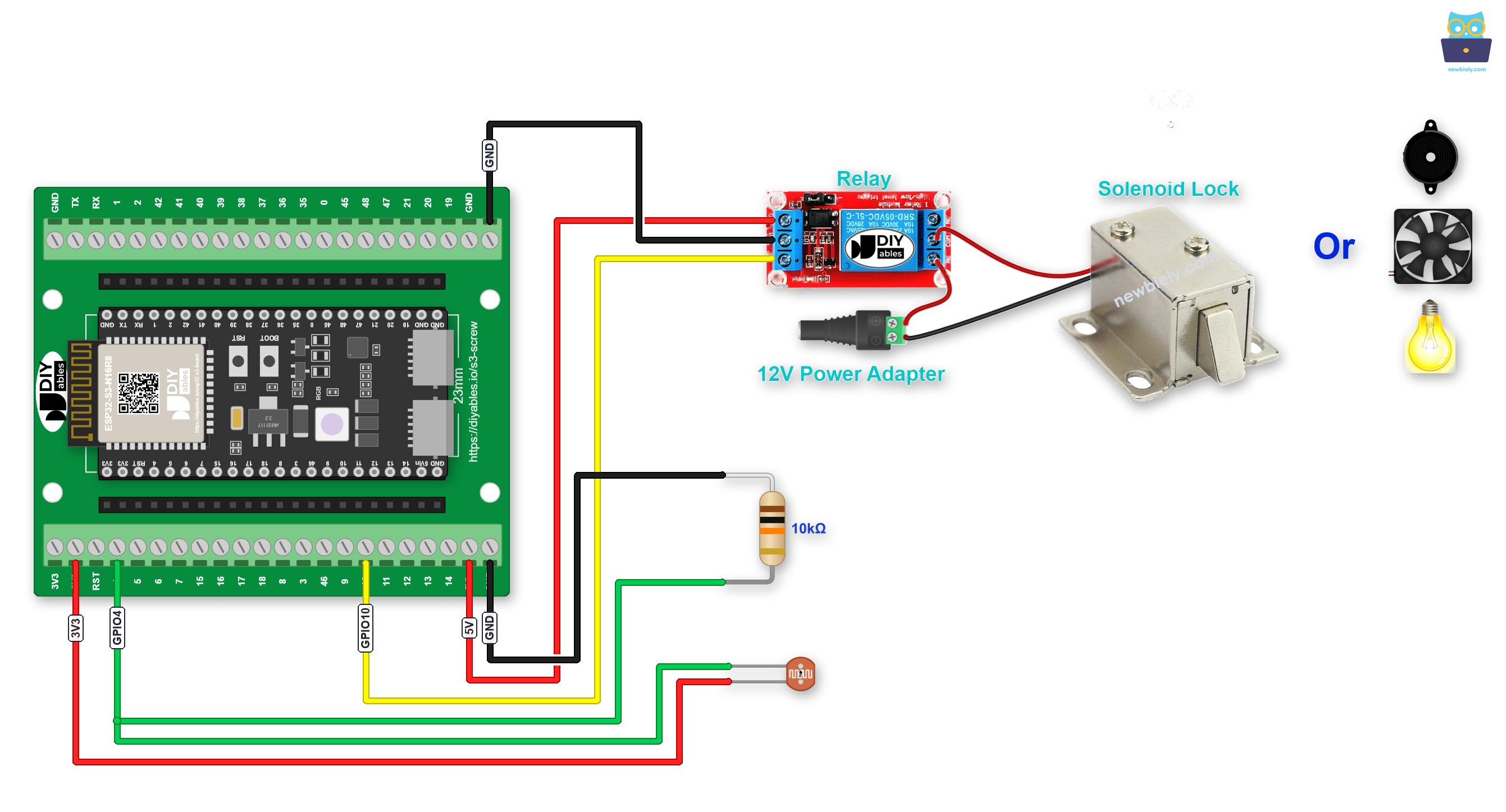
This image is created using Fritzing. Click to enlarge image
You can also use a GPIO Breakout Board for ESP32 S3. It gives each GPIO its own S, 3.3V and GND pins, so module wires plug straight in:
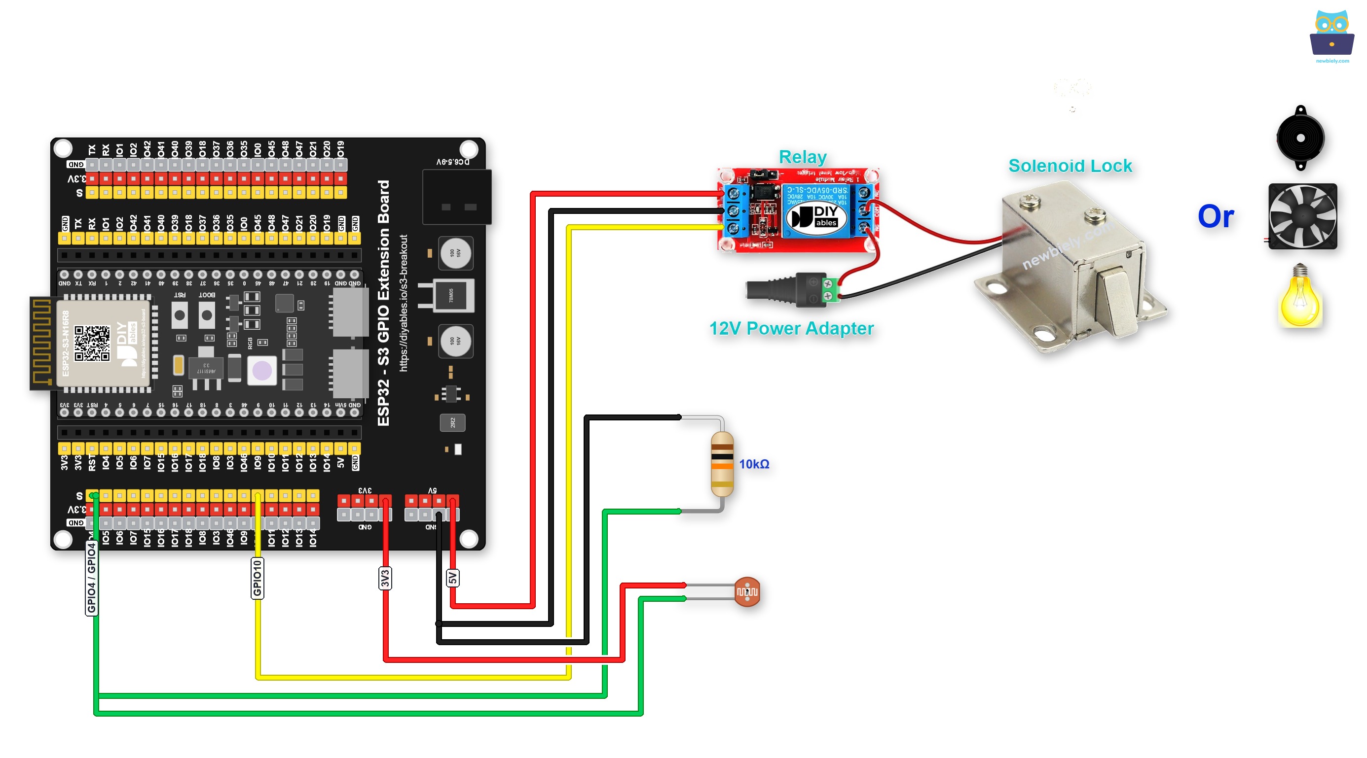
This image is created using Fritzing. Click to enlarge image
Safety Notes
Always verify that the relay's COM and NO (or NC) terminals are securely fastened and that no bare wires are exposed before powering the circuit. Keep the low-voltage control wiring to the ESP32 S3 physically separated from any high-voltage load wiring to reduce the risk of accidental contact.
| Component | Pin | ESP32 S3 Pin |
|---|---|---|
| Light Sensor | Pin 1 | 3.3V |
| Light Sensor | Pin 2 | GPIO4 (Analog Pin) + 10kΩ Resistor |
| 10kΩ Resistor (Other End) | GND | |
| Relay | DC- | GND |
| Relay | DC+ | 5V |
| Relay | IN | GPIO10 |
ESP32 S3 Code
The following code reads the analog value from the light sensor on the ESP32 S3, compares it against a configurable threshold, and switches the relay on when the light level falls below that threshold. The threshold value can be adjusted directly in the code to suit different lighting environments and sensitivity requirements.
Detailed Instructions
- New to ESP32 S3? Complete our Getting Started with ESP32 S3 guide first.
- Wire the components following the wiring diagram shown above.
- Connect the ESP32 S3 board to your PC using a USB Type-C cable.
- Open Arduino IDE on your PC.
- Select the correct ESP32 S3 board and COM port from the Tools menu.
- Copy the above code and paste it into Arduino IDE.
- Click the Upload button to compile and upload the code to the ESP32 S3.
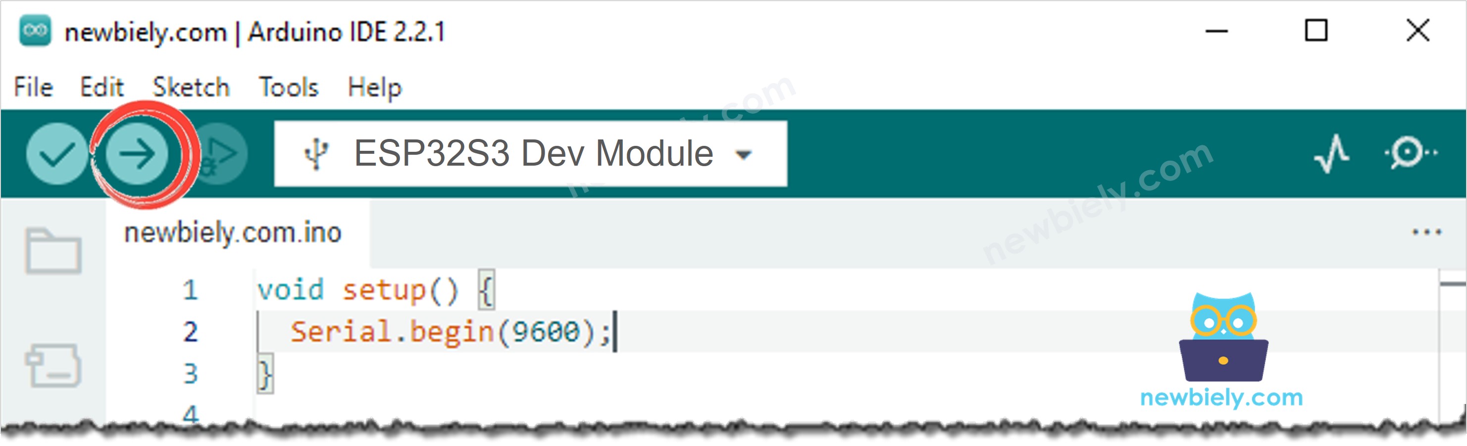
- Open the Serial Monitor at 115200 baud.
- Cover the light sensor with your hand to reduce the light level and observe the relay turning on (you will hear a click).
- Expose the sensor to bright light and observe the relay turning off.
- Check the Serial Monitor to see the live analog values and relay state printed in real time.
- Pro Tip: Try adjusting the threshold value in the code to fine-tune the trigger point — a lower threshold requires near-darkness to activate the relay, while a higher value activates it in dimmer conditions, which is useful for different lighting automation scenarios.
Serial Monitor Output
The following Serial Monitor output shows the ESP32 S3 reading analog values from the light sensor and switching the relay in real time. Each line displays the current ADC reading and the corresponding relay state triggered by the light threshold.
※ NOTE THAT:
This tutorial uses the analogRead() function to read values from an ADC (Analog-to-Digital Converter) connected to a light sensor. The ESP32 S3's ADC is suitable for projects that do not require high accuracy. However, for projects needing precise measurements, keep the following in mind:
- The ESP32 S3's ADC is not perfectly accurate and might require calibration for correct results. Each ESP32 S3 board can vary slightly, so calibration is necessary for each individual board.
- Calibration can be challenging, especially for beginners, and might not always yield the exact results you want.
For projects requiring high precision, consider using an external ADC (e.g ADS1115) with the ESP32 S3. If you still want to calibrate the ESP32 S3's ADC, refer to the ESP32 ADC Calibration Driver.
Application and Project Ideas
Once you can trigger a relay from a light sensor reading on the ESP32 S3, you can extend this pattern to a wide range of light-sensitive automation and control projects.
- Automatic night light: Activate a relay-controlled light bulb or LED strip automatically when ambient light drops below a set level at dusk.
- Smart street lamp controller: Use the light sensor to turn street lamps on at sunset and off at sunrise without a manual timer.
- Greenhouse grow light controller: Switch supplemental grow lights on via relay when natural light levels inside the greenhouse fall below the threshold needed for plant growth.
- Security perimeter light: Trigger a 12V warning light or siren via relay whenever an area becomes unexpectedly dark, indicating a possible obstruction or intrusion.
- Energy-saving HVAC control: Combine light detection with a relay-controlled fan to adjust ventilation based on sunlight intensity as a proxy for room temperature.
- Photography darkroom controller: Automatically energise relay-controlled equipment when the darkroom light drops below a safe threshold, protecting light-sensitive materials.
Relay vs MOSFET Module
A relay is not the only way to switch a device. If your device runs on DC power, such as a 12V LED strip, a 12V solenoid lock or a 12V fan, a MOSFET module can do the same job.
| Relay | MOSFET Module | |
|---|---|---|
| What it can do | turn the device on or off | turn the device on or off, and set its power (PWM) |
| Noise when switching | a click every time | no sound |
| How fast it switches | slow, a few milliseconds | very fast |
| Life | the contacts wear out after many switches | nothing moves, so it lasts long |
| Type of power | AC or DC | DC only |
| Device power supply | any voltage the relay is rated for | about 6V or more |
| Isolation from the ESP32 S3 | yes, between coil and contacts | yes, by the PC817 optocoupler |
| Good for | AC devices, or a simple ON/OFF | DC devices, or dimming and speed control |
Both the relay and the MOSFET module turn on when the ESP32 S3 pin is HIGH. The 3.3V level of the ESP32 S3 is plenty, because the LED in the PC817 optocoupler needs only a few milliamps. So for a simple ON/OFF, the code above stays the same. Only the wiring changes. For AC mains devices, always use the relay.
To learn the MOSFET module pinout, wiring, PWM code and safety tips, see the ESP32 S3 - MOSFET Module tutorial.
Video Tutorial
Watch the step-by-step video walkthrough for this ESP32 S3 project below.
Challenge Yourself
Now that you can control a relay with a light sensor on the ESP32 S3, try these progressively challenging extensions to deepen your understanding and build more capable light-triggered automation systems.
- Beginner: Modify the threshold value in the code and observe how it changes the light level at which the relay activates, then print a confirmation message to the Serial Monitor showing which threshold is currently active.
- Beginner: Add an LED indicator wired to a separate GPIO pin that lights up whenever the relay is energised, giving you a low-voltage visual confirmation alongside the audible relay click.
- Intermediate: Implement hysteresis in the threshold logic so the relay turns on at one light level (e.g., ADC value below 1000) but only turns off when brightness rises above a higher level (e.g., ADC value above 1500), preventing rapid relay chatter near the boundary.
- Intermediate: Add an I2C OLED screen to display the live ADC reading and relay state in a formatted readout, removing the dependency on the Serial Monitor for monitoring.
- Advanced: Store a configurable threshold value in ESP32 S3 non-volatile storage (Preferences library) so the setting persists across power cycles without re-uploading code.
- Advanced: Extend the project with WiFi so the relay can be monitored and the light threshold adjusted remotely from a web page served by the ESP32 S3.