
ESP32 S3 - RFID Door Lock System
Learn how to wire an RFID/NFC RC522 module and a relay-controlled electromagnetic or solenoid lock to an ESP32 S3 to build a fully functional RFID door lock system. By storing authorized tag UIDs directly in the firmware, the ESP32 S3 instantly grants or denies access every time a card or tag is tapped on the reader — no network connection required.
What you'll build:
- A circuit connecting the RFID-RC522 module, a relay, and an electromagnetic or solenoid lock to the ESP32 S3
- Firmware that reads the UID from any tapped RFID or NFC tag and compares it to a stored list of authorized UIDs
- A single-key variant that unlocks the door for one authorized tag and denies all others
- A multi-key variant that maps each authorized tag to a named user (for example, manager and secretary)
https://newbiely.com/images/cover/esp32-s3-rfid-door-lock-system.jpg
Hardware Preparation
Or you can buy the following kits:
| 1 | × | DIYables ESP32 S3 Starter Kit (ESP32 S3 included) | |
| 1 | × | DIYables Sensor Kit (18 sensors/displays) |
Additionally, some of these links are for products from our own brand, DIYables .
Overview of RFID/NFC RC522 Module and Electromagnetic Lock
The RFID-RC522 is a low-cost 13.56 MHz reader module based on the MFRC522 chip from NXP Semiconductors. It communicates with the ESP32 S3 over SPI, operates at 3.3 V logic (directly compatible with the ESP32 S3), and can detect ISO 14443A-compatible cards and tags at distances of up to about 5 cm. An electromagnetic or solenoid lock converts an electrical signal from the ESP32 S3 (routed through a relay) into mechanical bolt movement, making it the ideal actuator for a physical access-control system.
Key Specifications
We have dedicated tutorials covering each component in depth, including their pinout, working principle, and wiring to the ESP32 S3. Learn more about them at the following links:
System Components
A door lock system built with the ESP32 S3 consists of two main parts:
- Door Lock System: ESP32 S3, RFID/NFC RC522 reader, relay, and solenoid or electromagnetic lock
- Door Key: RFID/NFC tags (cards, key fobs, or stickers)
https://newbiely.com/images/tutorial/esp32-s3-rfid-door-lock-component.jpg
How RFID/NFC Door Lock Works
The UIDs of authorized tags are predefined in the ESP32 S3 firmware. When a user taps an RFID or NFC tag on the RC522 reader, the ESP32 S3 reads the UID returned by the module and compares it against the stored list. If the UID matches an authorized entry, the ESP32 S3 deactivates the relay to unlock the electromagnetic or solenoid lock; otherwise, access is denied and the lock stays engaged.
Wiring Diagram
Connect the RC522 module, relay, and electromagnetic or solenoid lock to the ESP32 S3 following the diagram below. Keep the SPI wires between the RC522 and the ESP32 S3 short to reduce noise, and always verify the 3.3 V power connection to the RC522 before applying power.
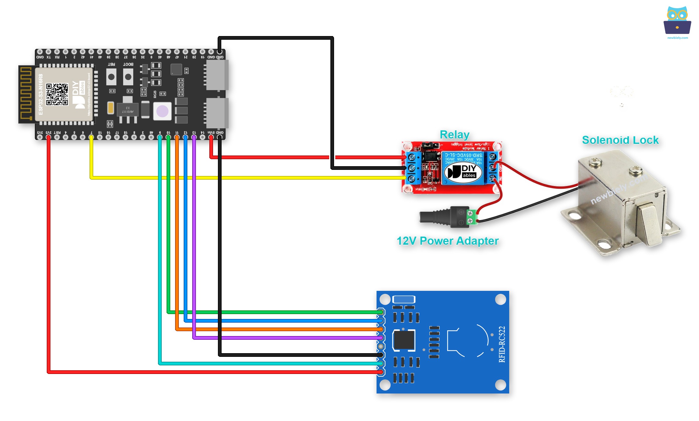
This image is created using Fritzing. Click to enlarge image
If you plan to keep this circuit, think about screw terminals. Simply plug the ESP32 S3 into a Screw Terminal Block for ESP32 S3. Below is the wiring diagram with the screw terminal board.
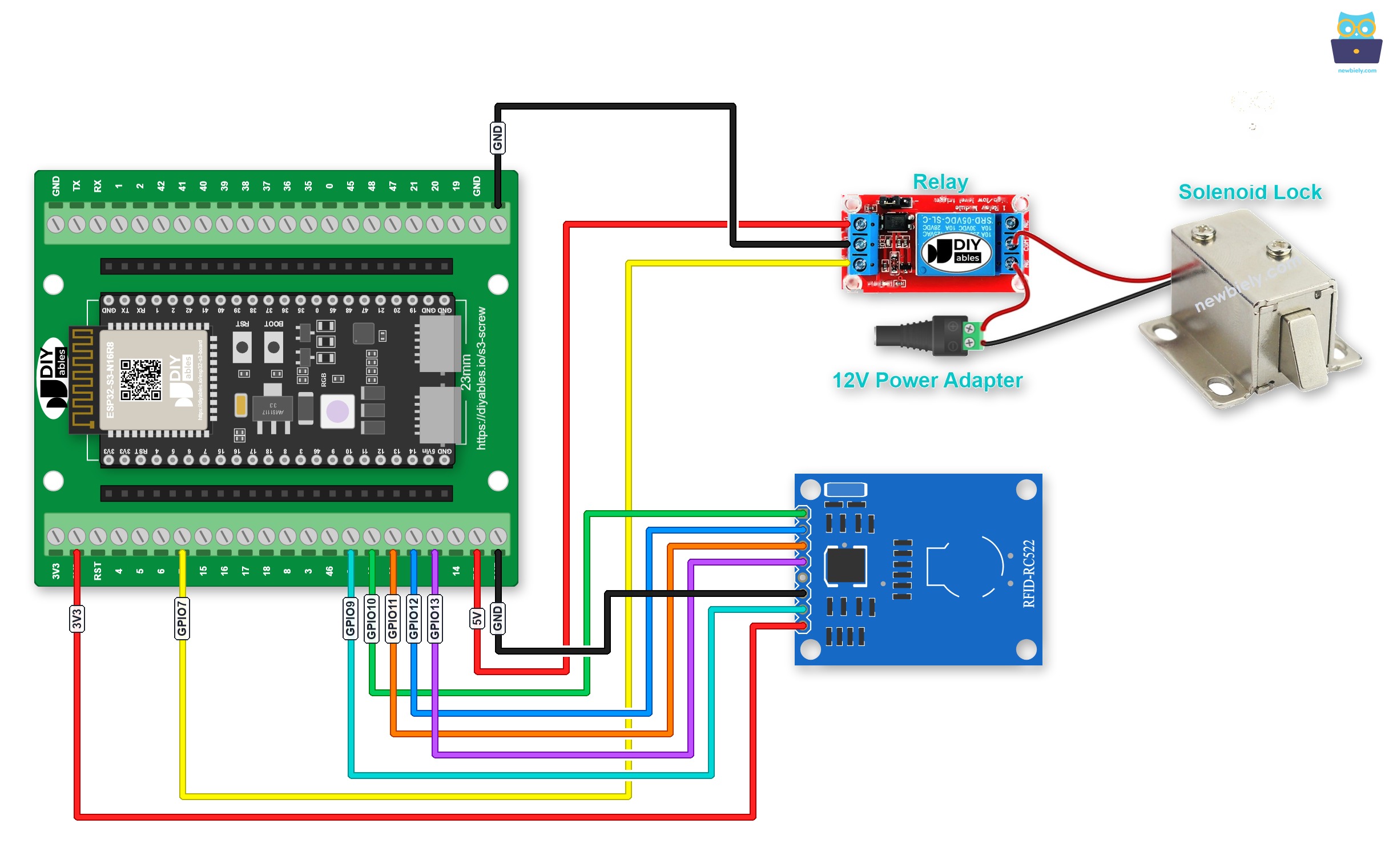
This image is created using Fritzing. Click to enlarge image
A GPIO Breakout Board for ESP32 S3 works too. Besides one S, 3.3V and GND pin for each GPIO, it has extra 3.3V and 5V pins:
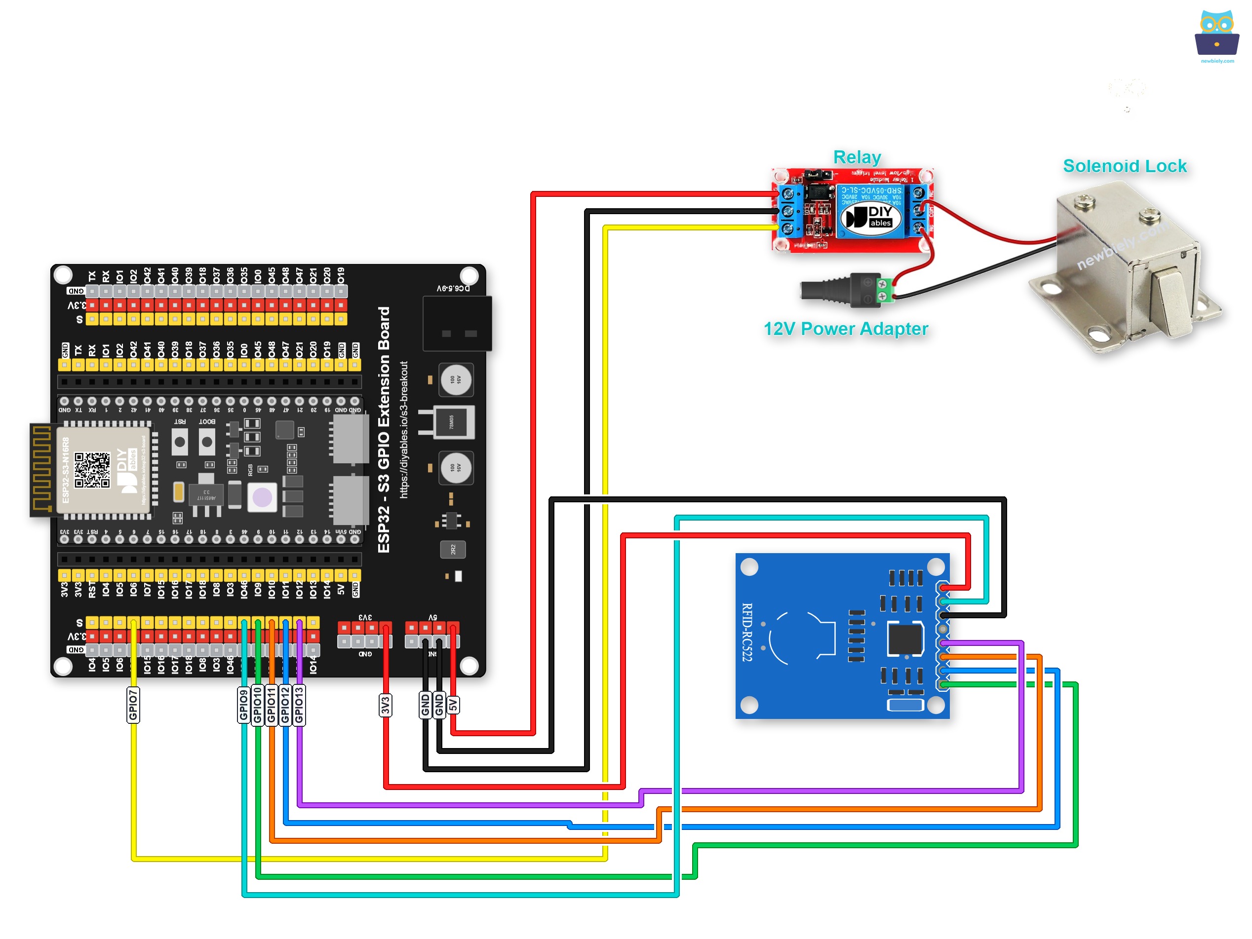
This image is created using Fritzing. Click to enlarge image
Safety Notes
The RFID-RC522 module operates at 3.3 V — connecting its VCC pin to 5 V will permanently damage the module, so double-check the power rail before energising the circuit. The electromagnetic or solenoid lock runs on 12 V DC and must be switched through the relay; never connect it directly to a GPIO pin of the ESP32 S3. Keep the 12 V wiring on the relay's load side physically separated from the low-voltage SPI wiring to avoid noise-induced read errors.
※ NOTE THAT:
The pin order on the RC522 module can vary between manufacturers. Always use the labels printed on the module itself. The image above shows the pinout for modules from the DIYables manufacturer.
| RFID/NFC RC522 Module | ESP32 S3 Pin |
|---|---|
| SS pin | GPIO10 (SS/CS) |
| SCK pin | GPIO12 (SCK) |
| MOSI pin | GPIO11 (MOSI) |
| MISO pin | GPIO13 (MISO) |
| IRQ pin | (not connected) |
| GND pin | GND |
| RST pin | GPIO9 |
| VCC pin | 3.3V |
ESP32 S3 Code - Single Key
The following code initializes the SPI bus and the MFRC522 library, then continuously polls for a new tag. When a tag is detected, its UID is read and compared against the single authorized UID stored in the firmware — if they match, the relay is briefly activated to unlock the door; otherwise, the UID is printed to the Serial Monitor and access is denied.
Detailed Instructions
- New to ESP32 S3? Complete our Getting Started with ESP32 S3 guide first.
- Wire the components following the wiring diagram shown above.
- Connect the ESP32 S3 to your computer using a USB Type-C cable.
- Open Arduino IDE on your computer.
- Select the correct ESP32 S3 board and COM port from the Tools menu.
- Click the Libraries icon on the left bar of Arduino IDE.
- Type "MFRC522" in the search box, then look for the library by GithubCommunity.
- Click Install to install the MFRC522 library.
- Search for MFRC522 created by GithubCommunity and click the Install button.
- Copy the above code and paste it into Arduino IDE.
- Click Upload to compile and upload the code to the ESP32 S3.
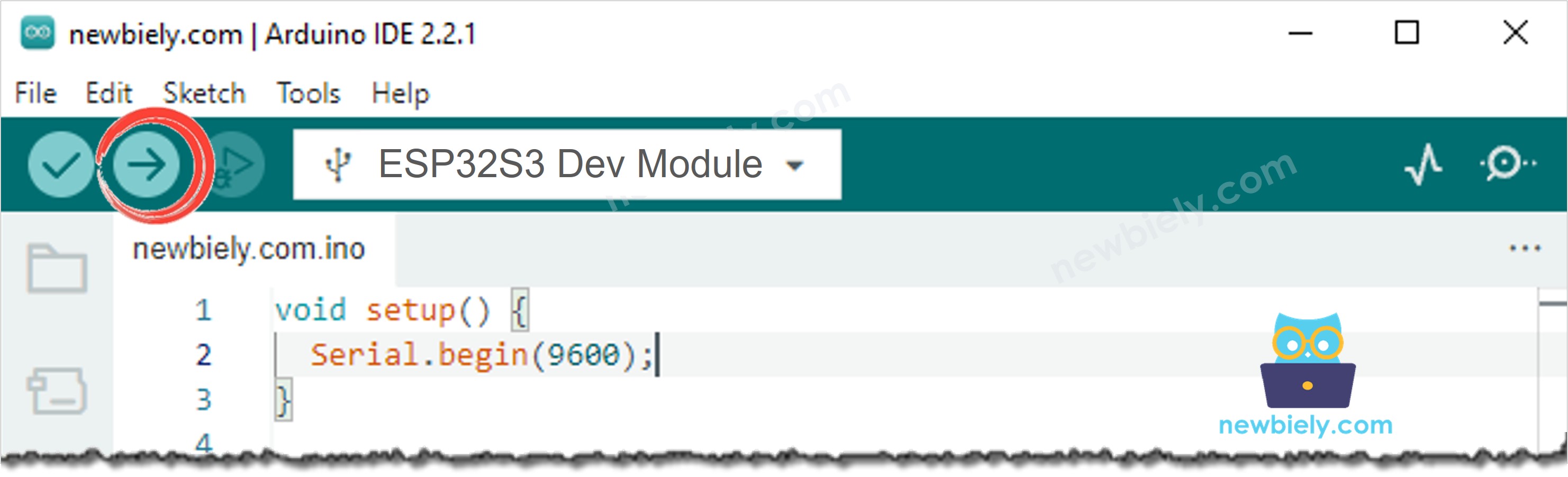
- Open the Serial Monitor in Arduino IDE after uploading.
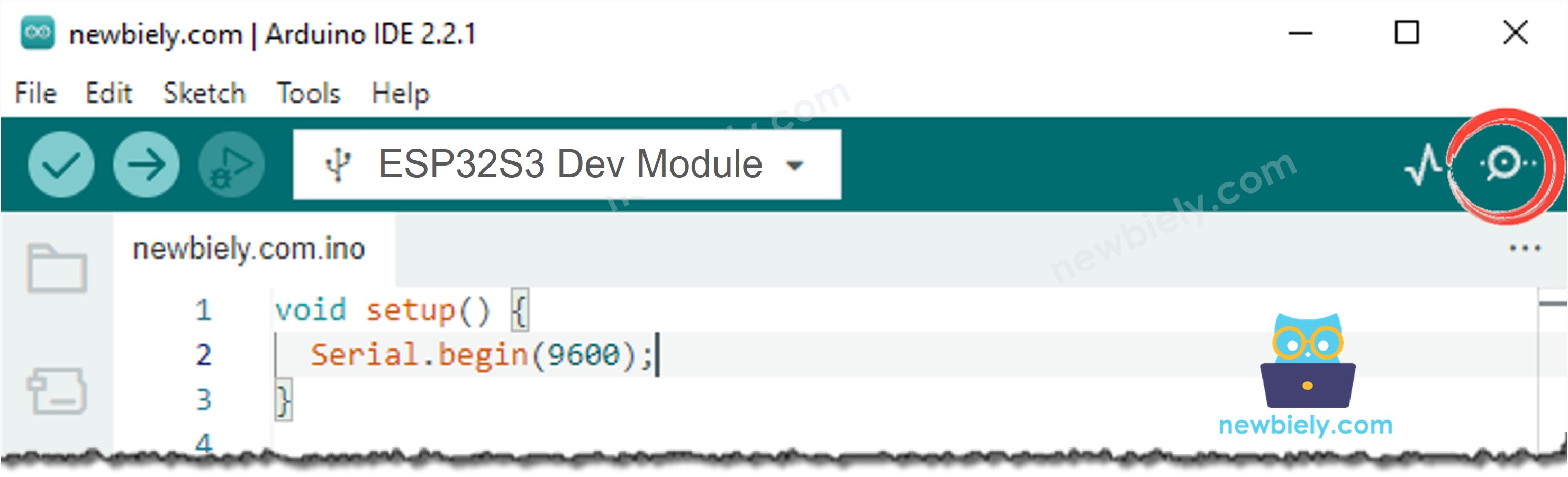
- Tap an RFID or NFC tag that you want to authorize on the RC522 reader and note the UID printed in the Serial Monitor.
- Update the UID on line 18 of the above code. For example, change byte keytagUID[4] = {0xFF, 0xFF, 0xFF, 0xFF}; to byte keytagUID[4] = {0x2B, 0xB8, 0x59, 0xB1};
- Upload the updated code to the ESP32 S3 again.
- Tap the authorized RFID/NFC tag on the RC522 reader and check the Serial Monitor.
- Verify that the electromagnetic or solenoid lock deactivates (unlocks) when access is granted.
- Tap a different (unauthorized) tag and confirm the lock stays engaged.
- Pro Tip: For easier testing the unlock duration is set to 2 seconds in the code — increase this value before deploying the system in a real installation.
ESP32 S3 Code - Multiple Keys
The following code extends the single-key example to support multiple authorized users, each identified by a unique UID and a human-readable name stored in the firmware. When a matching tag is tapped, the ESP32 S3 prints the user's name to the Serial Monitor and unlocks the door; any unrecognized tag is denied and its UID is logged.
Detailed Instructions
- New to ESP32 S3? Complete our Getting Started with ESP32 S3 guide first.
- Follow the same library installation and wiring steps described in the single-key section above.
- Discover the UID of each tag you want to authorize by running the single-key code first (see step 12 above).
- Update the two authorized UIDs in the code with the UIDs of your manager and secretary tags.
- Upload the updated code to the ESP32 S3.
- Tap the manager tag on the RC522 reader, then tap the secretary tag, and observe the Serial Monitor.
- Pro Tip: You can add three, four, or more authorized tags by extending the UID array in the code — each additional entry requires one more UID and one more name string.
※ NOTE THAT:
In this tutorial the authorized UIDs are compiled into the firmware. For a production system you would typically store UIDs in non-volatile memory (such as EEPROM or flash) so they can be added or removed at runtime without reflashing. If you need help implementing that feature, feel free to contact us through our coding service.
Applications and Project Ideas
The ESP32 S3 paired with an RC522 RFID module and a relay-controlled lock opens up a wide range of access-control and security applications that can be deployed with minimal extra hardware. Here are practical ways to put this system to work:
- Office door lock: Assign one RFID card per employee and restrict entry to authorized staff only, with access attempts logged to the Serial Monitor.
- Home smart lock: Replace a traditional key with an RFID card or key fob that only family members carry.
- Server rack security: Protect sensitive IT equipment inside a locked cabinet that only opens for authorized service technicians.
- Locker room system: Give each locker its own RFID-controlled solenoid bolt driven by a dedicated ESP32 S3 for stand-alone operation.
- Shared tutorial access: Grant RFID access to registered members and automatically log every entry for audit purposes.
- Prototype security lab: Build a test rig that logs every access attempt with a timestamp to an SD card or cloud database.
- Parking gate controller: Replace key-card readers at parking barriers with an RC522 and ESP32 S3 to authorize vehicles by their windshield RFID stickers.
Video Tutorial
Watch the step-by-step video walkthrough for this ESP32 S3 project below.
Challenge Yourself
Now that your ESP32 S3 is successfully controlling a door lock with RFID cards, push the project further with these progressively harder challenges:
- Beginner: Add a green LED that lights up for 2 seconds when access is granted and a red LED that flashes when access is denied.
- Beginner: Connect a passive buzzer and play a short beep on access granted and a longer double-beep on access denied.
- Intermediate: Implement a lockout that disables the RFID reader for 30 seconds after three consecutive unauthorized tag attempts.
- Intermediate: Store authorized UIDs in EEPROM so they persist across power cycles and can be updated without reflashing the ESP32 S3.
- Advanced: Add a web interface over the ESP32 S3's Wi-Fi so an administrator can add or revoke authorized UIDs from a browser without touching the hardware.
- Advanced: Combine the RC522 reader with a keypad so the door only opens when both a valid RFID tag and the correct PIN are presented together.