
ESP32 S3 - Door Sensor - LED
This tutorial shows you how to use the ESP32 S3 together with a magnetic door sensor to control an LED automatically based on door state. By connecting a reed switch to a GPIO input and an LED to a GPIO output, you will gain a practical understanding of how to respond to door open and close events with a visual indicator on the ESP32 S3.
What you'll build:
- A circuit connecting a magnetic door sensor and an LED to the ESP32 S3
- A sketch that continuously reads the door sensor state on the ESP32 S3
- A system that automatically turns the LED on when the door is opened and turns it off when the door is closed
- A foundation for building door-activated alarms, entry indicators, and security projects
Hardware Preparation
Or you can buy the following kits:
| 1 | × | DIYables ESP32 S3 Starter Kit (ESP32 S3 included) | |
| 1 | × | DIYables Sensor Kit (18 sensors/displays) |
Additionally, some of these links are for products from our own brand, DIYables .
Buy Note: Use the LED Module for easier wiring. It includes an integrated resistor.
Overview of LED and Door Sensor
The magnetic door sensor and an LED are an effective pairing for building door-detection projects on the ESP32 S3. The sensor consists of a reed switch and a magnet — when the magnet moves away from the reed switch as a door opens, the switch opens its contacts and the ESP32 S3 reads the resulting HIGH signal on its input pin to switch the LED on via a digital GPIO output.
Key Specifications
We have dedicated tutorials covering each component in depth. Each tutorial contains detailed information and step-by-step instructions about hardware pinout, working principle, wiring connection to the ESP32 S3, and Arduino code. Learn more about them at the following links:
For toggling LED each time the door is closed, see the ESP32 S3 - Door Sensor Toggles LED tutorial.
Wiring Diagram
Connect the door sensor and LED to your ESP32 S3 by following the diagram below. Double-check all connections before applying power, paying particular attention to the LED polarity and the 220 ohm current-limiting resistor placement.
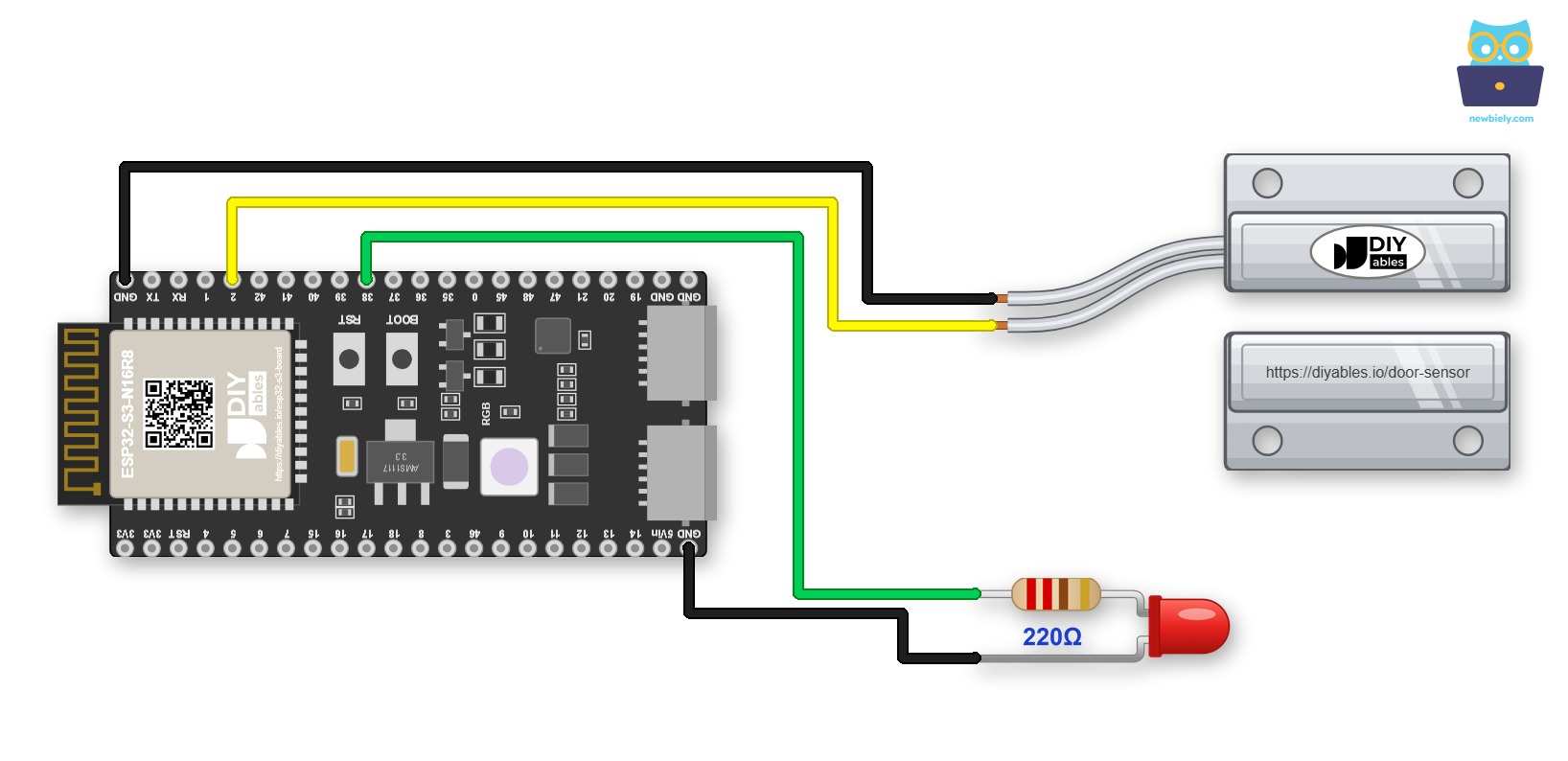
This image is created using Fritzing. Click to enlarge image
Jumper wires can come loose when you move the project. In this case, use a Screw Terminal Block for ESP32 S3. The ESP32 S3 plugs into it, and each pin gets a screw terminal. Below is the wiring diagram with the screw terminal board.
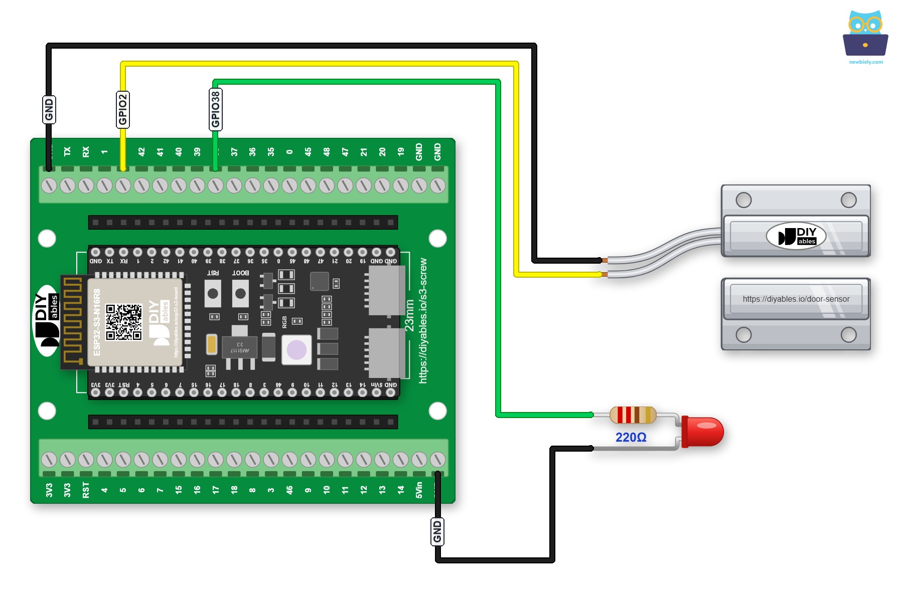
This image is created using Fritzing. Click to enlarge image
Prefer pin headers to screws? Plug the ESP32 S3 into a GPIO Breakout Board for ESP32 S3 instead:
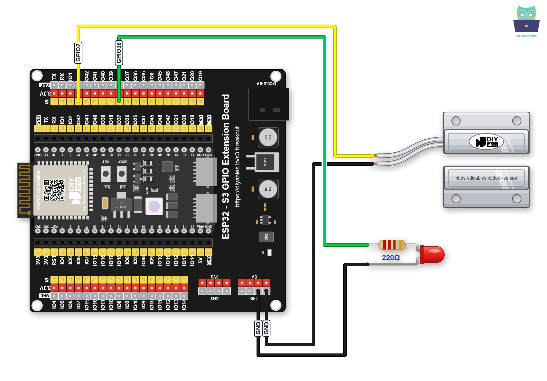
This image is created using Fritzing. Click to enlarge image
Safety Notes
Always include the 220 ohm current-limiting resistor in series with the LED to avoid drawing excessive current through the ESP32 S3 GPIO pin, which can permanently damage the microcontroller. The reed switch is a low-voltage passive device — enable the internal pull-up resistor (INPUT_PULLUP) on the ESP32 S3 input pin to maintain a defined logic level when the switch contacts are open, preventing erratic floating-input readings.
| Door Sensor Pin | ESP32 S3 Pin |
|---|---|
| Wire 1 (reed switch) | GND |
| Wire 2 (reed switch) | GPIO2 |
| LED Anode (+) | GPIO38 (via 220 ohm resistor) |
| LED Cathode (-) | GND |
ESP32 S3 Code
The following code reads the state of the door sensor reed switch on the ESP32 S3 and turns the LED on immediately when the door opens, then turns it off once the door is closed again. Because the ESP32 S3 uses the internal pull-up resistor, the pin reads LOW when the magnet holds the switch closed and HIGH when the door opens and the magnet moves away.
Detailed Instructions
- New to ESP32 S3? Complete our Getting Started with ESP32 S3 guide first.
- Wire the components following the wiring diagram shown above.
- Connect the ESP32 S3 board to your PC using a USB Type-C cable.
- Open Arduino IDE on your PC.
- Select the correct ESP32 S3 board and COM port from the Tools menu.
- Copy the above code and paste it into Arduino IDE.
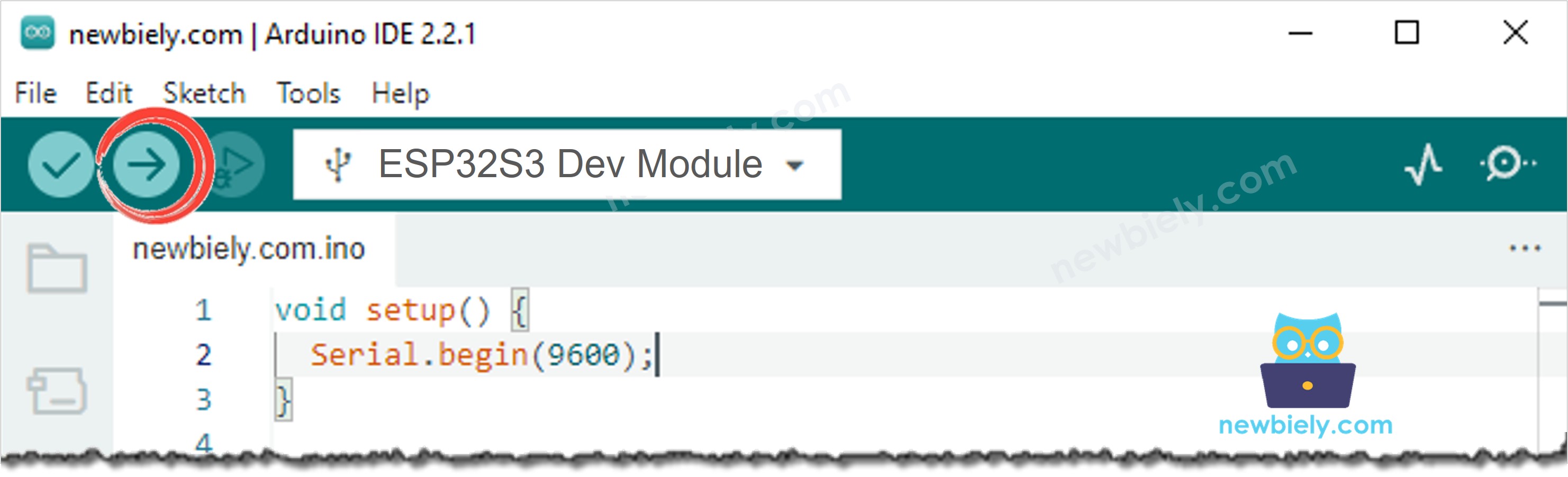
- Click the Upload button to compile and upload the code to the ESP32 S3.
- Move the magnet close to the reed switch to simulate a closed door, then move it away to simulate an open door.
- Observe the LED turn on when the door opens.
- Move the magnet back close to the reed switch and observe the LED turn off when the door closes.
- Check the Serial Monitor to see the live door and LED states printed in real time.
- Pro Tip: Mount the reed switch on the door frame and the magnet on the door itself, ensuring they are aligned and within about 10 mm of each other when the door is closed — correct physical placement is the most common source of unreliable door sensor readings.
Serial Monitor Output
The following Serial Monitor output shows the ESP32 S3 reading door state data from the reed switch sensor in real time. Each line displays the current door state and the corresponding LED state triggered by the sensor output.
Application and Project Ideas
Once you can trigger an LED from a door sensor on the ESP32 S3, you can extend this pattern to a wide range of door-activated and entry-detection projects.
- Entry indicator light: Install an LED strip above a doorway that lights up whenever the door is opened, providing a clear visual signal that someone has entered or exited.
- Security alarm system: Replace the LED with a piezo buzzer or relay-connected siren to trigger an audible alarm whenever a door or window is opened unexpectedly.
- Refrigerator door alert: Mount the sensor on a refrigerator door and trigger a warning LED if the door has been left open for more than a configurable number of seconds.
- Access log recorder: Combine the LED indicator with an SD card or Wi-Fi connection to log every door-open event with a timestamp for a simple access audit trail.
- Child safety guard: Alert parents with a visual or audible indicator whenever a prohibited door such as a garage or exterior gate is opened.
- Smart home integration: Use the door open/close signal to trigger other smart home devices — turn on a hallway light when the front door opens and turn it off a set time after the door closes.
Video Tutorial
Watch the step-by-step video walkthrough for this ESP32 S3 project below.
Challenge Yourself
Now that you can control an LED with a door sensor on the ESP32 S3, try these progressively challenging extensions to deepen your understanding and build more capable door-detection systems.
- Beginner: Add a Serial Monitor message that prints a timestamp using millis() each time the door first opens, so you can track how many times the door has been opened during a session.
- Beginner: Add a second LED wired to a different GPIO pin that blinks rapidly while the primary LED stays solid on, giving a distinct visual pattern to indicate the door is currently open.
- Intermediate: Add a push button that allows the user to enable or disable the door LED feature at runtime, with the LED briefly flashing twice to confirm the mode has been toggled.
- Intermediate: Connect an I2C OLED display to the ESP32 S3 and show a live counter of how many times the door has been opened in the current session alongside the current door state.
- Advanced: Send an email or MQTT message to a home automation platform whenever the door sensor is triggered, using the ESP32 S3 Wi-Fi connection to report entry events remotely.
- Advanced: Build a timed door-alert system that turns the LED on immediately when the door opens and triggers a second warning LED if the door remains open for more than a configurable threshold period.