
ESP32 S3 - DRV8833 DC Motor Driver
The DRV8833 is a tiny dual H-bridge that lets the ESP32 S3 spin small DC motors forward, backward, fast or slow, straight from its 3.3V GPIO pins. In this project you start with a single motor, then add a second one and turn the pair into the drive system of a small robot car.
What you'll build in this tutorial:
- An understanding of what the DRV8833 does and how its four input pins set direction and speed
- A single-motor circuit that ramps up, coasts, reverses and brakes on command
- A two-motor circuit that drives forward, backward, and turns left and right
- Serial Monitor messages that tell you which action is running at every moment
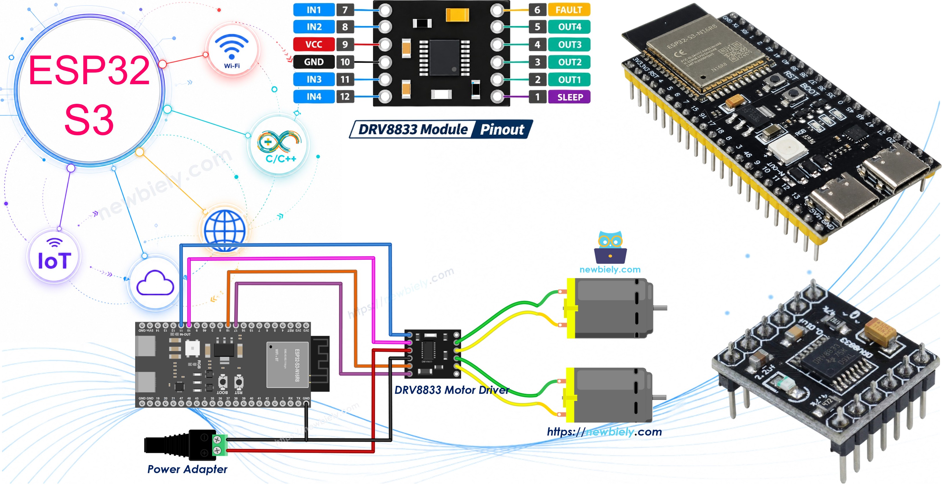
Hardware Preparation
Or you can buy the following kits:
| 1 | × | DIYables ESP32 S3 Starter Kit (ESP32 S3 included) | |
| 1 | × | DIYables Sensor Kit (18 sensors/displays) |
Additionally, some of these links are for products from our own brand, DIYables .
Overview of DRV8833 Motor Driver
A GPIO pin of the ESP32 S3 can only give a few milliamps, but a hobby DC motor wants hundreds. The DRV8833 from Texas Instruments sits in the middle: the ESP32 S3 sends it small logic signals, and the chip switches the motor current from a separate battery or adapter. It has two independent channels, so one module runs two brushed DC motors (or, if you need it later, one bipolar stepper motor). Inside, it uses MOSFET switches with very low resistance, so it wastes much less voltage and makes much less heat than an older L298N. That is a big plus for robots that run on 3 to 9V batteries.
Key Specifications
The motor supply (the VCC pin on the module) accepts 2.7V to 10.8V. There is no separate logic supply pin — the chip makes its own internal logic voltage, so the 3.3V signals from the ESP32 S3 work without a level shifter. Each channel can deliver about 1.5A continuously and 2A peak with good cooling, and the two channels can be joined for about 3A if one bigger motor needs it. PWM frequencies up to 50kHz are supported. Built-in protection covers under-voltage, over-current and over-temperature, and the fault pin goes LOW when any of them trips.
| Feature | Value |
|---|---|
| Motor channels | 2 (A and B) |
| Motor supply voltage (VCC) | 2.7V to 10.8V |
| Logic level | 3.3V or 5V (no logic supply pin needed) |
| Current per channel | about 1.5A RMS, 2A peak |
| Max PWM frequency | 50kHz |
| Protection | Under-voltage, over-current, thermal shutdown |
DRV8833 Pinout
The common red or blue DRV8833 breakout board has the pins below. Labels vary between makers — some boards print AIN1/AIN2/BIN1/BIN2, AOUT1/AOUT2/BOUT1/BOUT2, SLP and FLT instead — but the jobs are the same.
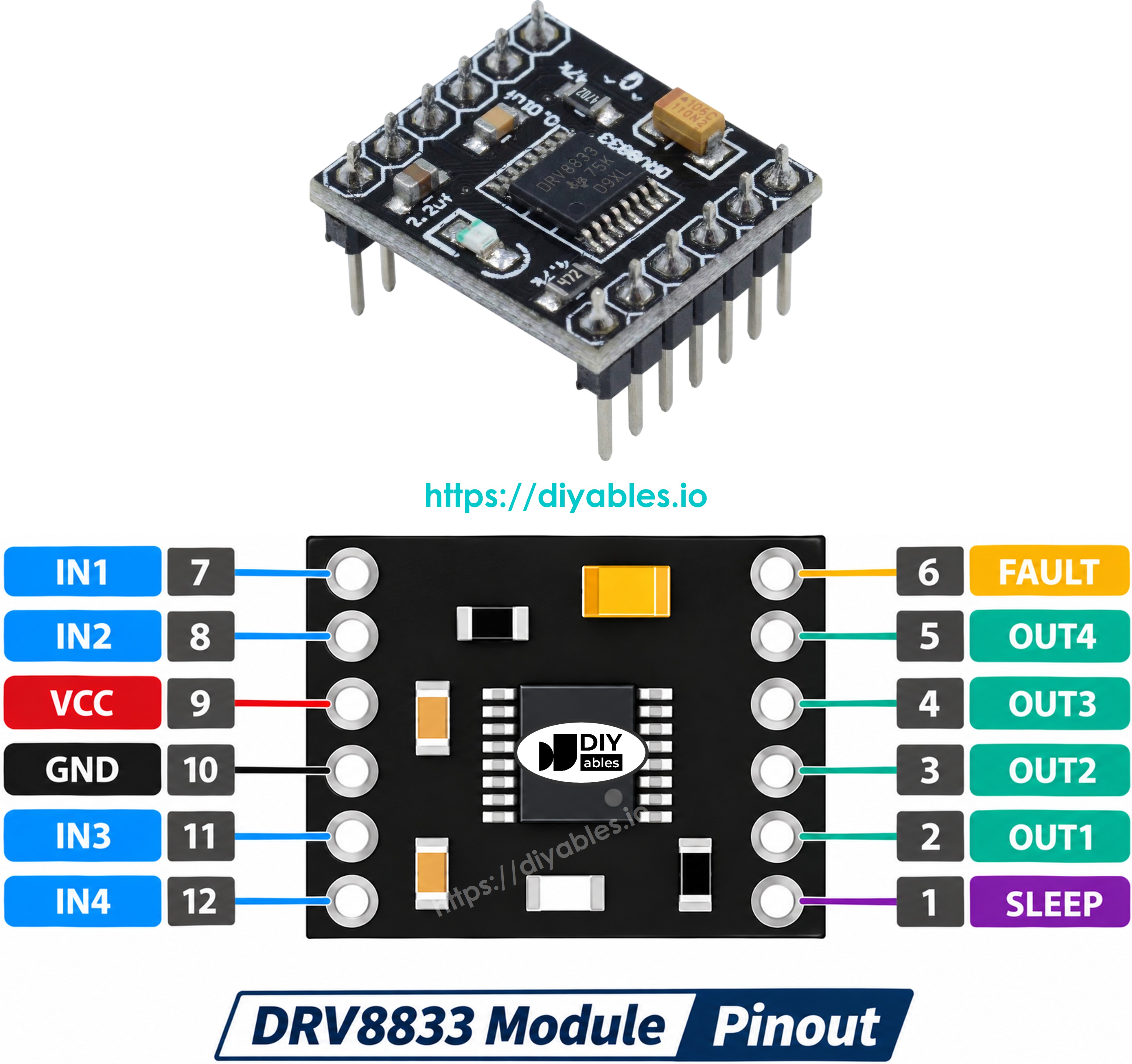
- VCC — motor power input, 2.7V to 10.8V from an external supply
- GND — ground; must be shared with the ESP32 S3 and the motor supply
- IN1 / IN2 — control inputs for motor A, driven by two ESP32 S3 GPIO pins
- IN3 / IN4 — control inputs for motor B, driven by two more GPIO pins
- OUT1 / OUT2 — outputs to the two wires of motor A
- OUT3 / OUT4 — outputs to the two wires of motor B
- EEP (nSLEEP) — enable pin; HIGH turns the driver on, LOW puts it to sleep. Tie it to the ESP32 S3 3.3V pin
- ULT (nFAULT) — open-drain fault output, LOW on a fault; optional, you can leave it unconnected
How the Inputs Control a Motor
Unlike the L298N, the DRV8833 has no ENA/ENB speed pin. Each channel is controlled only by its two input pins, as shown in this truth table (motor A shown; motor B works the same with IN3/IN4):
| IN1 | IN2 | Motor A |
|---|---|---|
| LOW | LOW | Coast (motor free-runs to a stop) |
| HIGH | LOW | Forward |
| LOW | HIGH | Reverse |
| HIGH | HIGH | Brake (fast stop) |
To change speed, the ESP32 S3 sends a PWM signal to one input and holds the other one LOW: PWM on IN1 for forward, PWM on IN2 for reverse. A duty value of 255 is full speed, and smaller values run the motor slower. Because either input may carry PWM, both pins of a channel must be PWM-capable. On the ESP32 S3 this is easy: almost every GPIO can output PWM through analogWrite().
PART 1: Control One DC Motor
Wiring Diagram between DRV8833 and ESP32 S3 - One Motor
Motor A is connected to OUT1 and OUT2, and its two control inputs come from GPIO11 (IN1) and GPIO10 (IN2) of the ESP32 S3. These are free general-purpose pins that support PWM and are not strapping pins. The motor gets its power from a 5V adapter through a DC power jack, and the EEP pin is pulled HIGH by the board's 3.3V pin so the driver stays awake.
Safety Notes
Never feed the motor from the 3.3V or 5V pin of the ESP32 S3; a motor can pull a large current spike at start-up and cause the board to reset or get damaged, so always use a separate supply on the VCC pin of the module. Connect the ground of the adapter, the DRV8833 and the ESP32 S3 together, otherwise the control signals have no common reference and the motor will behave strangely. Keep the supply below 10.8V, and unplug the adapter before you change any wire.
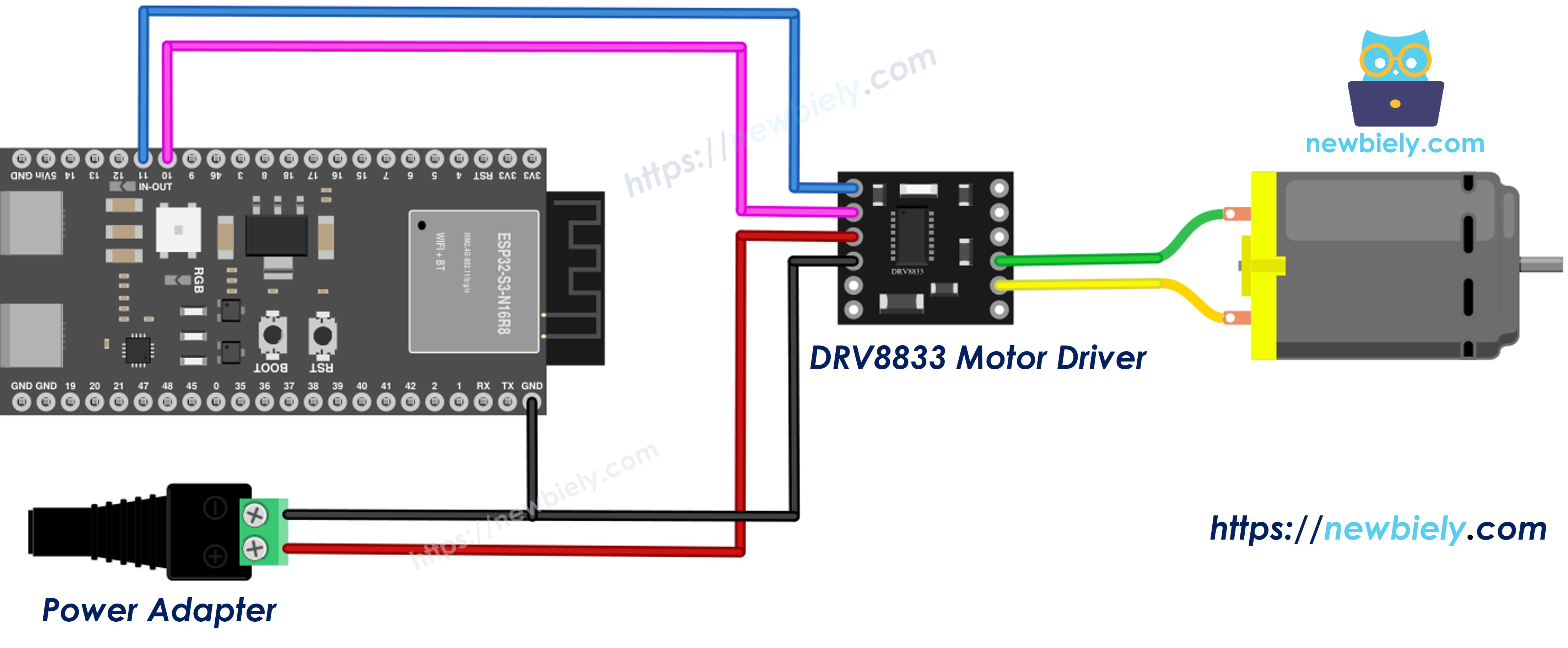
This image is created using Fritzing. Click to enlarge image
| DRV8833 Pin | Connect To |
|---|---|
| IN1 | ESP32 S3 GPIO11 |
| IN2 | ESP32 S3 GPIO10 |
| EEP | ESP32 S3 3.3V |
| GND | ESP32 S3 GND and power supply (-) |
| VCC | 5V power supply (+) |
| OUT1 | DC motor wire 1 |
| OUT2 | DC motor wire 2 |
ESP32 S3 Code - One DC Motor
The sketch wraps the truth table into one helper, motorA(speed), which takes a signed number from -255 to 255: positive values spin the motor forward, negative values spin it in reverse, and 0 lets it coast. A second helper, motorABrake(), sets both inputs HIGH for a quick stop. The main loop ramps the motor up step by step, holds full speed, coasts, runs in reverse at about 70% and finally brakes, printing each stage to the Serial Monitor.
Detailed Instructions
- New to ESP32 S3? Complete our Getting Started with ESP32 S3 guide first.
- Build the circuit: Wire the DRV8833, the motor and the 5V adapter as shown in the one-motor diagram. Leave the adapter unplugged for now.
- Connect the board: Plug the ESP32 S3 into your PC with the USB Type-C cable.
- Prepare Arduino IDE: Open Arduino IDE, then pick the ESP32 S3 board and its COM port.
- Load the sketch: Copy the code above into a new sketch. No extra library is needed.
- Upload: Click the Upload button.
- Power the motor: Plug in the 5V adapter.
- Watch it run: The motor speeds up, holds, coasts, spins in reverse, then brakes.
- Check the messages: Open the Serial Monitor at 115200 baud.
- Pro Tip: If the motor turns the "wrong" way, you don't need to change the code — just swap the two motor wires on OUT1 and OUT2.
Serial Monitor Output
PART 2: Control Two DC Motors
Wiring Diagram between DRV8833 and ESP32 S3 - Two Motors
The second motor goes on OUT3 and OUT4, and its inputs IN3 and IN4 come from GPIO18 and GPIO17. Everything else stays the same as in Part 1, so you only need to add four wires.
Safety Notes
Two motors starting at the same time can draw a lot of current, so choose an adapter or battery pack that can supply at least 1A, and keep it within the 2.7V to 10.8V range. Keep the shared ground in place, and if the DRV8833 chip gets hot to the touch during long runs, give it a short rest or add a small heatsink.
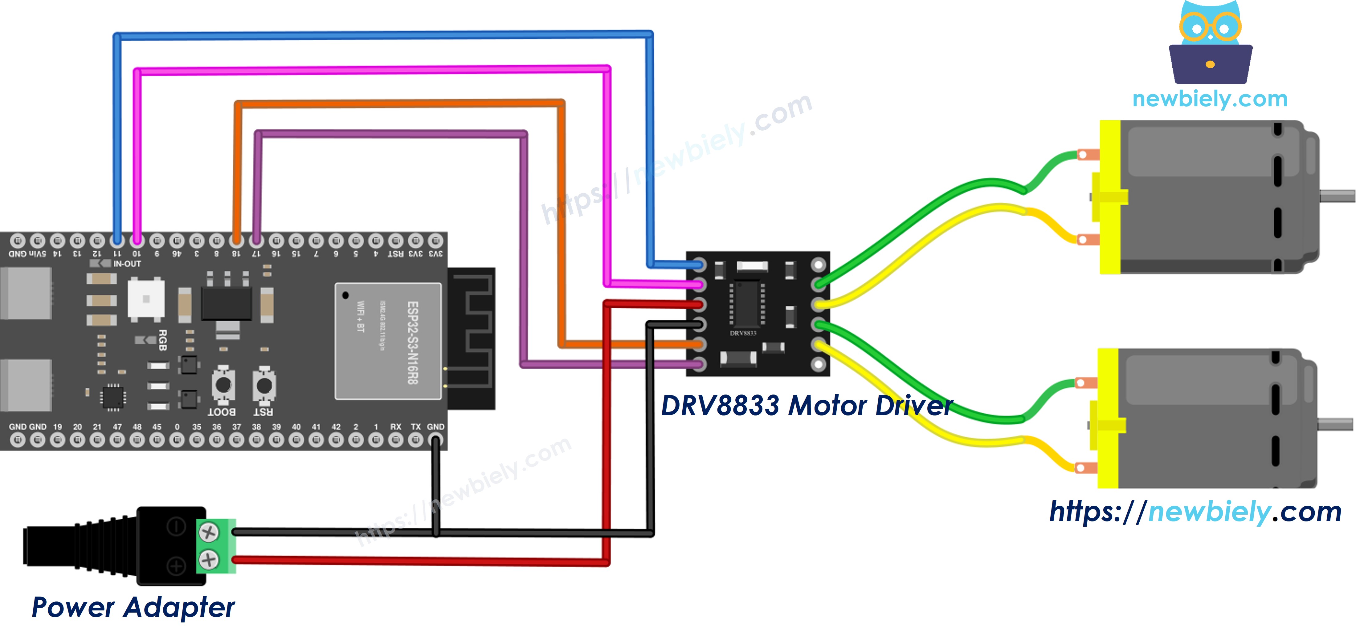
This image is created using Fritzing. Click to enlarge image
| DRV8833 Pin | Connect To |
|---|---|
| IN1 | ESP32 S3 GPIO11 |
| IN2 | ESP32 S3 GPIO10 |
| IN3 | ESP32 S3 GPIO18 |
| IN4 | ESP32 S3 GPIO17 |
| EEP | ESP32 S3 3.3V |
| GND | ESP32 S3 GND and power supply (-) |
| VCC | 5V power supply (+) |
| OUT1, OUT2 | Left DC motor (motor A) |
| OUT3, OUT4 | Right DC motor (motor B) |
ESP32 S3 Code - Two DC Motors
This time, think of the two motors as the left and right wheels of a robot car. A shared function, setChannel(), drives one channel from a signed speed, and the small helpers forward(), backward(), turnLeft(), turnRight() and stopAll() combine both channels into car moves. To turn left, the left wheel runs backward while the right wheel runs forward, so the car spins in place.
Detailed Instructions
- New to ESP32 S3? Complete our Getting Started with ESP32 S3 guide first.
- Add the second motor: Extend the Part 1 circuit by following the two-motor diagram.
- Open the new sketch: Paste the two-motor code into Arduino IDE.
- Upload: Make sure the ESP32 S3 board and COM port are selected, then click Upload.
- Power on: Plug in the motor supply.
- Observe the pattern: Both motors go forward, stop, go backward, stop, then spin in opposite directions to turn left and right.
- Follow along: Open the Serial Monitor at 115200 baud to see each action name.
- Pro Tip: If the car turns right when it should turn left, one motor is wired in reverse — swap that motor's two wires instead of editing the code.
Serial Monitor Output
Applications and Project Ideas
With two motor channels and support for low-voltage batteries, the DRV8833 and ESP32 S3 are a natural base for small moving projects.
- WiFi robot car: Host a web page on the ESP32 S3 with arrow buttons that call the forward, backward and turn functions.
- Line-following robot: Add two IR sensors and steer by slowing one wheel when the line drifts to one side.
- Mini conveyor belt: Move small parts at an adjustable speed and reverse it with a button.
- Motorized blinds: Roll a blind up or down at a slow, quiet speed using one channel.
- Desk fan with speed levels: Set the fan speed from a potentiometer or a touch sensor.
- Camera pan base: Rotate a phone or camera slowly for smooth panorama shots.
Video Tutorial
Watch the step-by-step video walkthrough for this ESP32 S3 project below.
Challenge Yourself
After both motors run well, try these ideas to grow your skills step by step.
- Beginner: Change DRIVE_SPEED and TURN_SPEED and see how slow the motors can go before they stall.
- Beginner: Add a brakeAll() helper that sets all four inputs HIGH and compare its stop with the coast stop.
- Intermediate: Connect the ULT (nFAULT) pin to a GPIO with INPUT_PULLUP and print a warning when it goes LOW.
- Intermediate: Use a joystick module to drive the two motors like a remote-controlled car.
- Advanced: Add an ultrasonic sensor so the car backs up and turns when an obstacle is closer than 20 cm.
- Advanced: Build a web interface on the ESP32 S3 with a speed slider and direction buttons for both motors.