
ESP32 S3 - RFID - Relay
Learn how to connect an RC522 RFID/NFC reader module and a relay to the ESP32 S3 so that only authorized RFID or NFC tags can trigger the relay. This tutorial walks you through everything from wiring the hardware to uploading a finished sketch, giving you a solid foundation for building access-control and automation projects.
What you'll build:
- A circuit connecting the RFID-RC522 module and a relay to the ESP32 S3
- Firmware that reads an RFID/NFC tag UID and compares it against a list of authorized UIDs
- A relay that activates when an authorized tag is detected and stays off for unauthorized tags
- A foundation you can extend into door locks, secure enclosures, and industrial access systems
https://newbiely.com/images/cover/esp32-s3-rfid-relay.jpg
Hardware Preparation
Or you can buy the following kits:
| 1 | × | DIYables ESP32 S3 Starter Kit (ESP32 S3 included) | |
| 1 | × | DIYables Sensor Kit (18 sensors/displays) |
Additionally, some of these links are for products from our own brand, DIYables .
Overview of RFID/NFC RC522 Module and Relay
The RFID-RC522 is a low-cost, 13.56 MHz RFID reader module based on the MFRC522 chip from NXP Semiconductors. It communicates with the ESP32 S3 over SPI and detects ISO 14443A-compatible cards and tags — including the popular MIFARE family — at distances of up to about 5 cm, operating at 3.3 V logic so no level-shifting circuitry is needed. A relay is a magnetically operated switch that lets the ESP32 S3's low-voltage GPIO pins safely control high-voltage or high-current loads, making the two components a natural pair for access-control projects.
Key Specifications
We have dedicated tutorials covering each component in depth. Each tutorial contains detailed information and step-by-step instructions about hardware pinout, working principle, wiring connection to the ESP32 S3, and Arduino code. Learn more about them at the following links:
https://newbiely.com/images/tutorial/esp32-s3-rfid-nfc-relay-component.jpg
How RC522 Module Works
When an RFID/NFC tag is tapped on the RC522 reader, the ESP32 S3 reads the tag's unique identifier (UID) and checks whether that UID appears in a predefined list of authorized UIDs stored in the sketch. If the UID matches an authorized entry, the ESP32 S3 activates the relay; if the UID is not recognized, the relay remains off and the unauthorized UID is printed to the Serial Monitor for diagnostic purposes.
Key Specifications
- Operating frequency: 13.56 MHz
- Communication interface: SPI (default), I2C, UART
- Operating voltage: 3.3 V (do not connect VCC to 5 V)
- Read range: up to ~5 cm (depending on tag and antenna orientation)
- Supported tag types: MIFARE 1KB, MIFARE Ultralight, MIFARE Classic, and other ISO 14443A cards
Wiring Diagram
Connecting the RFID-RC522 module and the relay to the ESP32 S3 requires only jumper wires because the module uses the hardware SPI bus. Keep all wires short to reduce noise on the SPI lines and double-check each connection before powering the board.
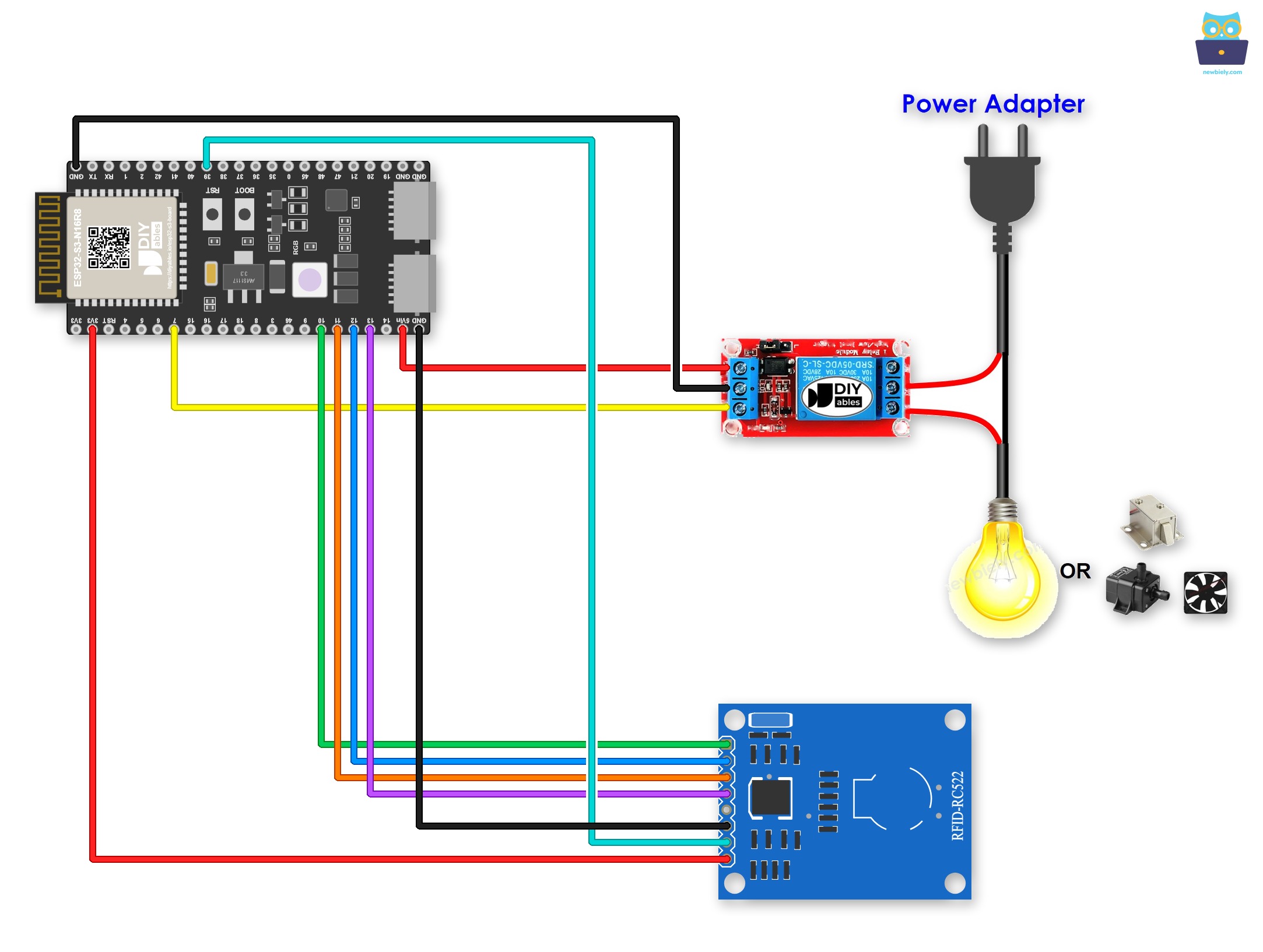
This image is created using Fritzing. Click to enlarge image
A screw terminal keeps each wire tight, even when the board shakes. A Screw Terminal Block for ESP32 S3 solves this. Plug the ESP32 S3 into it and screw the wires in. Below is the wiring diagram with the screw terminal board.
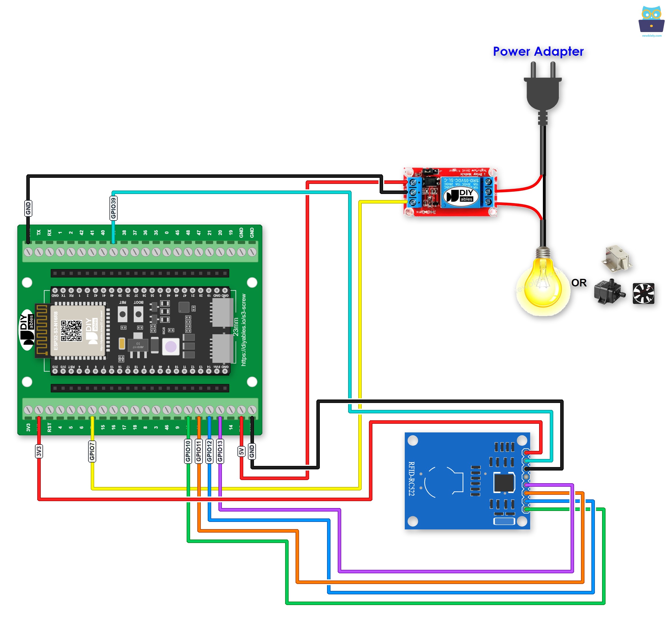
This image is created using Fritzing. Click to enlarge image
A GPIO Breakout Board for ESP32 S3 works too. Besides one S, 3.3V and GND pin for each GPIO, it has extra 3.3V and 5V pins:
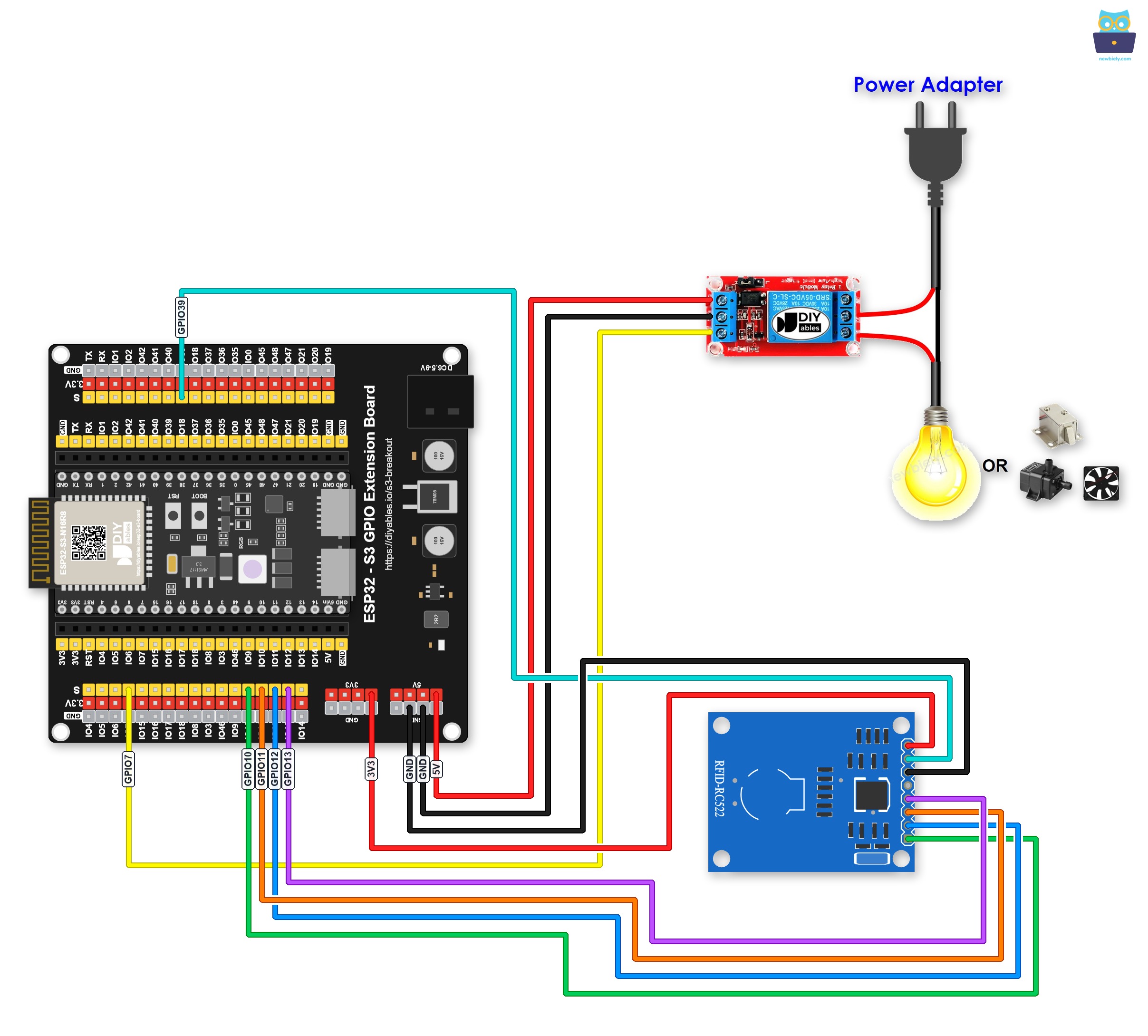
This image is created using Fritzing. Click to enlarge image
Safety Notes
The RFID-RC522 module runs on 3.3 V logic — connecting its VCC pin to the 5 V rail will immediately destroy the module, so always verify your power connection before applying power. The relay module is powered from the 5 V pin on the ESP32 S3 and its control signal comes from a GPIO pin, so keep the high-voltage side of the relay wiring physically separated from the low-voltage control wiring to avoid accidental contact.
| RFID/NFC RC522 Module | ESP32 S3 Pin |
|---|---|
| SS pin | GPIO10 (SS/CS) |
| SCK pin | GPIO12 (SCK) |
| MOSI pin | GPIO11 (MOSI) |
| MISO pin | GPIO13 (MISO) |
| IRQ pin (not connected) | |
| GND pin | GND |
| RST pin | GPIO39 |
| VCC pin | 3.3V |
| Relay | ESP32 S3 Pin |
| DC- | GND |
| DC+ | 5V |
| IN | GPIO7 |
ESP32 S3 Code - Single RFID/NFC Tag
The following code initializes the SPI bus, the MFRC522 library, and the relay pin, then continuously polls for a new RFID or NFC tag. When a tag is detected, the ESP32 S3 reads its UID and compares it against a single predefined authorized UID — activating the relay on a match or printing an "Unauthorized" message if the tag is not recognized.
Detailed Instructions
- New to ESP32 S3? Complete our Getting Started with ESP32 S3 guide first.
- Wire the RFID-RC522 module and relay to the ESP32 S3 following the wiring diagram above.
- Connect the ESP32 S3 to your computer using a USB Type-C cable.
- Open Arduino IDE on your computer.
- Select the correct ESP32 S3 board and COM port from the Tools menu.
- Click the Libraries icon on the left bar of the Arduino IDE.
- Type "MFRC522" in the search box, then look for the library by GithubCommunity.
- Click the Install button to install the MFRC522 library.
- Search for MFRC522 created by GithubCommunity and click the Install button.
- Copy the above code and paste it into Arduino IDE.
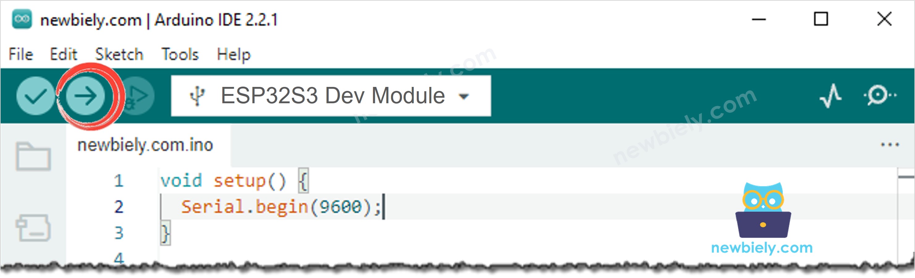
- Click the Upload button to compile and upload the code to the ESP32 S3.
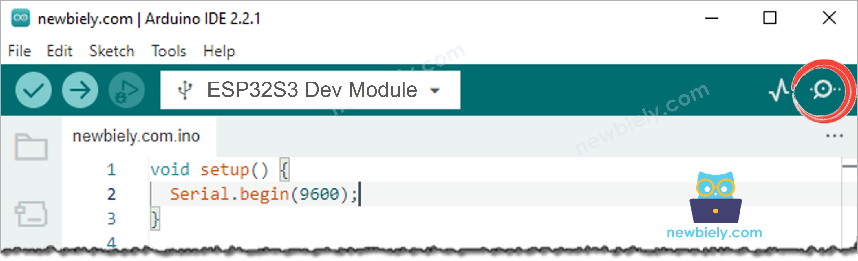
- Open the Serial Monitor in Arduino IDE after uploading.
- Tap an RFID/NFC tag that you want to authorize on the RC522 reader.
- Write down the UID printed in the Serial Monitor.
- Update the UID in the code. For example, change byte authorizedUID[4] = {0xFF, 0xFF, 0xFF, 0xFF}; to byte authorizedUID[4] = {0x2B, 0xB8, 0x59, 0xB1}; using the UID from your tag.
- Upload the code to the ESP32 S3 again.
- Tap the authorized RFID/NFC tag on the RC522 module and observe the relay activating.
- Tap an unauthorized tag and observe the relay remaining off.
- Pro Tip: Hold each tag flat and parallel to the RC522 antenna coil at a distance of 1–3 cm for the most reliable reads.
Serial Monitor Output
Open the Serial Monitor at 9600 baud after uploading the code, then tap RFID or NFC tags onto the RC522 module to see the authorization result printed for each scan.
Serial Monitor Output
Open the Serial Monitor at 9600 baud and tap each authorized tag to verify that all recognized tags activate the relay.
Applications and Project Ideas
The ESP32 S3 paired with an RC522 RFID module and a relay opens up a wide range of access-control and automation applications that can be deployed with minimal extra hardware. Here are practical ways to put this circuit to work:
- Electronic door lock: Activate an electromagnetic or solenoid lock only when an authorized card is tapped, replacing physical keys with RFID credentials.
- Secure equipment access: Restrict power to machinery or tools so that only personnel with authorized RFID badges can operate them.
- Locker system: Build a keyless locker where each student or employee carries a personal RFID card to open their assigned unit.
- Attendance-triggered automation: Combine RFID authorization with a relay to automatically start a workstation, coffee machine, or lighting scene when an employee arrives.
- Time-limited access control: Grant relay activation only during certain hours by combining RFID authentication with an RTC module for scheduled access.
- Visitor management system: Issue temporary RFID tags to guests that activate a relay-controlled gate or turnstile for a defined number of uses.
Video Tutorial
Watch the step-by-step video walkthrough for this ESP32 S3 project below.
Challenge Yourself
Now that your ESP32 S3 can activate a relay with authorized RFID and NFC tags, push the project further with these progressively harder challenges:
- Beginner: Add an LED indicator that turns green when an authorized tag is scanned and red when an unauthorized tag is presented.
- Beginner: Modify the code so the relay stays ON for exactly five seconds after an authorized tag is detected, then turns off automatically.
- Intermediate: Connect a piezo buzzer and play a short success tone for authorized tags and a longer warning tone for unauthorized tags.
- Intermediate: Log every scan — authorized and unauthorized — with a timestamp to a Micro SD Card for a persistent audit trail.
- Advanced: Build a web-based admin panel using the ESP32 S3's Wi-Fi to add and remove authorized UIDs at runtime without re-flashing the firmware.
- Advanced: Combine the RC522 reader with a keypad so the relay activates only when both the correct RFID card and a matching PIN are presented together.