
ESP32 S3 - Ultrasonic Sensor - Relay
This tutorial shows you how to use the ESP32 S3 together with an ultrasonic sensor to automatically control a relay based on the distance to a nearby object. By combining non-contact distance measurement with relay switching, you will gain a practical understanding of how to trigger high-power loads in response to real-world sensor data on the ESP32 S3.
What you'll build:
- A circuit connecting an HC-SR04 ultrasonic sensor and a relay module to the ESP32 S3
- A sketch that continuously measures the distance to an object using the ultrasonic sensor
- A system that automatically turns the relay on when an object comes within a close threshold distance and turns it off when the object moves away
- A foundation for building proximity-triggered automation systems such as automatic doors, security alarms, and obstacle-detection devices
We can extend this tutorial to use the ultrasonic sensor to control an LED strip, siren, light bulb, or motor by connecting them to the relay.
Hardware Preparation
Or you can buy the following kits:
| 1 | × | DIYables ESP32 S3 Starter Kit (ESP32 S3 included) | |
| 1 | × | DIYables Sensor Kit (18 sensors/displays) |
Additionally, some of these links are for products from our own brand, DIYables .
Overview of Relay and Ultrasonic Sensor
The HC-SR04 ultrasonic sensor and a relay are a powerful pairing for building proximity-controlled automation on the ESP32 S3. The sensor emits an ultrasonic pulse and measures the time it takes to reflect off a nearby object, while the ESP32 S3 converts that timing value into a distance reading and uses it to switch a relay that can safely control high-voltage or high-current loads far beyond the capability of the microcontroller's own GPIO pins.
Key Specifications
We have dedicated tutorials covering each component in depth. Each tutorial contains detailed information and step-by-step instructions about hardware pinout, working principle, wiring connection to the ESP32 S3, and Arduino code. Learn more about them at the following links:
Wiring Diagram
Connect the ultrasonic sensor and relay to your ESP32 S3 by following the diagram below. Double-check all connections before applying power, especially the high-voltage wiring on the relay's output terminals.
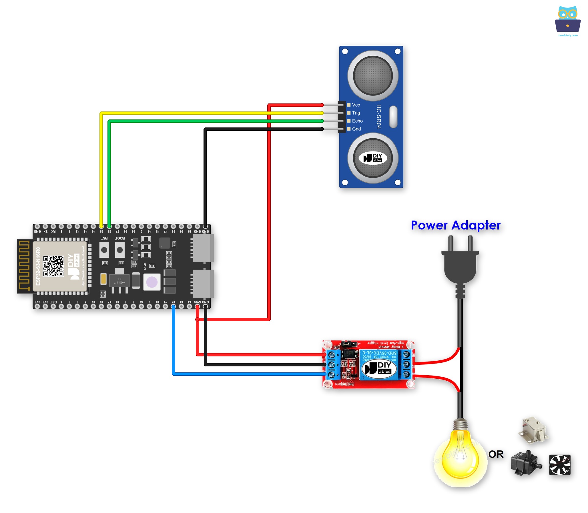
This image is created using Fritzing. Click to enlarge image
A screw terminal keeps each wire tight, even when the board shakes. A Screw Terminal Block for ESP32 S3 solves this. Plug the ESP32 S3 into it and screw the wires in. See the diagram below for the screw terminal version.
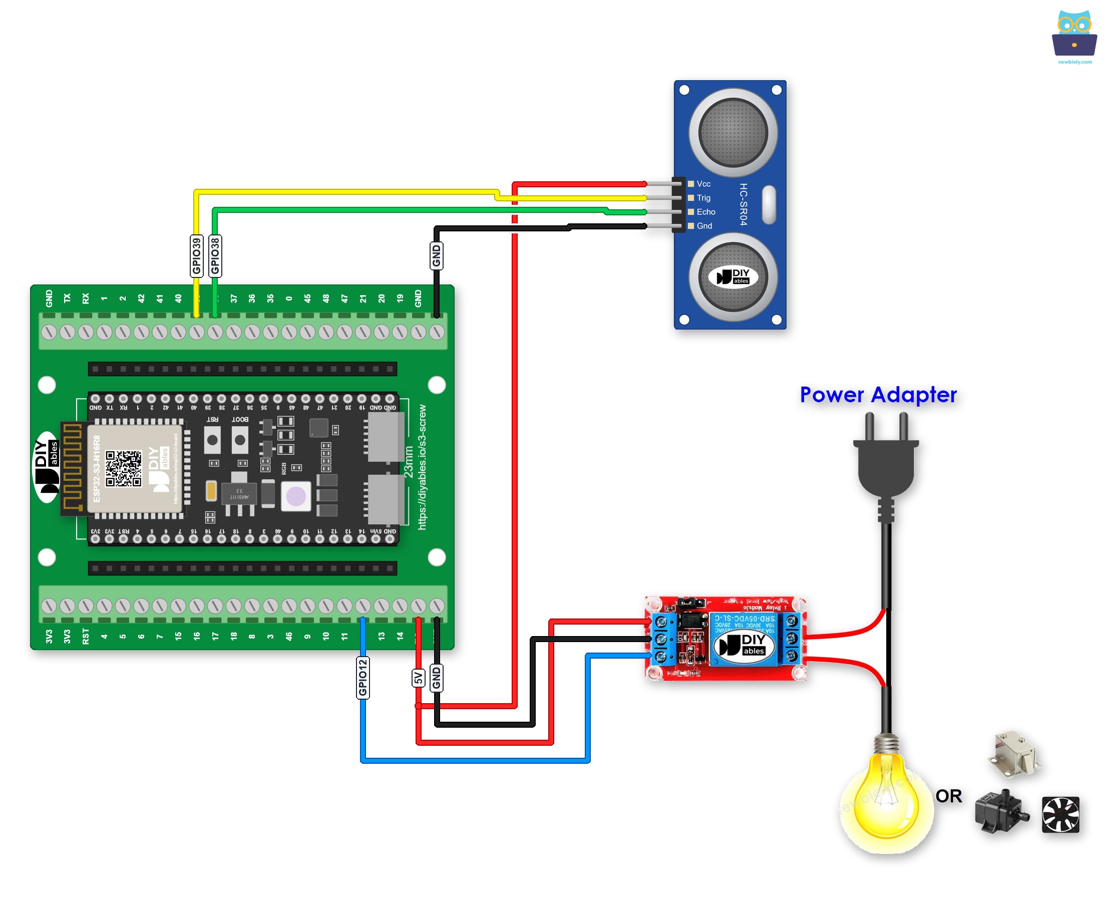
This image is created using Fritzing. Click to enlarge image
A GPIO Breakout Board for ESP32 S3 works too. Besides one S, 3.3V and GND pin for each GPIO, it has extra 3.3V and 5V pins:
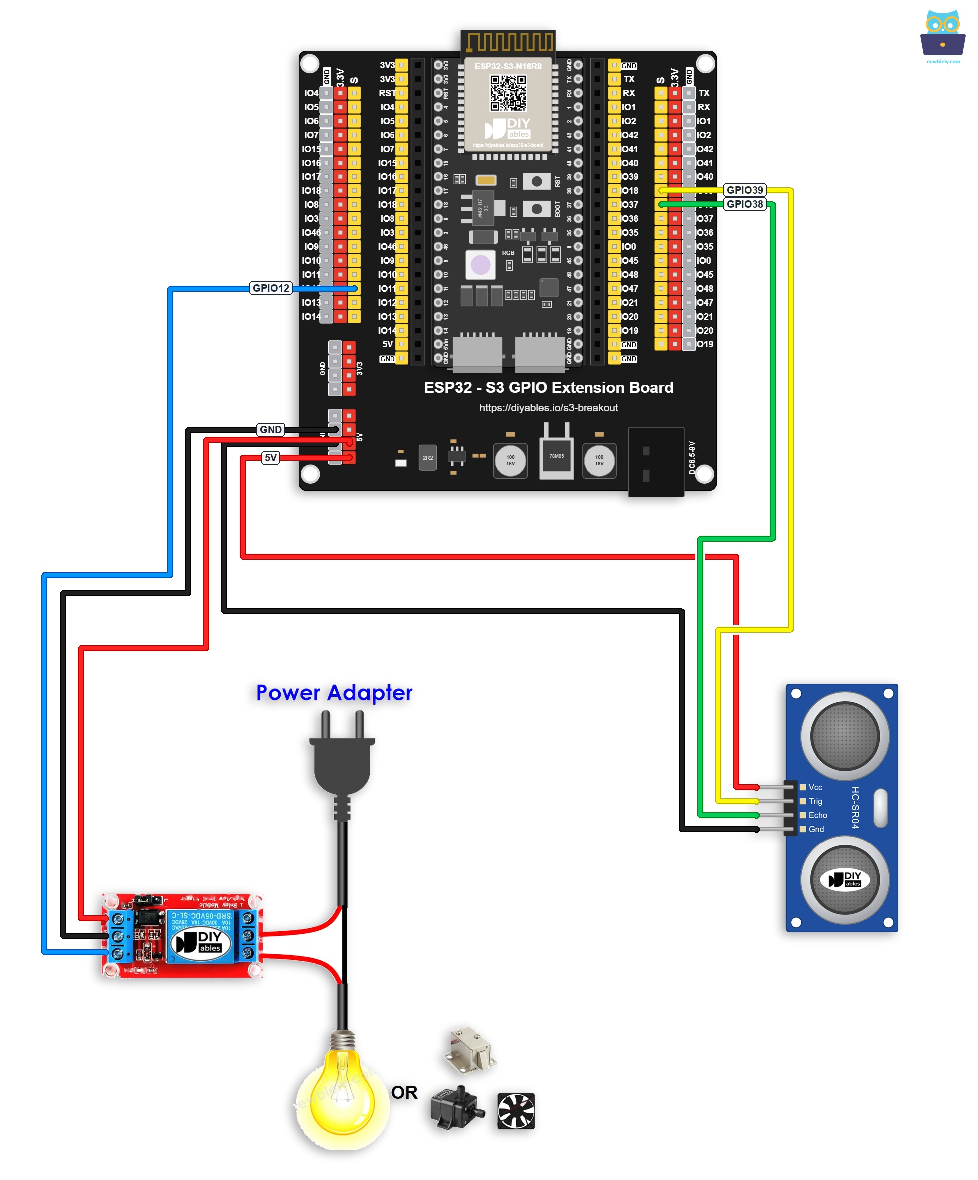
This image is created using Fritzing. Click to enlarge image
Safety Notes
Always verify that the relay's COM and NO (or NC) terminals are securely fastened and that no bare wires are exposed before powering the circuit. Keep the low-voltage control wiring to the ESP32 S3 physically separated from any high-voltage load wiring to reduce the risk of accidental contact.
| Component | Pin | ESP32 S3 Pin |
|---|---|---|
| Ultrasonic Sensor | VCC | 5V |
| Ultrasonic Sensor | GND | GND |
| Ultrasonic Sensor | Trig | GPIO39 |
| Ultrasonic Sensor | Echo | GPIO38 |
| Relay | DC- | GND |
| Relay | DC+ | 5V |
| Relay | IN | GPIO12 |
ESP32 S3 Code
The following code triggers an ultrasonic pulse on the ESP32 S3, measures the round-trip echo time, converts it to a distance in centimetres, and switches the relay on when the measured distance falls below a defined threshold. The threshold value can be adjusted directly in the code to suit different proximity detection requirements.
Detailed Instructions
- New to ESP32 S3? Complete our Getting Started with ESP32 S3 guide first.
- Wire the components following the wiring diagram shown above.
- Connect the ESP32 S3 board to your PC using a USB Type-C cable.
- Open Arduino IDE on your PC.
- Select the correct ESP32 S3 board and COM port from the Tools menu.
- Copy the above code and paste it into Arduino IDE.
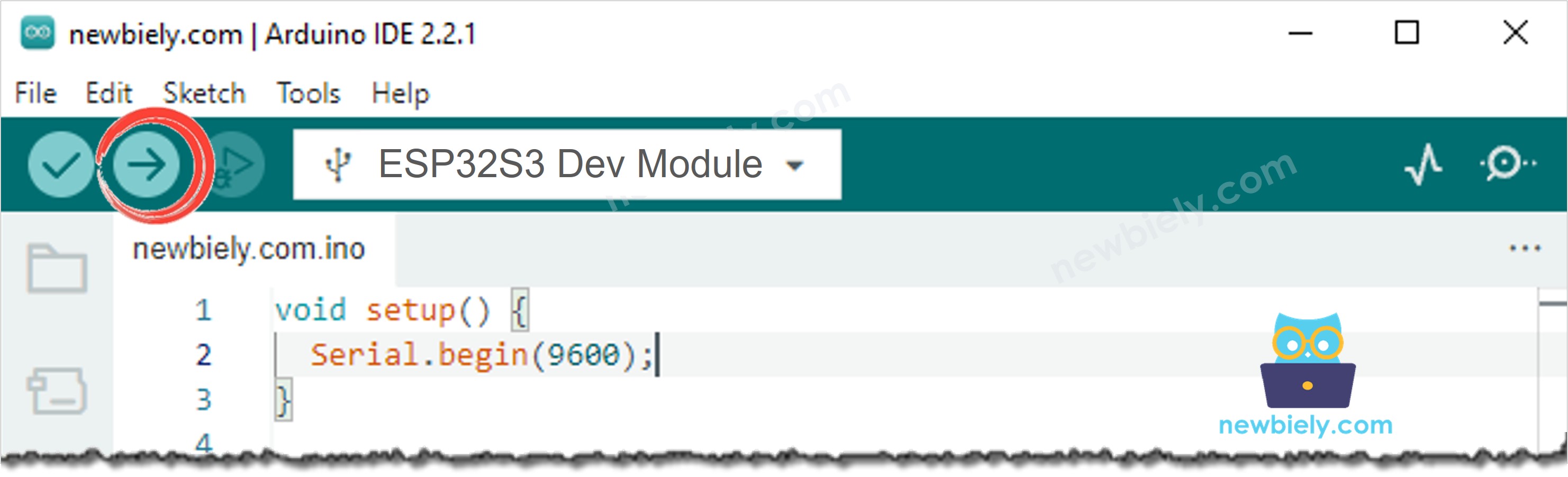
- Click the Upload button to compile and upload the code to the ESP32 S3.
- Open the Serial Monitor at 115200 baud.
- Move your hand toward the ultrasonic sensor and observe the relay turning on (you will hear a click).
- Move your hand away from the sensor and observe the relay turning off.
- Check the Serial Monitor to see the live distance readings and relay state printed in real time.
- Pro Tip: Try adjusting the distance threshold value in the code to fine-tune the detection sensitivity — a lower threshold activates the relay only for very close objects, while a higher value triggers it from further away, which is useful for different automation scenarios.
Serial Monitor Output
The following Serial Monitor output shows the ESP32 S3 reading distance data from the ultrasonic sensor and switching the relay in real time. Each line displays the current measured distance and the corresponding relay state triggered by the proximity threshold.
Application and Project Ideas
Once you can trigger a relay from an ultrasonic distance reading on the ESP32 S3, you can extend this pattern to a wide range of proximity-sensitive automation and control projects.
- Automatic door opener: Mount the sensor near a door and activate a solenoid or motor relay to open the door when a person approaches within a set distance.
- Proximity security alarm: Trigger a 12V siren or warning light via the relay whenever someone enters a restricted zone detected by the sensor.
- Touchless liquid dispenser: Activate a pump relay when a hand is detected within a few centimetres of the sensor nozzle for a fully hands-free dispensing experience.
- Liquid level controller: Mount the sensor above a tank to detect when the liquid level drops below a critical point and activate a relay to switch on a refill pump.
- Obstacle-triggered motor shutoff: Use the relay to cut power to a moving mechanism such as a conveyor belt or robot arm when an obstruction is detected in its path.
- Automatic staircase or hallway lighting: Switch a relay-controlled light on when a person is detected approaching and turn it off after they move away.
Relay vs MOSFET Module
A relay is not the only way to switch a device. If your device runs on DC power, such as a 12V solenoid lock, a 12V pump or a 12V fan, a MOSFET module can do the same job.
| Relay | MOSFET Module | |
|---|---|---|
| What it can do | turn the device on or off | turn the device on or off, and set its power (PWM) |
| Noise when switching | a click every time | no sound |
| How fast it switches | slow, a few milliseconds | very fast |
| Life | the contacts wear out after many switches | nothing moves, so it lasts long |
| Type of power | AC or DC | DC only |
| Device power supply | any voltage the relay is rated for | about 6V or more |
| Isolation from the ESP32 S3 | yes, between coil and contacts | yes, by the PC817 optocoupler |
| Good for | AC devices, or a simple ON/OFF | DC devices, or dimming and speed control |
Both the relay and the MOSFET module turn on when the ESP32 S3 pin is HIGH. The 3.3V level of the ESP32 S3 is plenty, because the LED in the PC817 optocoupler needs only a few milliamps. So for a simple ON/OFF, the code above stays the same. Only the wiring changes. For AC mains devices, always use the relay.
To learn the MOSFET module pinout, wiring, PWM code and safety tips, see the ESP32 S3 - MOSFET Module tutorial.
Video Tutorial
Watch the step-by-step video walkthrough for this ESP32 S3 project below.
Challenge Yourself
Now that you can control a relay with an ultrasonic sensor on the ESP32 S3, try these progressively challenging extensions to deepen your understanding and build more capable proximity-triggered systems.
- Beginner: Modify the threshold distance value in the code and observe how it changes the activation point for the relay, then print a confirmation message to the Serial Monitor showing which threshold is currently active.
- Beginner: Add an LED indicator wired to a separate GPIO pin that lights up whenever the relay is energised, giving you a low-voltage visual confirmation alongside the audible relay click.
- Intermediate: Implement hysteresis in the threshold logic so the relay turns on at one distance (e.g., 20 cm) but only turns off when the object moves beyond a greater distance (e.g., 30 cm), preventing rapid relay chatter near the boundary.
- Intermediate: Add an I2C OLED screen to display the live distance reading and relay state in a formatted readout, removing the dependency on the Serial Monitor for monitoring.
- Advanced: Store a configurable threshold value in ESP32 S3 non-volatile storage (Preferences library) so the setting persists across power cycles without re-uploading code.
- Advanced: Extend the project with WiFi so the relay can be monitored and the detection threshold adjusted remotely from a web page served by the ESP32 S3.