
ESP32 S3 - MOSFET Module
With one small MOSFET module, your ESP32 S3 can control a 12V DC load and choose how much power it gets. Any of the three DIYables boards (AOD4184, LR7843 or FR120N) fits these steps, so grab the one you have and build your first power project.
What you'll build in this tutorial:
- What a MOSFET module is and what happens inside it
- How to connect the module, a 12V adapter and an LED strip to the ESP32 S3
- How to upload a sketch that turns the strip on, off, and then fades it up and down
- How to check the power level in the Serial Monitor
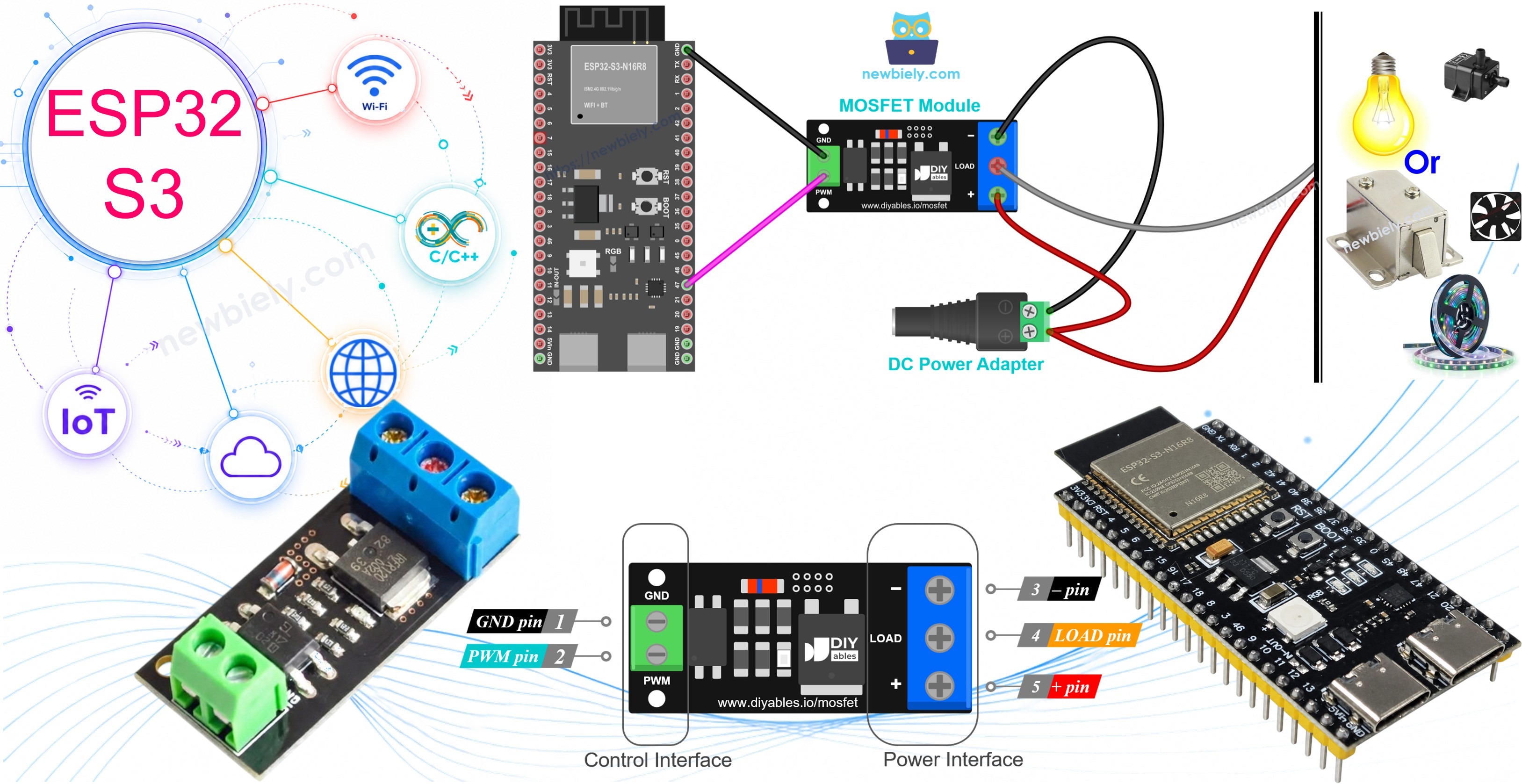
Hardware Preparation
Or you can buy the following kits:
| 1 | × | DIYables ESP32 S3 Starter Kit (ESP32 S3 included) | |
| 1 | × | DIYables Sensor Kit (18 sensors/displays) |
Additionally, some of these links are for products from our own brand, DIYables .
Overview of MOSFET Module
Each ESP32 S3 output pin can give just 3.3V and a few milliamps. One LED is happy with that. A 12V strip, fan, pump or heater is not. The MOSFET module is the helper in the middle: the GPIO pin only tells it what to do, and the module passes the heavy 12V current to the load.
You may ask why we do not use a relay. A relay clicks, wears out, and can only be fully on or fully off. The MOSFET is silent, has nothing that moves, reacts in a flash and keeps working for years. It also follows PWM, which is how you dim lights and change fan speed. Keep one rule in mind: DC loads only. AC mains must never go to this module.
How the Module Works
Right behind the PWM pin sit a small resistor and a PC817 optocoupler. Inside the PC817 there is a tiny LED facing a phototransistor, and the phototransistor feeds the MOSFET gate. A second resistor ties the gate down to 0V whenever the phototransistor is off. Because only light crosses the gap, there is no wire between the ESP32 S3 circuit and the 12V circuit, and even the two grounds stay apart on the module. The MOSFET itself is N-channel and sits on the low side, between the LOAD and − screws, while the strip hangs between + and LOAD. What happens next depends on what GPIO47 sends.
GPIO47 at 0V (LOW). Nothing pushes current into the PC817, so its LED stays dark and the phototransistor stays off. The pull-down resistor keeps the MOSFET gate at 0V, and the MOSFET acts like an open switch between LOAD and −. The minus lead of the strip now has no way back to the adapter, so no current flows and the strip sits at 0V, completely off. In the sketch, analogWrite(MOSFET_PIN, 0) or digitalWrite(MOSFET_PIN, LOW) creates this state.
GPIO47 at 3.3V (HIGH). The 3.3V level is plenty, because the LED in the PC817 needs only a few milliamps. That hidden LED lights up, the phototransistor conducts, and the MOSFET gate climbs to about half of the adapter voltage, so roughly 6V on a 12V supply. The MOSFET then turns fully on and behaves like a closed switch, with only a few milliohms of resistance on the AOD4184 and LR7843 or about 0.2Ω on the FR120N. Current now runs from the adapter + into the + screw, through the strip, into LOAD, across the MOSFET, out of the − screw and back to the adapter −. The strip receives almost all of the 12V and works at full power. analogWrite(MOSFET_PIN, 255) or digitalWrite(MOSFET_PIN, HIGH) gives this result.
GPIO47 sending PWM. Now the pin flips between LOW and HIGH around 1000 times per second, and the MOSFET copies every flip: on for each high part, off for each low part. The strip is fed with fast 12V pulses, and the duty cycle, the share of each period spent HIGH, sets the average. At 10% duty the load is on one tenth of the time and averages about 1.2V; at 50% it is on half of the time, about 6V and half power; at 90% it averages about 10.8V, close to full. An LED strip simply looks dimmer, since the flicker is far too quick for your eyes, while a fan, motor or pump turns more slowly because its spinning mass smooths out the pulses. In code this is analogWrite(MOSFET_PIN, value) with a value from 0 to 255, so the duty cycle is value / 255; the sketch on this page walks from 10% up to 100%. Do not push the frequency much higher than the 1 kHz default: the slow PC817 cannot keep up, the MOSFET stops switching cleanly, the load gets ragged pulses, and the chip turns hot.
Key Specifications
Size, pins, wiring and sketch are identical for all three. The chip on top is the one thing that changes, and it decides how many volts and amps you can switch.
| AOD4184 | LR7843 | FR120N | |
|---|---|---|---|
| MOSFET chip | AOD4184A (N-channel) | IRLR7843 (N-channel) | IRFR120N (N-channel) |
| Max load voltage (MOSFET rating) | 40V DC | 30V DC | 100V DC |
| Max current (MOSFET rating) | 50A | 161A | 9.4A |
| On-resistance RDS(on) | about 7 mΩ | about 3.3 mΩ | about 210 mΩ |
| Practical current, no heatsink | about 10–15A | about 15A | about 2A |
| Control signal | 3.3V / 5V logic, active HIGH | 3.3V / 5V logic, active HIGH | 3.3V / 5V logic, active HIGH |
| Isolation | PC817 optocoupler | PC817 optocoupler | PC817 optocoupler |
| PWM | yes, keep ≤ ~1 kHz | yes, keep ≤ ~1 kHz | yes, keep ≤ ~1 kHz |
| Load type | DC only | DC only | DC only |
Do not read 50A or 161A as the board rating. Those values belong to the chip alone, and the little PCB warms up far sooner. Let your load run for a while, then test the chip with a quick finger touch. Painfully hot means you should use a smaller load or fit a heatsink.
Not sure which one to get? For heavy current at 12V or 24V, such as long bright strips or big motors, choose the LR7843; it has the lowest resistance and runs coolest, but stop at 30V. The AOD4184 (sometimes marked D4184) sits in the middle and handles 12V, 24V and 36V jobs up to 40V. The FR120N is the pick for higher voltage, up to 100V, yet its higher resistance limits it to light 24V or 48V loads near 2A.
MOSFET Module Pinout
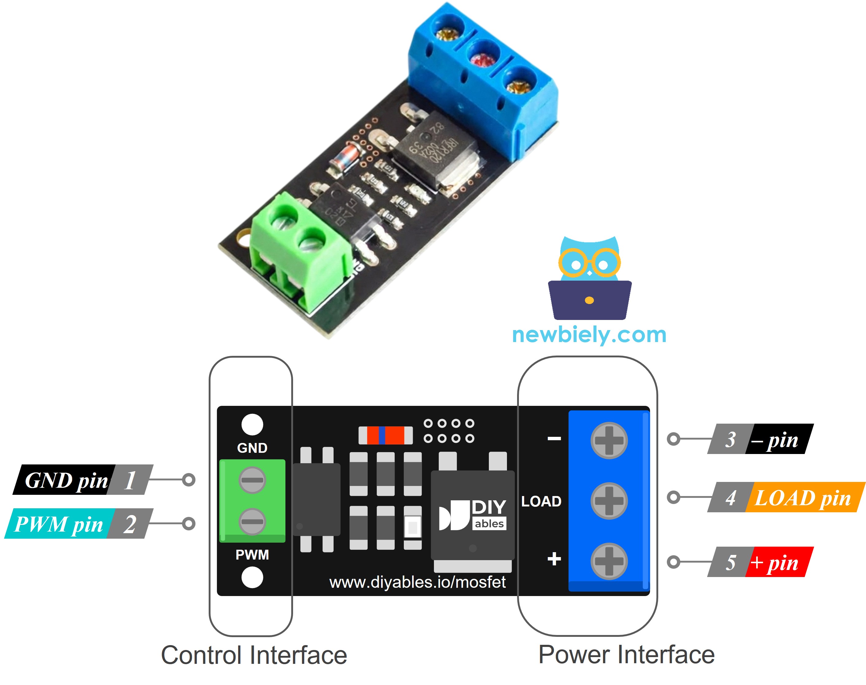
Two header pins face the ESP32 S3, and three screw terminals face the 12V side.
- PWM — signal in from ESP32 S3 GPIO47 (2.54mm pitch, so it plugs into a breadboard)
- GND — ground of the signal; wire it to ESP32 S3 GND
- + — 12V (or other) adapter plus lead AND plus lead of the strip or motor; both wires share this one terminal
- LOAD — minus lead of the strip or motor; the MOSFET drain switches this terminal
- − — adapter minus lead
Silkscreen names may vary slightly between production runs. Always go by what is printed on the module in your hand.
Wiring Diagram
Only two jumper wires link the ESP32 S3 to the module, GPIO47 to PWM plus a shared ground. Everything else is on the 12V side, where a DC power jack brings the adapter in and the strip connects to the + and LOAD screws. GPIO47 sits on the same header as TX and RX, and on the N16R8 board it outputs 3.3V like the other pins. On modules with a "V" in the name (such as R8V or R16V), GPIO47 runs at 1.8V, which may be too weak to light the optocoupler, so pick another free GPIO such as GPIO1 on those boards.
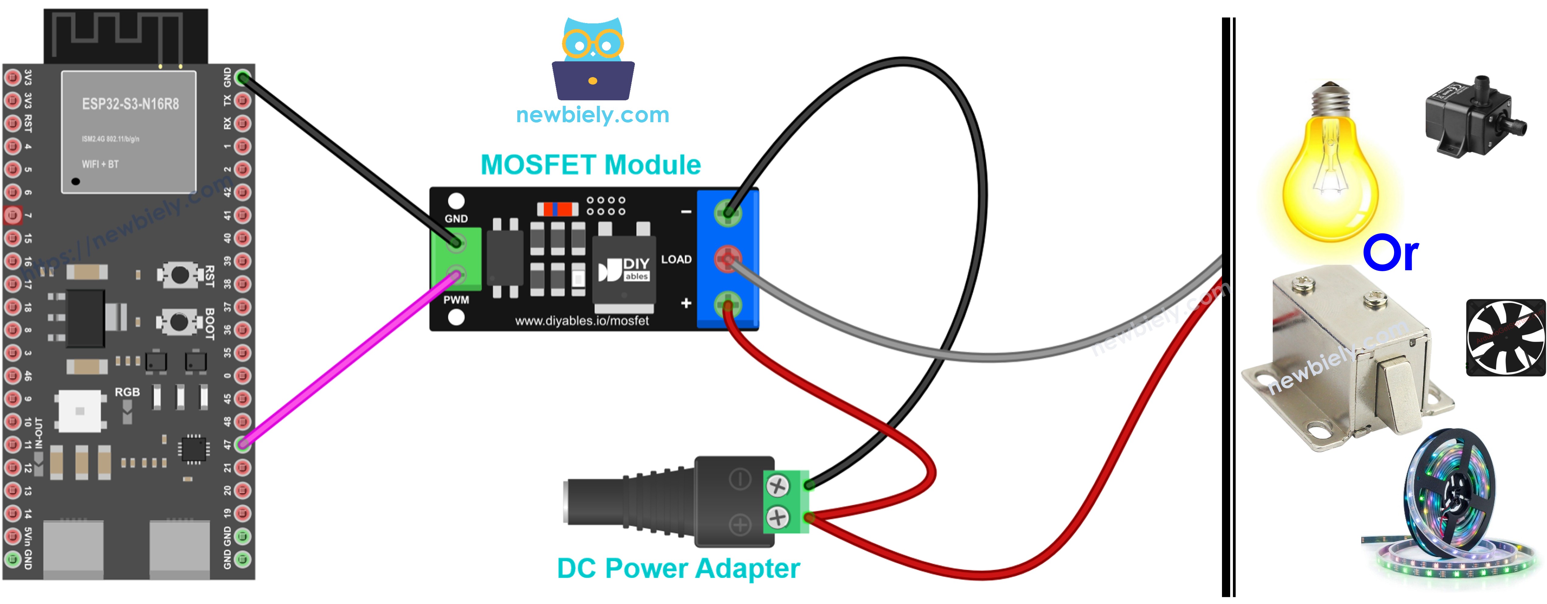
This image is created using Fritzing. Click to enlarge image
| From | To |
|---|---|
| ESP32 S3 GPIO47 | Module PWM |
| ESP32 S3 GND | Module GND |
| 12V adapter + (via DC power jack) | Module + |
| 12V adapter − (via DC power jack) | Module − |
| LED strip + | Module + (same terminal as the adapter +) |
| LED strip − | Module LOAD |
The strip is just the starting point. Below you will find six real loads hooked to the same module. GPIO47 and GND never move, so each picture only shows the 12V half: the adapter on + and −, the device on + and LOAD, and a diode where a coil is involved. Pick an adapter whose voltage equals the device rating, never under 6V, and size the module by the device current: the FR120N copes with roughly 2A on its own, while the AOD4184 and LR7843 take the heavier jobs. You can keep the sketch from this page for all six; just swap the fade for plain 100% and 0% (HIGH and LOW) when you drive a solenoid.
Hooking Up a 12V Fan
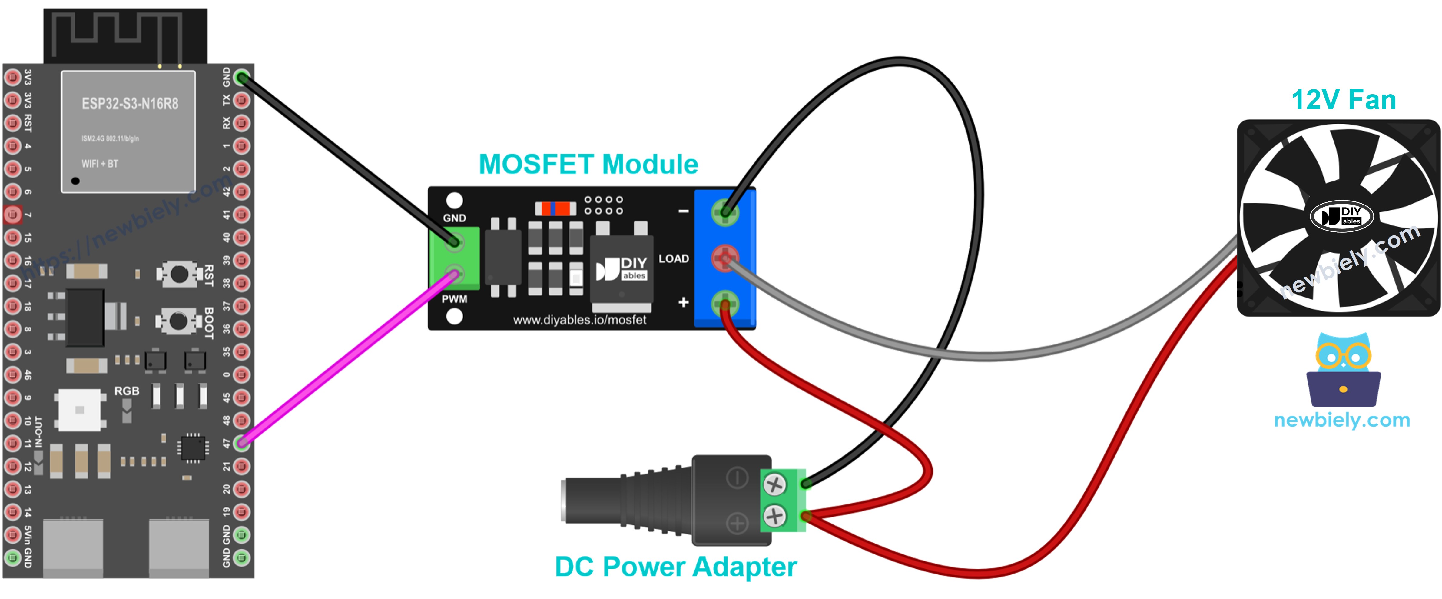
This image is created using Fritzing. Click to enlarge image
The red lead lands on + and the black lead on LOAD. A yellow third lead, if your fan has one, carries the speed signal and simply stays unconnected. Because a fan hides a small motor, give it the flyback diode described in the Safety Notes below; it costs pennies and does no harm. The duty cycle sets the speed, but many fans stall at very low values, so begin above about 30%.
Hooking Up a 12V Water Pump
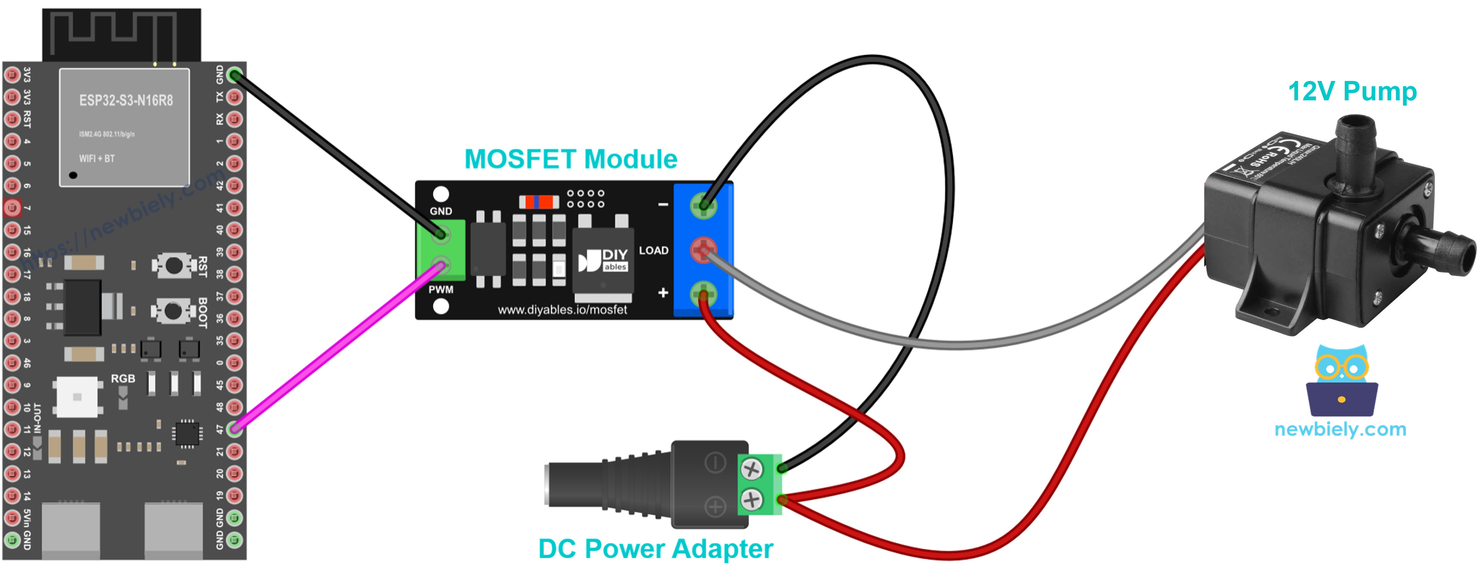
This image is created using Fritzing. Click to enlarge image
Plus lead to +, minus lead to LOAD, and the same diode across the pump terminals as on the fan. The duty cycle now sets how much water flows. Make sure the pump always has water around it, because running dry ruins it.
Hooking Up a 12V DC Motor
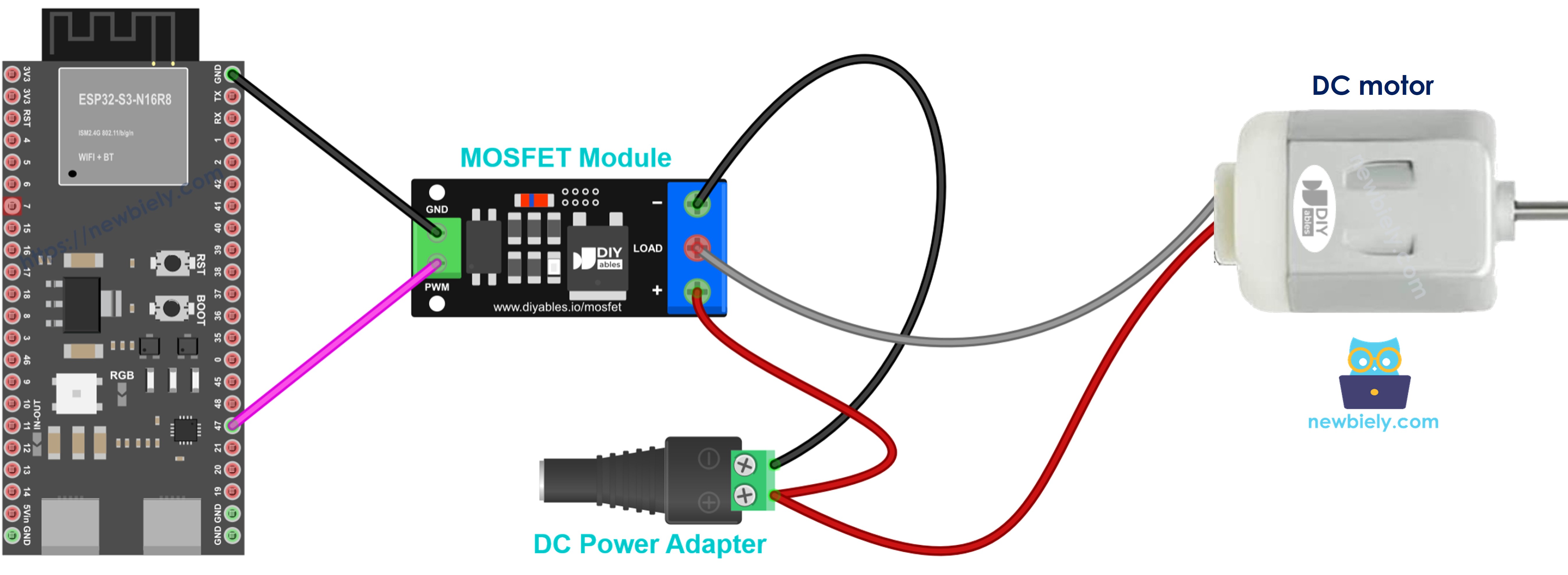
This image is created using Fritzing. Click to enlarge image
Motor + joins +, motor − joins LOAD, and the diode sits across both motor leads with its stripe on the plus side. The duty cycle sets the speed. The motor will only ever spin one way with this module; if you need it to reverse, move to a motor driver such as the L298N, explained in the ESP32 S3 - DC Motor tutorial.
Hooking Up a 12V Single-Color LED Strip
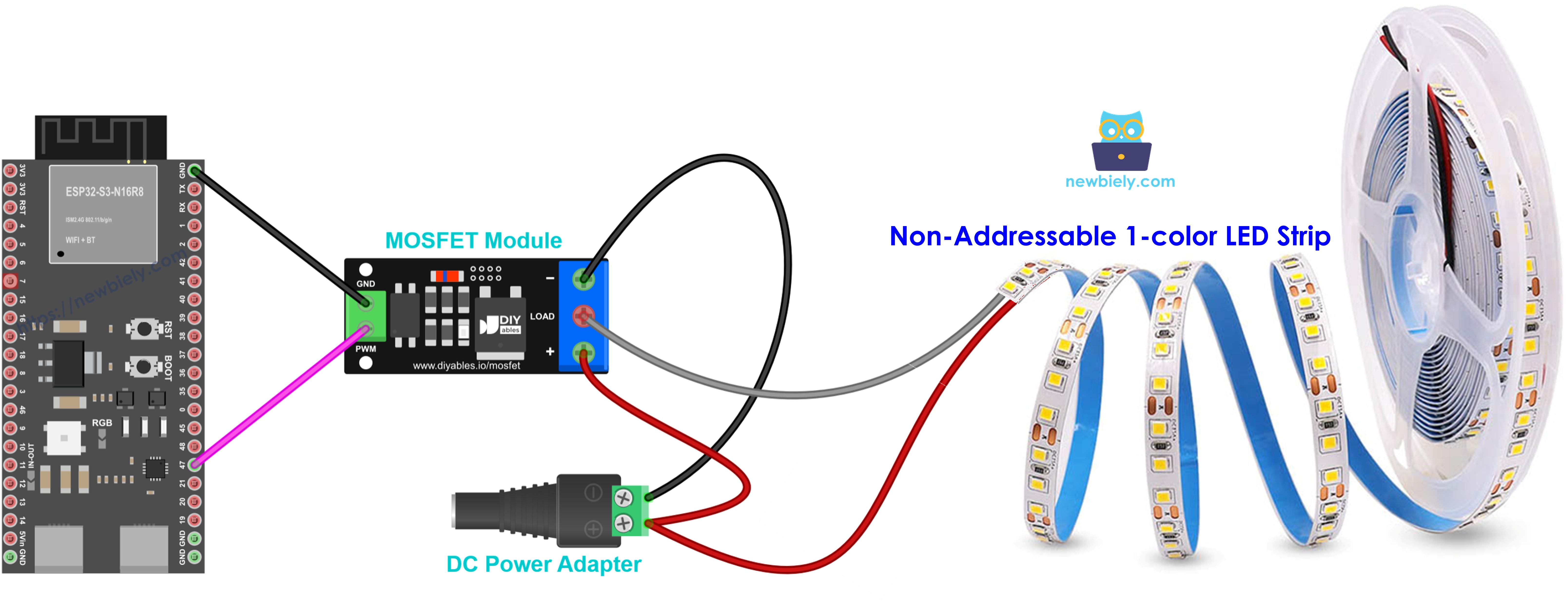
This image is created using Fritzing. Click to enlarge image
This is the wiring from the main diagram above, drawn on its own. The strip's plus pad (usually labeled 12V) goes to +, and its minus pad goes to LOAD. A strip acts like a plain resistor, so it needs no diode, and the duty cycle sets the brightness. Longer strips pull more current, so read the strip's rating before you choose a module. Note that RGB and addressable strips need a different setup; this picture covers single-color strips only.
Hooking Up a 12V Solenoid Valve
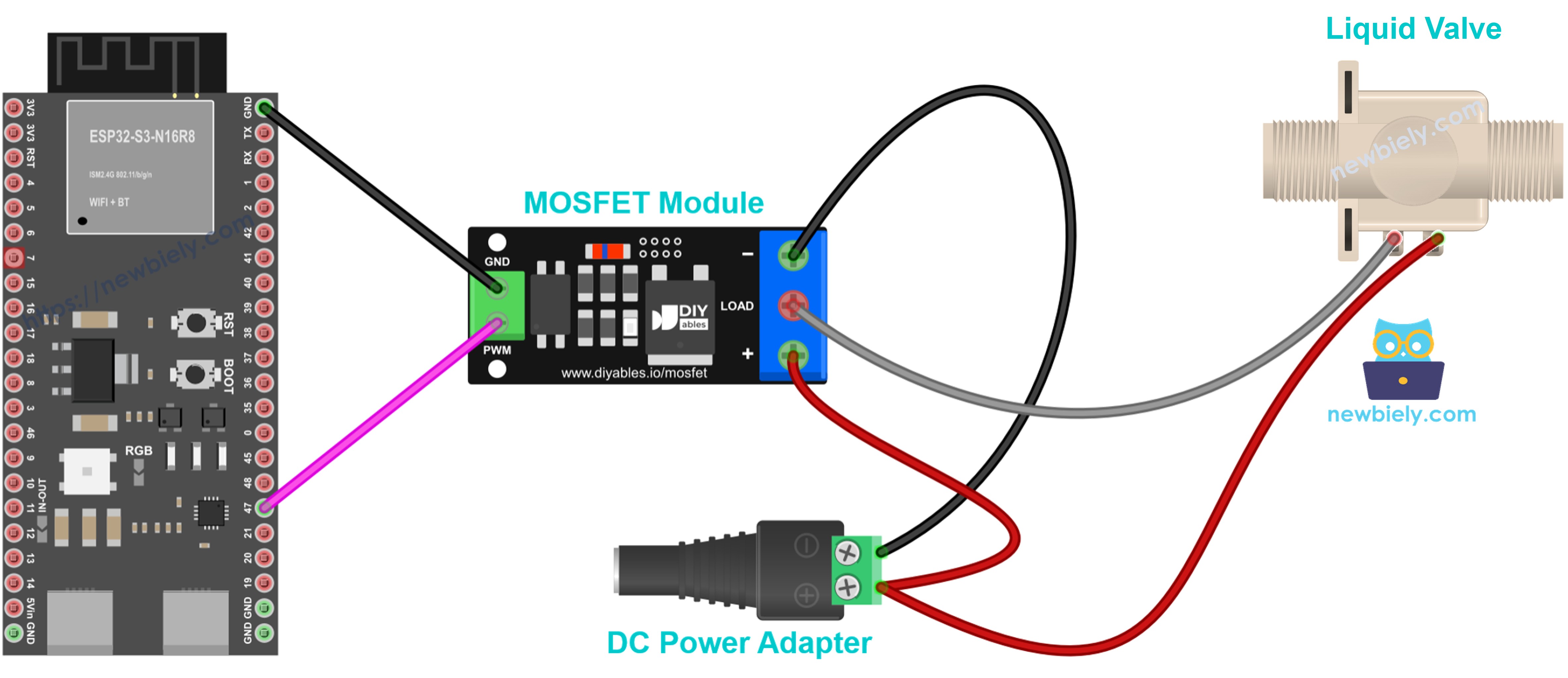
This image is created using Fritzing. Click to enlarge image
Valve + goes to + and valve − to LOAD, with a diode across the coil. A normally closed valve opens when it gets full power and shuts when the power is cut. Treat it as a pure on/off device and skip PWM.
Hooking Up a 12V Solenoid Lock
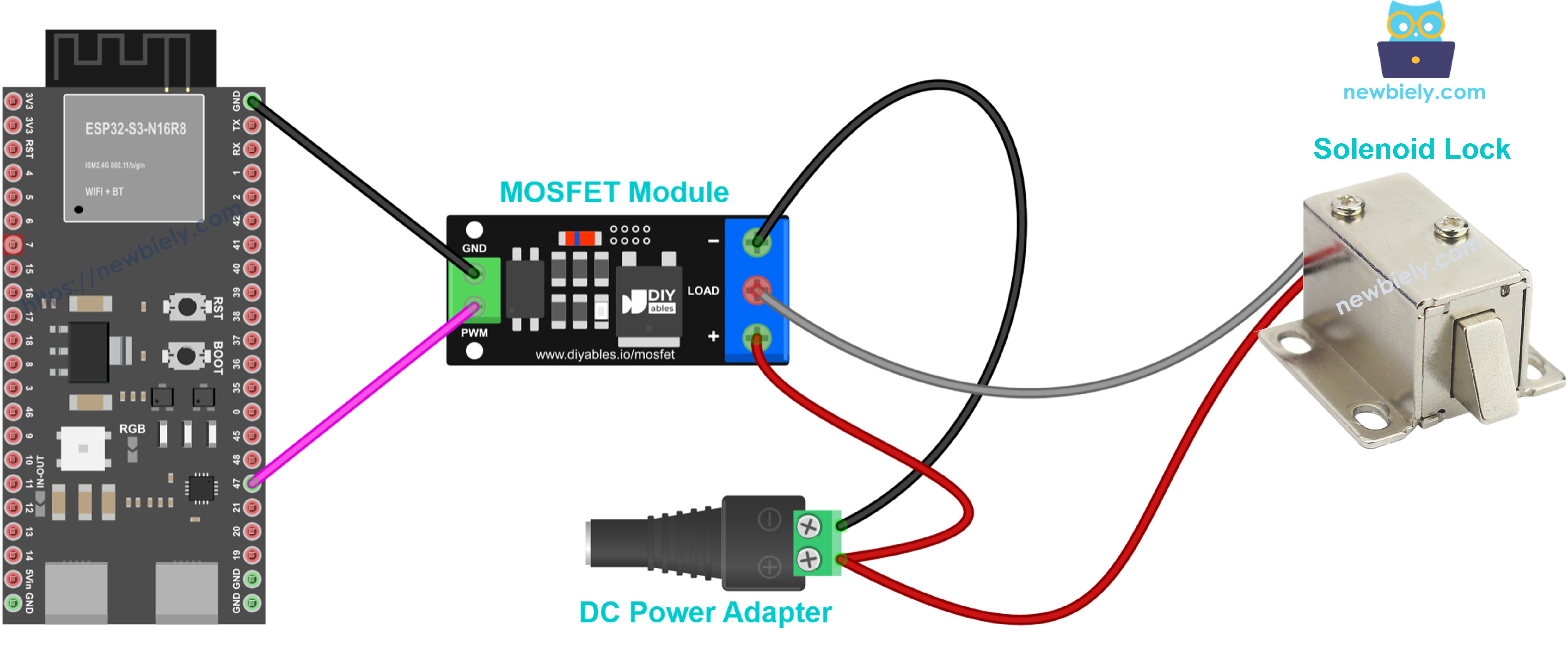
This image is created using Fritzing. Click to enlarge image
Lock + to +, lock − to LOAD, and once more a diode across the coil. Send it only 100% or 0%, never a dimmed level. The coil heats up when it stays energized, so pulse it on just long enough to release the latch, then switch it off.
Safety Notes
Keep the 12V wires away from every ESP32 S3 pin, because one slip can kill the board. The gate voltage is taken from the adapter, as explained in How the Module Works, so feed the load with 6V or more; a 5V adapter leaves the MOSFET half open, and heavy loads of several amps like 9V or higher. The module ships without a flyback diode, so for anything with a coil (motor, fan, pump, solenoid, relay) add a 1N5819 or 1N4007 across its two leads, stripe (cathode) toward load + and anode toward load −. Keep the PWM frequency near 500 Hz to 1 kHz; analogWrite() on the ESP32 S3 already runs at 1 kHz out of the box, which is a good match.
How To Program For MOSFET Module
You do not install anything extra here. GPIO47 is made an output, and analogWrite() sends a duty value between 0 (stopped) and 255 (full). The sketch keeps things human-friendly with a helper function named setLoad(): you give it a percent, map() scales it to 0–255, and the same line of text lands in the Serial Monitor.
ESP32 S3 Code - MOSFET Module
First the strip gets 100% for 2 seconds, then 0% for 2 seconds. After that the level climbs by 10% every 500 ms until it hits 100%, falls back down by 10% at the same speed until it reaches 0%, waits 1 second, and loops.
Detailed Instructions
- New to ESP32 S3? Complete our Getting Started with ESP32 S3 guide first.
- Build the circuit from the wiring diagram. Do not power the 12V adapter yet; that comes in step 6.
- Link the ESP32 S3 to your PC through a Type-C USB cable.
- In the Arduino IDE, choose the ESP32 S3 board from Tools > Board and the matching COM port from Tools > Port.
- Copy the sketch into an empty IDE window and click Upload.
- Once uploading finishes, power the 12V adapter.
- Launch the Serial Monitor with the baud rate at 9600.
- Look at the strip. It shines fully, goes out, then brightens in small steps and dims again.
- Pro Tip: A strip that never lights usually means a missing ground wire between the ESP32 S3 and the module GND pin, or a weak adapter. Measure the adapter; below about 6V the MOSFET cannot turn fully on.
Serial Monitor Output
These lines come back again and again while the ESP32 S3 is running.
Application and Project Ideas
Once the ESP32 S3 can set the power of a 12V load, many home and hobby projects become easy.
- Dimmable room light: Use a 12V LED strip as a lamp and set its brightness from a web page on the ESP32 S3.
- Smart cooling fan: Speed up a 12V fan as the room gets warmer, and slow it down when it cools.
- Plant watering pump: Run a small 12V pump for a few seconds when the soil is dry, with a flyback diode on the pump.
- Soft-start motor: Ramp a DC motor up slowly so it does not jump at start.
- Wake-up light: Fade an LED strip from dark to full over 20 minutes each morning.
- Solenoid door latch: Open a 12V solenoid lock for a moment when a correct code is entered.
Challenge Yourself
- Beginner: Change the step size from 10% to 5% and the delay from 500 ms to 100 ms to get a smoother fade.
- Intermediate: Add a potentiometer and map its reading to the load power, so you can turn a knob to dim the strip.
- Advanced: Let the ESP32 S3 serve a web page with a slider over WiFi, and set the MOSFET power from your phone.
Video Tutorial
Watch the step-by-step video walkthrough for this ESP32 S3 project below.