
ESP32 S3 - Door Sensor - Relay
A door sensor paired with a relay gives the ESP32 S3 the ability to automatically switch connected devices on or off in direct response to a door opening or closing. This tutorial guides you through wiring a magnetic reed-switch door sensor and a relay module to the ESP32 S3, writing the Arduino sketch that monitors door state, and testing the system by moving the magnet to watch the relay respond in real time.
What you'll build:
- A circuit connecting a magnetic door sensor and a relay module to the ESP32 S3
- A sketch that reads the door sensor state and switches the relay on when the door opens and off when it closes
- An automatic door-activated control system that can drive loads such as a 12V solenoid lock, buzzer, warning light, or cooling fan through the relay
- A foundation you can extend into home security systems, access control, or smart automation projects
Hardware Preparation
Or you can buy the following kits:
| 1 | × | DIYables ESP32 S3 Starter Kit (ESP32 S3 included) | |
| 1 | × | DIYables Sensor Kit (18 sensors/displays) |
Additionally, some of these links are for products from our own brand, DIYables .
Overview of Door Sensor and Relay
A magnetic door sensor consists of two parts — a reed switch and a magnet — that together form a normally-closed or normally-open circuit depending on whether the magnet is near the switch. When the door opens, the magnet moves away from the reed switch, the circuit state changes, and the ESP32 S3 detects the transition on its GPIO input pin. A relay module acts as an electronically controlled switch that lets the ESP32 S3 safely drive higher-voltage or higher-current loads — such as a 12V solenoid lock, a warning siren, or a cooling fan — using only a low-current GPIO output signal.
Key Specifications
We have dedicated tutorials covering each component in depth. Each tutorial contains detailed information and step-by-step instructions about hardware pinout, working principle, wiring connection to the ESP32 S3, and Arduino code. Learn more about them at the following links:
Wiring Diagram
Connect the door sensor and relay module to your ESP32 S3 following the diagram below, and verify every connection before applying power to the board. The door sensor's signal wire connects to an ESP32 S3 GPIO configured as an input, while the relay's control pin connects to a GPIO configured as an output.
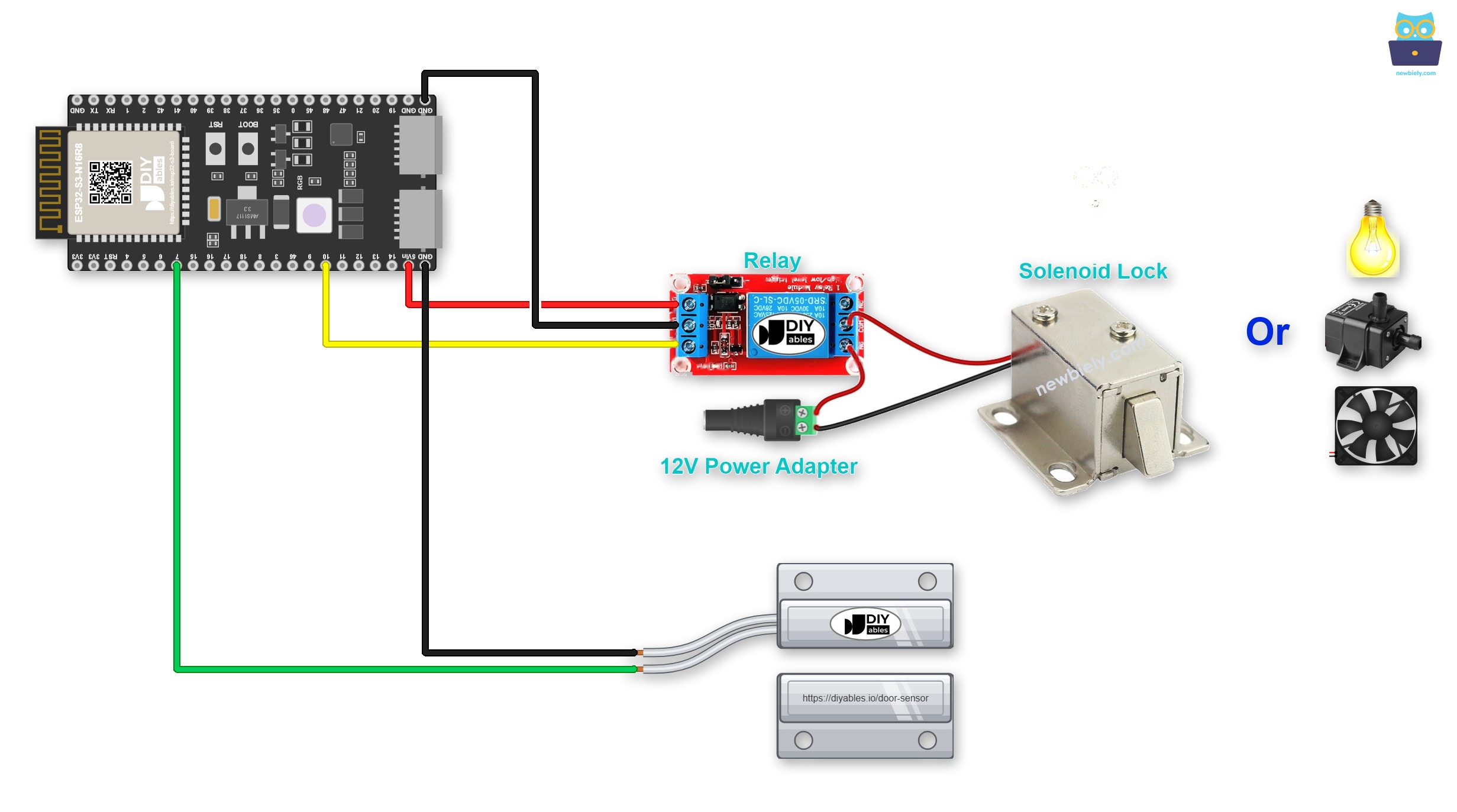
This image is created using Fritzing. Click to enlarge image
Module wires and thick wires often do not sit well in the female headers. Simply plug the ESP32 S3 into a Screw Terminal Block for ESP32 S3. This is how it looks with the screw terminal board:
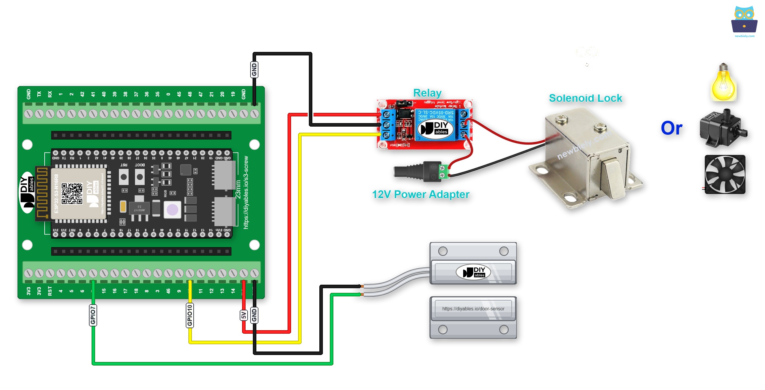
This image is created using Fritzing. Click to enlarge image
A GPIO Breakout Board for ESP32 S3 works too. Besides one S, 3.3V and GND pin for each GPIO, it has extra 3.3V and 5V pins:
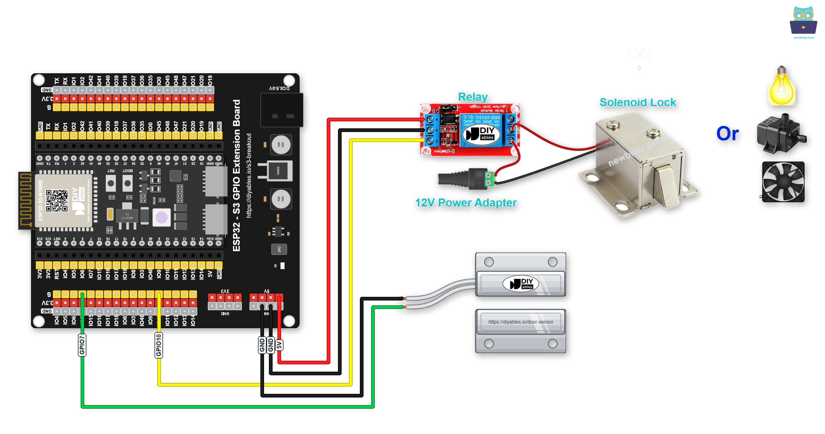
This image is created using Fritzing. Click to enlarge image
Safety Notes
Never connect mains voltage (110V/220V AC) to the relay load terminals unless your relay module is rated for it and you are confident working with high-voltage wiring; always use a low-voltage load such as a 12V solenoid or buzzer when prototyping. Keep the relay's high-voltage load wiring physically separated from the breadboard and jumper wires to prevent accidental contact, and ensure the relay module's VCC and GND are connected to the correct power rails on the ESP32 S3.
| Component | Pin | ESP32 S3 Pin |
|---|---|---|
| Door Sensor | Wire 1 | GND |
| Door Sensor | Wire 2 | GPIO7 |
| Relay Module | VCC | 5V |
| Relay Module | GND | GND |
| Relay Module | IN | GPIO10 |
ESP32 S3 Code - Door Sensor - Relay
The following code reads the door sensor state on every loop iteration and drives the relay output accordingly — turning the relay on when the door is detected as open and turning it off when the door is closed. The sketch uses the built-in pull-up resistor on the ESP32 S3 GPIO input so no external resistor is needed for the door sensor connection.
In the above code, the ESP32 S3 continuously monitors the door sensor pin and immediately updates the relay state whenever a door open or close event is detected, printing the new state to the Serial Monitor for easy debugging.
Detailed Instructions
- New to ESP32 S3? Complete our Getting Started with ESP32 S3 guide first.
- Wire the door sensor and relay module to the ESP32 S3 following the wiring diagram above.
- Connect the ESP32 S3 board to your PC using a USB Type-C cable.
- Open Arduino IDE on your PC.
- Select the correct ESP32 S3 board and COM port from the Tools menu.
- Copy the above code and paste it into Arduino IDE.
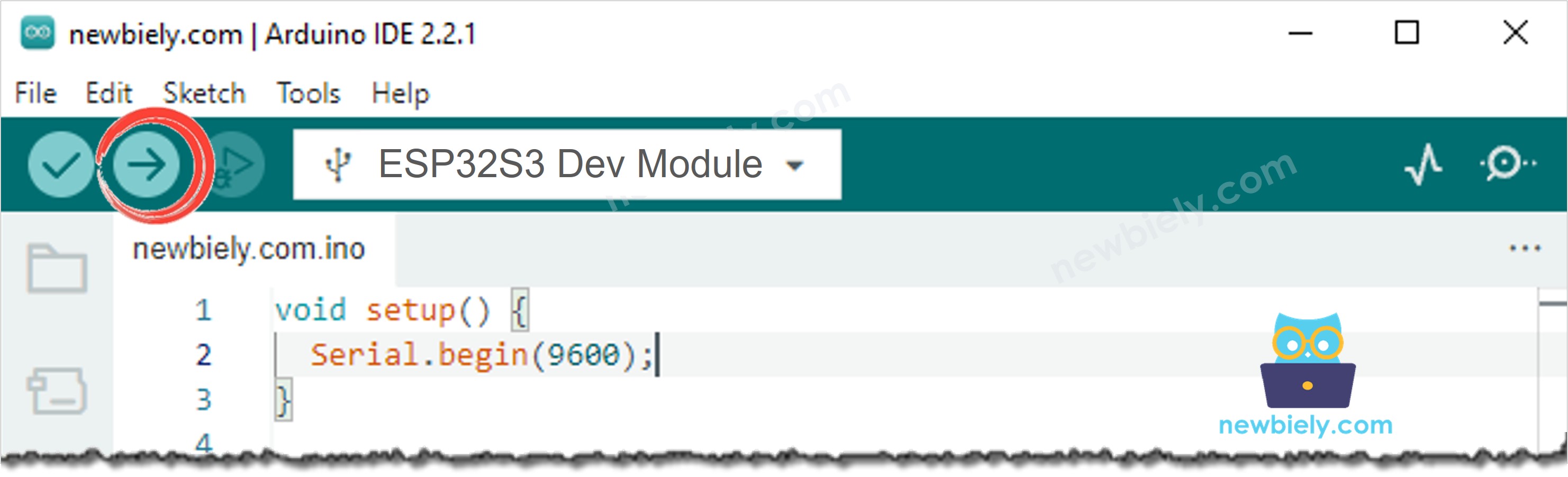
- Click the Upload button to compile and upload the code to your ESP32 S3.
- Open the Serial Monitor at 9600 baud.
- Move the magnet close to the reed switch, then move it away from the reed switch.
- Observe the relay state change in the Serial Monitor and listen for the relay clicking on and off.
- Pro Tip: For toggling the relay each time the door opens or closes rather than holding it on while open, see the ESP32 S3 - Door Sensor Toggles Relay tutorial.
Serial Monitor Output
The following Serial Monitor output shows the ESP32 S3 reading the door sensor and switching the relay in response to door open and close events. Each line is timestamped so you can verify the response time and confirm that the relay state tracks the door state correctly.
Application and Project Ideas
Once the ESP32 S3 can automatically switch a relay in response to door sensor events, you can adapt this project into a wide range of practical security, automation, and notification systems.
- Intruder alarm: Connect a 12V active buzzer or siren to the relay so it sounds immediately whenever a door or window is opened unexpectedly.
- Automatic lighting: Trigger a relay-controlled light or LED strip to turn on when a door opens and switch off after the door closes, perfect for pantries or closets.
- Access control log: Pair the door sensor relay with the ESP32 S3 Wi-Fi capability to log every door open event with a timestamp to a cloud server or SD card.
- Solenoid lock controller: Use the relay to power a 12V solenoid lock, automatically securing a door when it is closed and releasing it when an authorised trigger is received.
- Cooling fan activation: Connect a 12V fan to the relay to ventilate an enclosure or room whenever a door is opened, useful in server rooms or storage areas.
- Email or SMS notification: Extend the project with Wi-Fi so the ESP32 S3 sends an email or SMS alert whenever the door sensor triggers the relay, giving remote awareness of door activity.
Video Tutorial
Watch the step-by-step video walkthrough for this ESP32 S3 project below.
Challenge Yourself
Now that you can automatically control a relay with a door sensor on the ESP32 S3, try these progressively harder challenges to deepen your understanding and build a more capable system.
- Beginner: Modify the sketch to print a counter to the Serial Monitor that tracks how many times the door has been opened since the board was powered on.
- Beginner: Add an LED indicator that mirrors the relay state, lighting up when the relay is on and turning off when it is off, so the door state is visible at a glance.
- Intermediate: Implement a time-delay feature using millis() so the relay stays on for a fixed number of seconds after the door opens before turning off automatically.
- Intermediate: Add a second door sensor to monitor two separate doors or windows independently, each controlling its own relay output.
- Advanced: Combine the door sensor relay logic with Wi-Fi and an MQTT broker so door events are published to a home automation platform such as Home Assistant in real time.
- Advanced: Build a simple access-control system that only activates the relay (to unlock a solenoid lock) when a correct RFID card is scanned while the door sensor detects the door is in the closed position.