
ESP32 S3 - Ultrasonic Sensor - LCD
The HC-SR04 ultrasonic sensor combined with an LCD I2C display gives the ESP32 S3 a self-contained distance-reading station — no laptop required once the sketch is uploaded. This tutorial walks you through wiring both components to the ESP32 S3 and writing the Arduino code that takes measurements and prints them to the screen in real time.
What you'll build:
- A circuit connecting an HC-SR04 ultrasonic sensor and an LCD I2C display to the ESP32 S3
- A sketch that triggers the sensor, calculates the distance, and updates the LCD every 500 milliseconds
- A portable, stand-alone distance meter that displays readings without needing a Serial Monitor
- A foundation you can extend into proximity alarms, parking assistants, or liquid level monitors
Hardware Preparation
Or you can buy the following kits:
| 1 | × | DIYables ESP32 S3 Starter Kit (ESP32 S3 included) | |
| 1 | × | DIYables Sensor Kit (18 sensors/displays) |
Additionally, some of these links are for products from our own brand, DIYables .
Buy Note: Most LCD I2C displays available on the market are 5V displays. They may work with this board, but it is unsafe and can damage the board. We strongly recommend using the 3.3V LCD I2C display recommended above.
Overview of Ultrasonic Sensor and LCD
The HC-SR04 ultrasonic sensor emits a high-frequency sound pulse and measures how long the echo takes to return, letting the ESP32 S3 calculate the distance to any object in front of it without making physical contact. Pairing it with an LCD I2C display turns the result into a continuously updated readout that is easy to read at a glance, making it ideal for stand-alone instruments and interactive exhibits.
Key Specifications
We have dedicated tutorials covering each component in depth. Each tutorial contains detailed information and step-by-step instructions about hardware pinout, working principle, wiring connection to the ESP32 S3, and Arduino code. Learn more about them at the following links:
Wiring Diagram
Connect the HC-SR04 and the LCD I2C display to your ESP32 S3 following the diagram below, and double-check every connection before powering the board. Both the ultrasonic sensor and the LCD operate at 5V, so use the 5V (VBUS) pin on the ESP32 S3 when powering via USB.
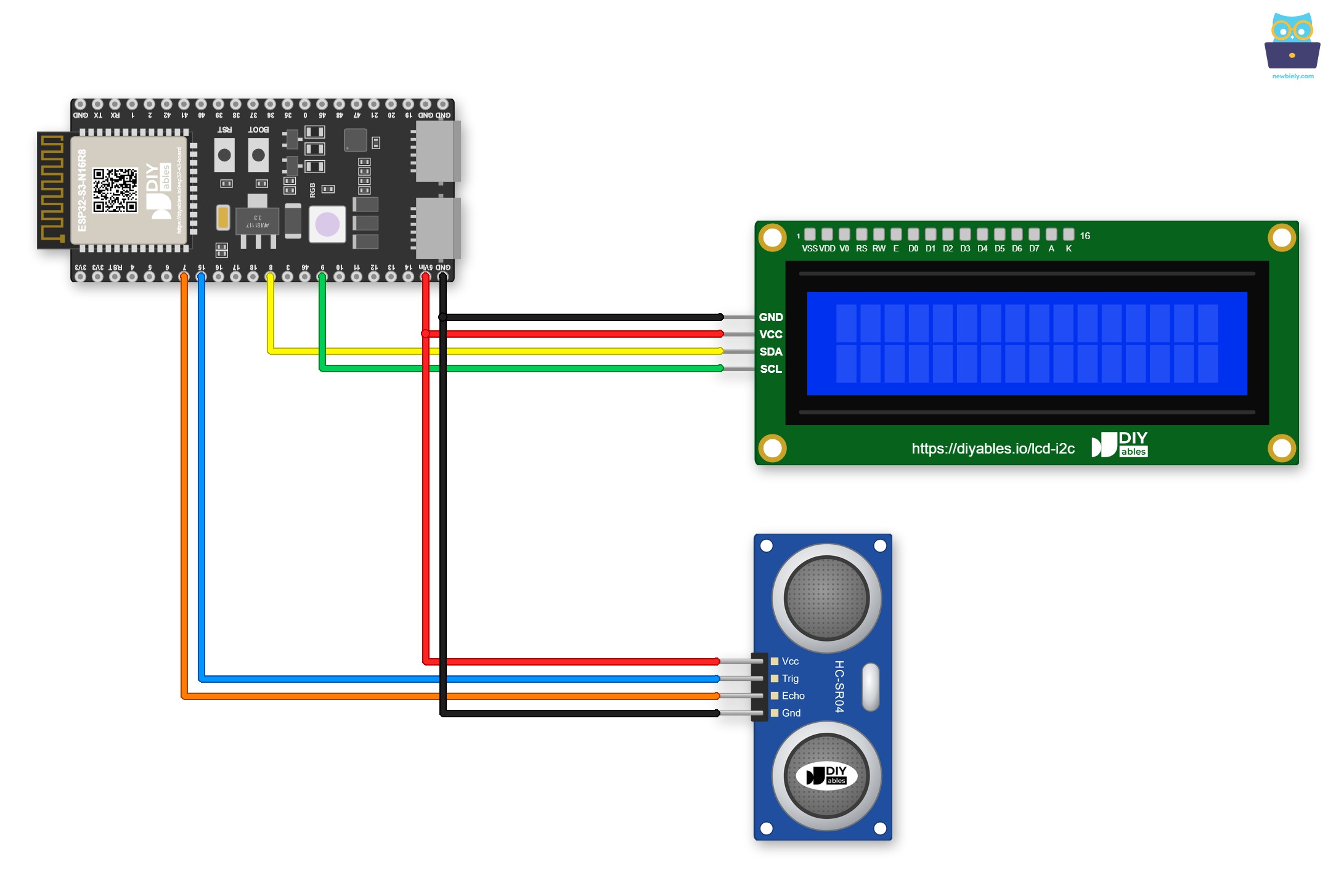
This image is created using Fritzing. Click to enlarge image
Do you want the wiring to stay in place? In this case, use a Screw Terminal Block for ESP32 S3. The ESP32 S3 plugs into it, and each pin gets a screw terminal. Below is the wiring diagram with the screw terminal board.
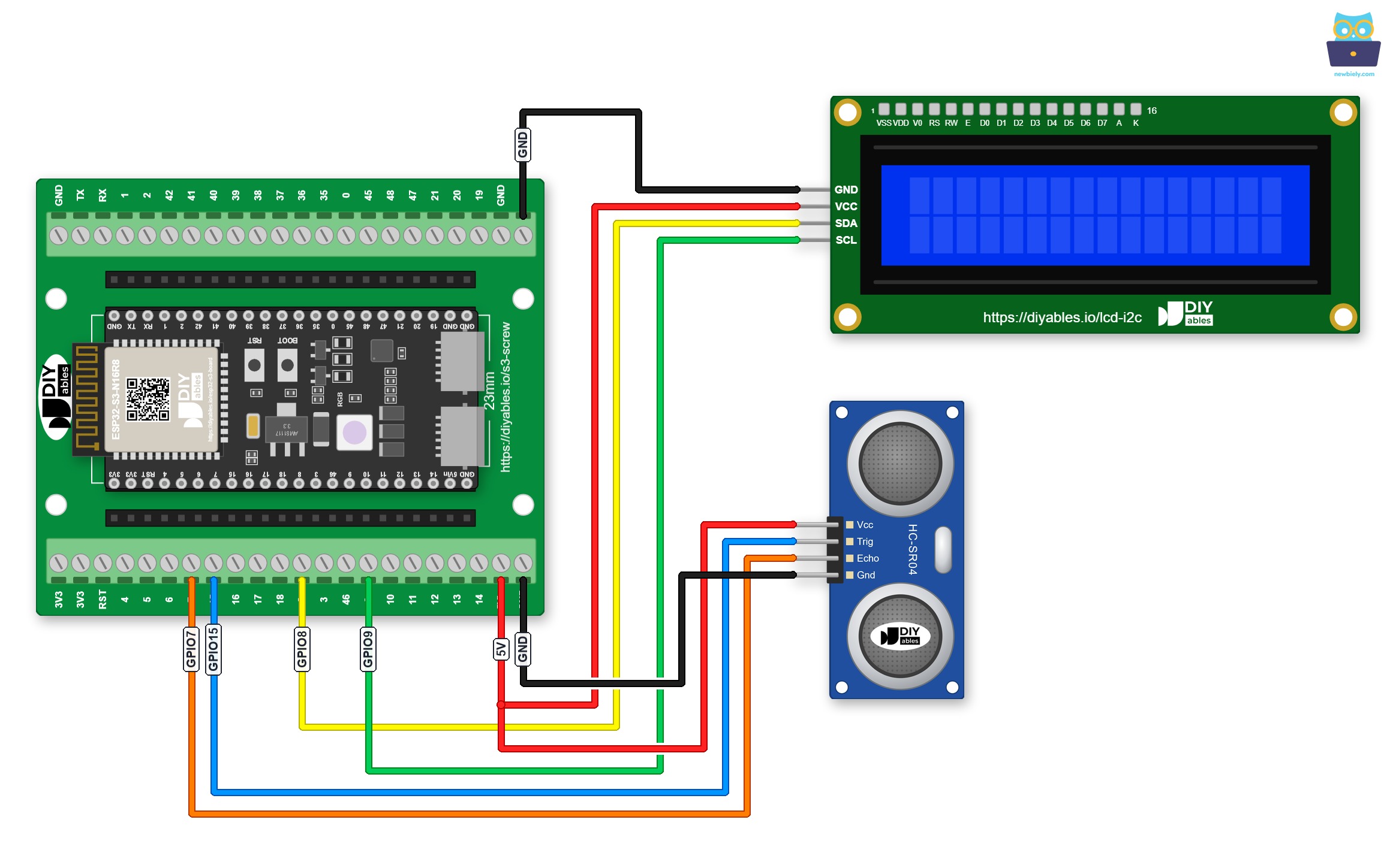
This image is created using Fritzing. Click to enlarge image
Here is the same circuit with a GPIO Breakout Board for ESP32 S3, which breaks out every GPIO to pin headers:
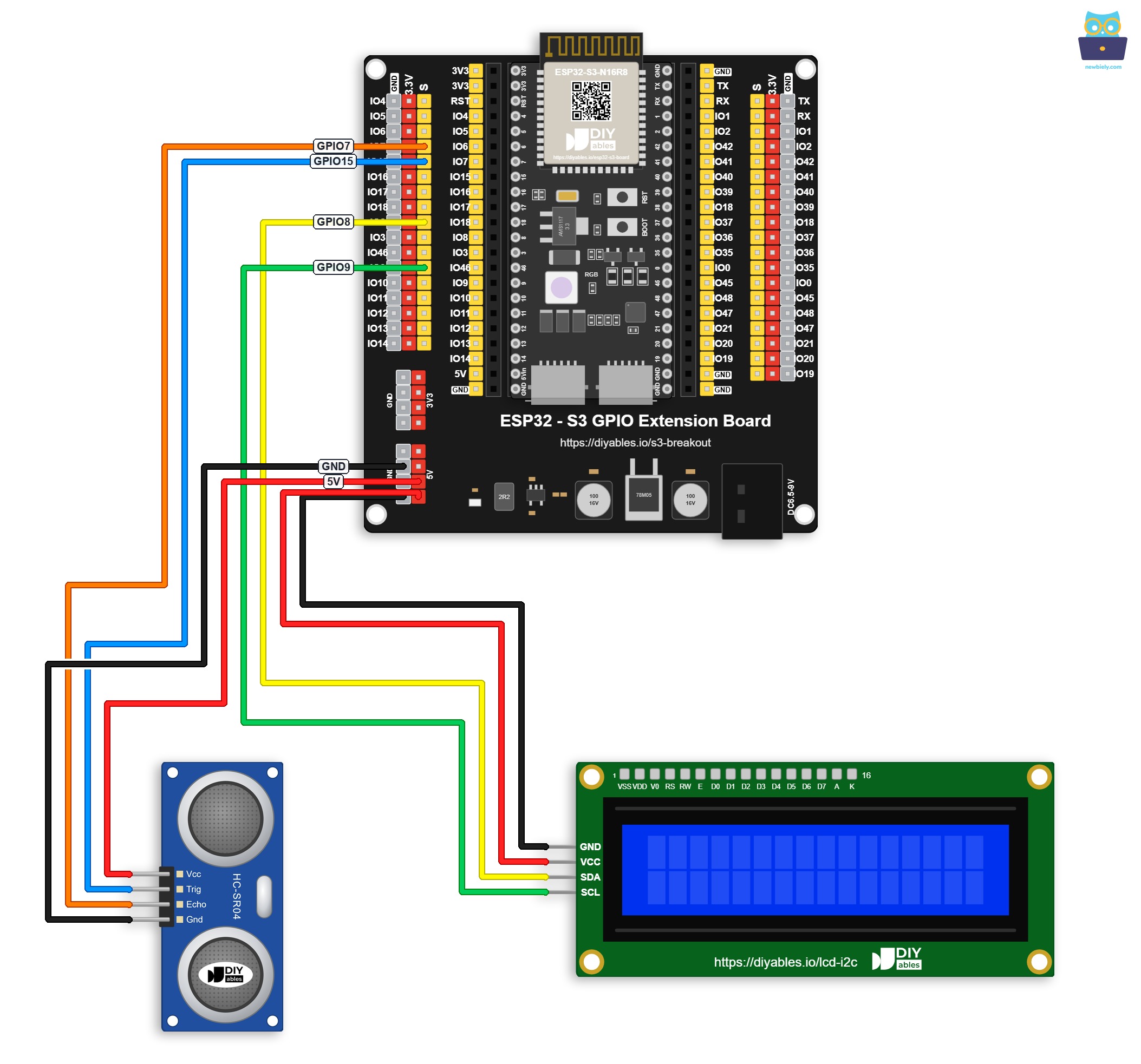
This image is created using Fritzing. Click to enlarge image
Safety Notes
Always connect the HC-SR04 VCC and the LCD VCC pins to the 5V rail rather than the 3.3V rail — both components require 5V to operate correctly and will produce unreliable results at lower voltages. Keep signal wires short and away from power wires to minimize noise on the ECHO line, which could produce erratic distance readings.
| Component | Pin | ESP32 S3 Pin |
|---|---|---|
| Ultrasonic Sensor | VCC | 5V |
| Ultrasonic Sensor | GND | GND |
| Ultrasonic Sensor | TRIG | GPIO15 |
| Ultrasonic Sensor | ECHO | GPIO7 |
| LCD I2C | VCC | 5V |
| LCD I2C | GND | GND |
| LCD I2C | SCL | GPIO9 (I2C Clock) |
| LCD I2C | SDA | GPIO8 (I2C Data) |
ESP32 S3 Code
The following code triggers the HC-SR04 ultrasonic sensor every 500 milliseconds, reads the echo pulse duration, converts it to centimeters, and displays the result on the LCD I2C screen. It uses the DIYables LCD I2C library to keep the display logic clean and readable, requiring only a few lines to initialize and update the screen.
※ NOTE THAT:
The LCD I2C address can be different from each manufacturer. In the code, we used address of 0x27 that is specified by DIYables manufacturer. If your LCD displays nothing, try address 0x3F instead.
Detailed Instructions
- New to ESP32 S3? Complete our Getting Started with ESP32 S3 guide first.
- Wire the ultrasonic sensor and LCD I2C to the ESP32 S3 following the wiring diagram above.
- Connect the ESP32 S3 board to your PC using a USB Type-C cable.
- Open Arduino IDE on your PC.
- Select the correct ESP32 S3 board and COM port from the Tools menu.
- Click the Libraries icon on the left bar of the Arduino IDE.
- Type "DIYables LCD I2C" in the search box, then look for the DIYables_LCD_I2C library by DIYables.
- Click the Install button to install the DIYables_LCD_I2C library.
- Search for DIYables LCD I2C created by DIYables.io and click the Install button.
- Copy the above code and paste it into Arduino IDE.
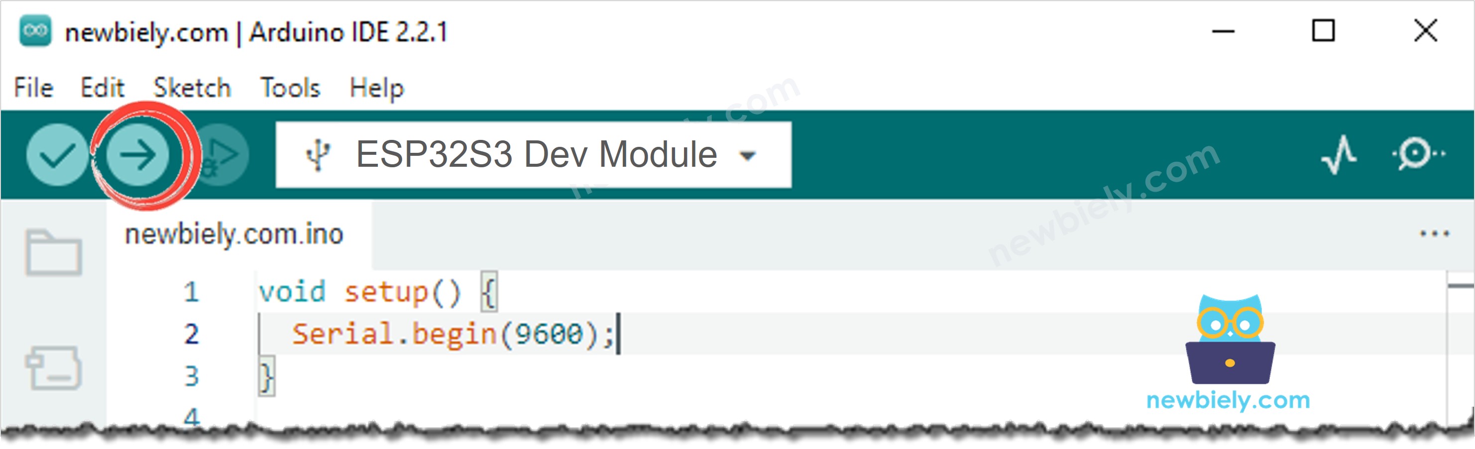
- Click the Upload button to compile and upload the code to your ESP32 S3.
- Hold your hand or an object at various distances in front of the sensor.
- Watch the distance reading update on the LCD display in real time.
- Pro Tip: If the LCD displays nothing, adjust the contrast potentiometer on the back of the LCD module and verify the I2C address in the code matches your module (try 0x3F if 0x27 does not work).
Serial Monitor Output
The following Serial Monitor output shows the ESP32 S3 reading distance from the HC-SR04 sensor and updating the LCD at regular intervals. Each line is timestamped so you can verify the update rate and check that readings change as you move an object closer or farther away.
Application and Project Ideas
Once you have distance readings showing up on the LCD with your ESP32 S3, you can adapt this project into a wide range of practical applications across home automation, robotics, and industrial monitoring.
- Parking assistant: Mount the sensor in a garage and display real-time distance as a vehicle approaches a stop line.
- Liquid level monitor: Aim the sensor downward into a tank and display the measured depth as a fill percentage on the LCD.
- Proximity alarm: Trigger a buzzer when the displayed distance drops below a configurable threshold.
- Obstacle detection robot: Feed the LCD distance into navigation logic to steer an autonomous vehicle around obstacles.
- People counter: Detect when someone passes a doorway and increment a visitor count shown on the LCD.
- Height measurement station: Mount the sensor overhead and display the calculated height of an object or person standing below.
Video Tutorial
Watch the step-by-step video walkthrough for this ESP32 S3 project below.
Challenge Yourself
Now that you can display live distance readings on the LCD with your ESP32 S3, try these progressively harder challenges to deepen your understanding and extend the project into something more capable.
- Beginner: Modify the sketch to display the distance in both centimeters and inches on separate rows of the LCD.
- Beginner: Add a second line to the LCD that shows whether the detected object is "NEAR" (under 20 cm) or "FAR" (over 20 cm).
- Intermediate: Implement a three-level proximity indicator on the LCD — "SAFE", "CLOSE", and "DANGER" — with matching LED colors using an RGB LED.
- Intermediate: Apply a five-sample moving average to the distance readings to smooth out noise and produce a steadier LCD display.
- Advanced: Add a push button that lets the user set a custom alert threshold, stored in flash memory so it survives a power cycle.
- Advanced: Extend the project with Wi-Fi so the ESP32 S3 sends distance readings to a web dashboard while simultaneously updating the LCD.