
ESP32 S3 - Motion Sensor - Servo Motor
This tutorial shows you how to use the ESP32 S3 with an HC-SR501 PIR motion sensor to automatically control a servo motor based on detected movement. By combining passive infrared motion detection with precise angular actuation, you can build responsive presence-triggered systems that react instantly when someone enters the sensing area.
What you'll build:
- An ESP32 S3 circuit with an HC-SR501 motion sensor and a servo motor wired to the board
- A sketch that reads the motion sensor output continuously on a digital pin
- A servo motor that rotates to 90° automatically when motion is detected
- A servo motor that returns to 0° automatically when no motion is detected
https://newbiely.com/images/cover/esp32-s3-motion-sensor-servo-motor.jpg
Hardware Preparation
Or you can buy the following kits:
| 1 | × | DIYables ESP32 S3 Starter Kit (ESP32 S3 included) | |
| 1 | × | DIYables Sensor Kit (18 sensors/displays) |
Additionally, some of these links are for products from our own brand, DIYables .
Buy Note: For controlling multiple servo motors, use the PCA9685 16 Channel PWM Servo Driver Module to save MCU pins and simplify wiring.
Overview of Servo Motor and Motion Sensor
The HC-SR501 PIR motion sensor and servo motor are a powerful combination for the ESP32 S3: the sensor detects infrared radiation changes caused by moving warm bodies and outputs a clean digital HIGH/LOW signal, while the servo delivers precise, repeatable angular movement in direct response to that signal. Together they enable a wide class of presence-aware automation projects — from automatic doors and security triggers to lighting control arms and access barriers.
Key Specifications
We have specific tutorials about each component covering detailed hardware pinout, working principles, wiring to the ESP32 S3, and full code examples. Learn more at the links below:
Wiring Diagram
Connect the HC-SR501 and the servo motor to your ESP32 S3 as shown in the diagram below. The HC-SR501 operates at 5V so connect its VCC pin to the 5V rail, and ensure the servo motor power wire is also supplied from 5V for reliable torque.
Safety Notes
Servo motors can briefly draw several hundred milliamps under load, which can stress the ESP32 S3's USB supply if used for extended periods. For bench testing, the USB port is generally sufficient; for any deployment scenario, power the servo from a dedicated 5V external supply and share only the GND rail with the ESP32 S3. The HC-SR501 motion sensor also requires 5V on its VCC pin — connecting it to 3.3V will result in incorrect or absent trigger signals.
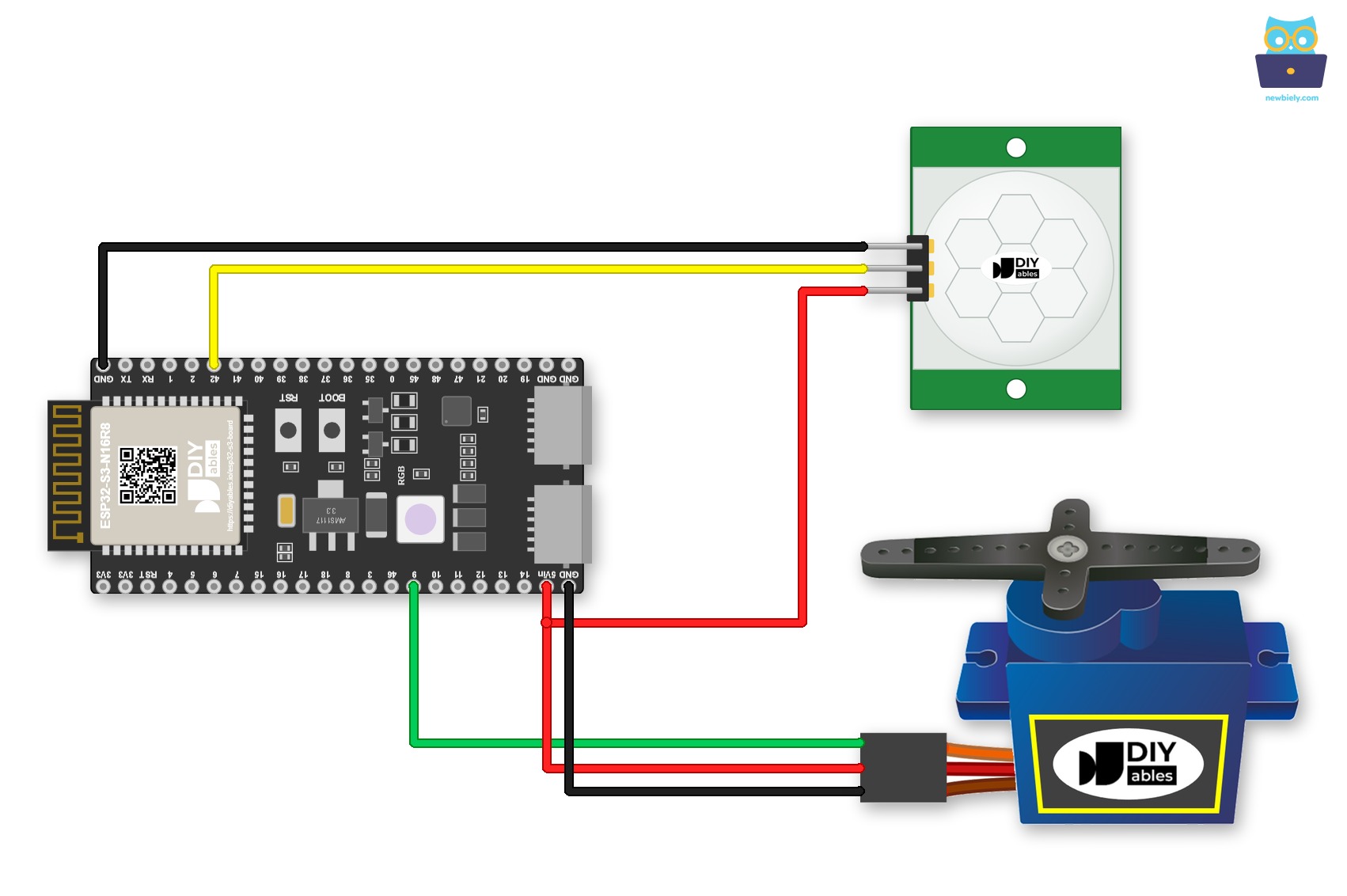
This image is created using Fritzing. Click to enlarge image
| Component | Pin | ESP32 S3 Pin |
|---|---|---|
| Motion Sensor | VCC | 5V |
| Motion Sensor | GND | GND |
| Motion Sensor | OUT | GPIO42 |
| Servo Motor | GND (Brown/Black) | GND |
| Servo Motor | VCC (Red) | 5V |
| Servo Motor | Signal (Yellow/Orange) | GPIO9 |
Loose wires are a common cause of strange bugs. You can plug the ESP32 S3 into a Screw Terminal Block for ESP32 S3 and connect the wires to its screw terminals. Below is the wiring diagram with the screw terminal board.
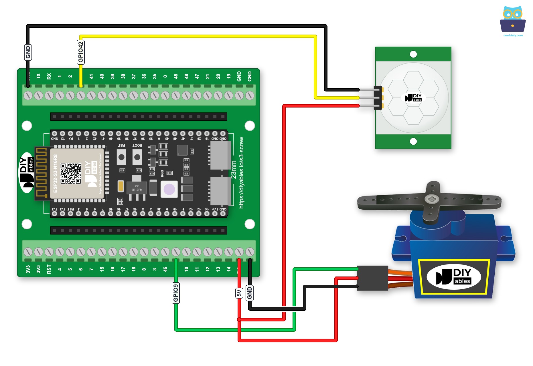
This image is created using Fritzing. Click to enlarge image
Here is the same circuit with a GPIO Breakout Board for ESP32 S3, which breaks out every GPIO to pin headers:
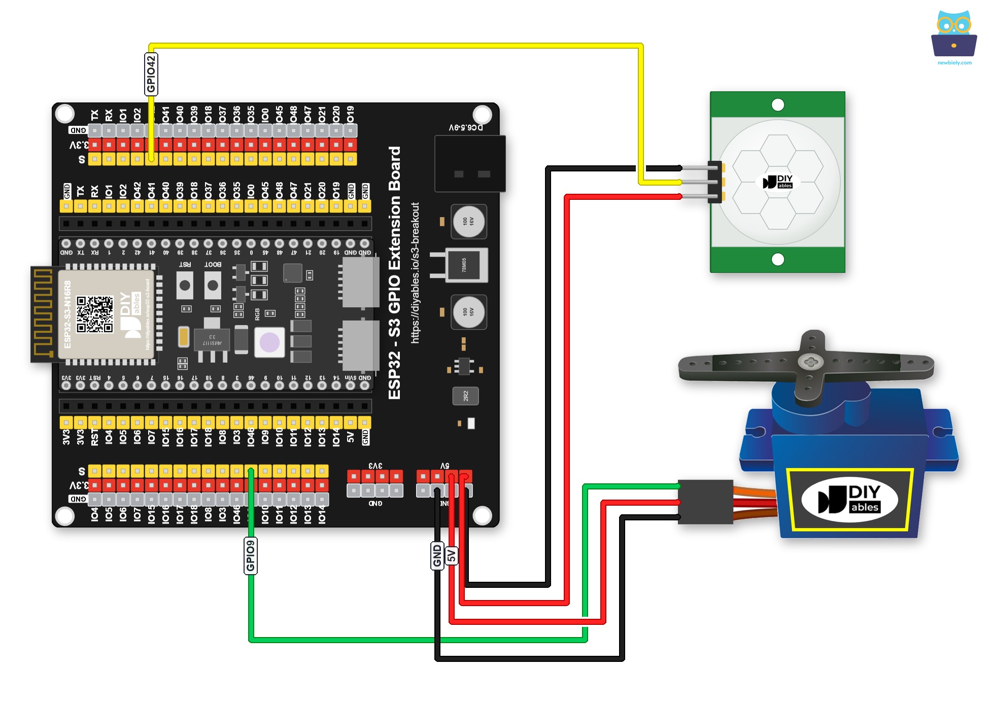
This image is created using Fritzing. Click to enlarge image
Initial Setting
| Detection Range Adjuster | Fully screw it in the clockwise direction. |
| Time Delay Adjuster | Fully screw it in the anti-clockwise direction. |
| Repeat Trigger Selector | Put jumper like the below image. |
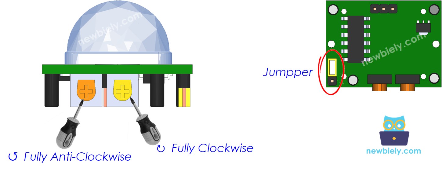
ESP32 S3 Code - Motion Sensor Controls Servo Motor
The following code uses the ESP32 S3 to read the digital output of the HC-SR501 motion sensor and translate detected motion into a servo motor angle. When motion is detected, the ESP32 S3 commands the servo to rotate to 90°; when motion is no longer present, the servo returns to 0°. The ESP32Servo library handles PWM signal generation for the servo, keeping the sketch straightforward and easy to adapt.
Detailed Instructions
- New to ESP32 S3? Complete our Getting Started with ESP32 S3 guide first.
- Wire the components: Follow the wiring diagram shown above to connect the HC-SR501 motion sensor and servo motor to your ESP32 S3.
- Connect ESP32 S3: Use a USB Type-C cable to connect the board to your computer.
- Setup Arduino IDE: If this is the first time you use ESP32 S3, see how to setup environment for ESP32 S3 on Arduino IDE.
- Select your board: Choose the ESP32 S3 board and its COM port under Tools in Arduino IDE.
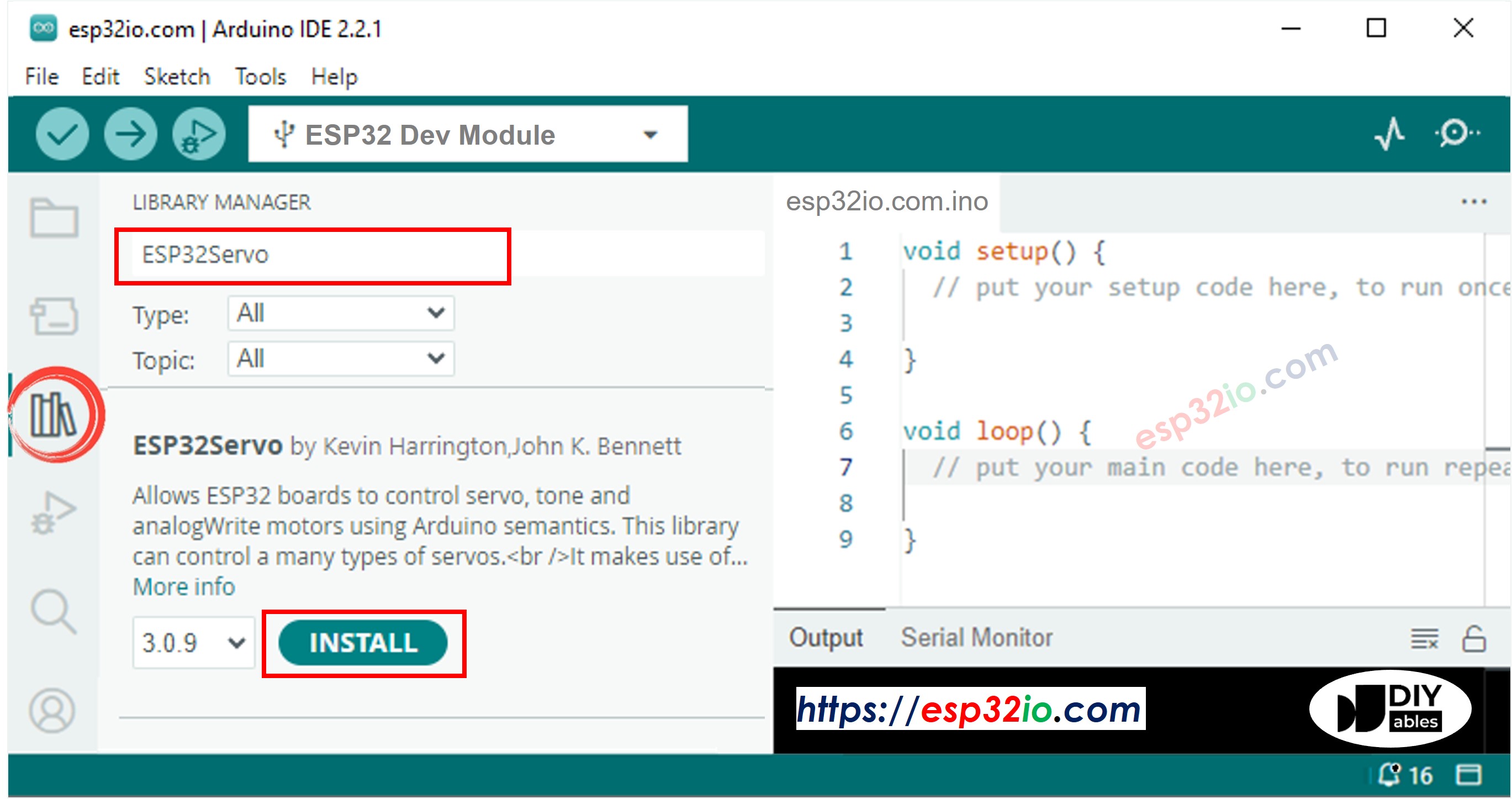
- Install ESP32Servo library: Click the Libraries icon on the left bar of the Arduino IDE. Type ESP32Servo in the search box, then look for the servo library by Kevin Harrington, John K. Bennett. Click Install to install the servo motor library for ESP32.
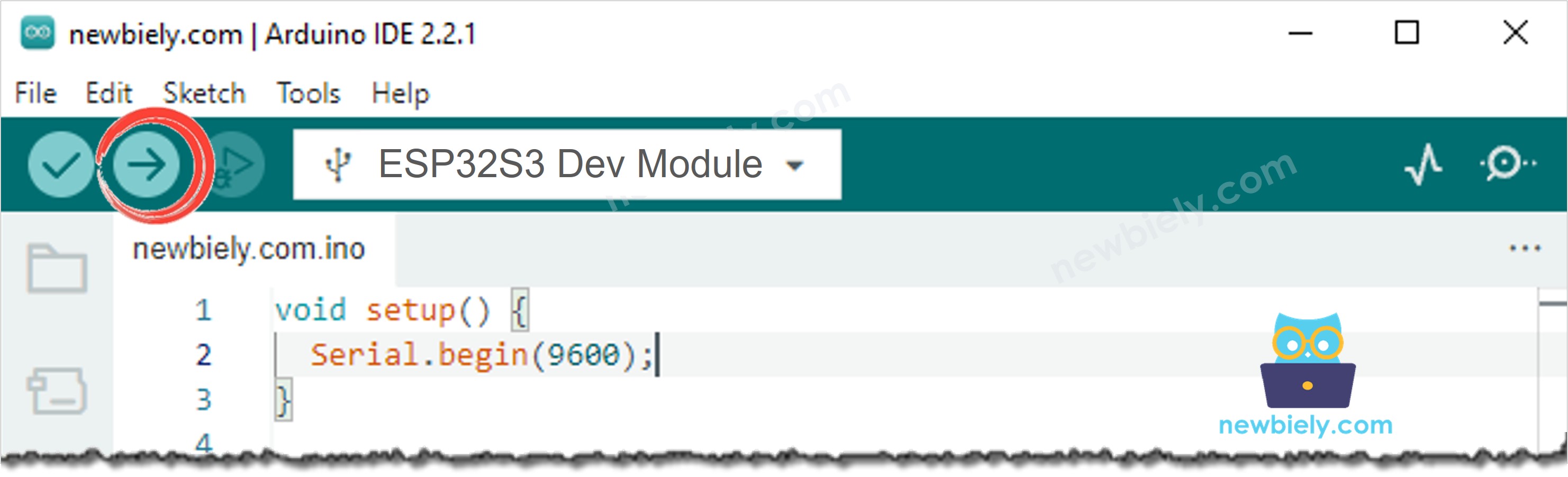
- Upload the code: Copy the code above and paste it into Arduino IDE, then click the Upload button.
- Open Serial Monitor: Open the Serial Monitor at 9600 baud to see live motion detection status and servo angle updates.
- Test the sensor: Move your hand in front of the motion sensor and observe the servo motor responding to detected motion.
- Pro Tip: If the servo twitches erratically after the sensor stops detecting motion, add a small capacitor (100–470 µF) across the servo's power rails to filter voltage spikes caused by the motor returning to 0°.
Serial Monitor Output
Open the Serial Monitor at 9600 baud after uploading. You will see output similar to the following as you move in front of the sensor:
Application Ideas
Combining the ESP32 S3 with a motion sensor and servo motor unlocks a broad set of presence-triggered actuation projects across home automation, security, and robotics. Here are some practical ideas to get you started:
- Automatic door or gate: Use the servo to swing a barrier open when a person is detected in the sensing area, then close it automatically once motion stops.
- Security camera pan trigger: Rotate a servo-mounted camera toward the detected motion zone to automatically frame any intruder or visitor.
- Presence-activated vent or damper: Open or close an air vent flap with the servo when people are present in a room, improving HVAC efficiency.
- Touchless access barrier: Lift a servo-driven arm to grant entry when someone approaches a restricted area, then lower it once they have passed.
- Pet feeder trigger: Rotate a servo-controlled dispensing wheel to release food when your pet approaches the feeding station.
- Alarm latch: Physically engage or disengage a servo-driven locking pin when motion is detected within a security perimeter.
Video Tutorial
Watch the step-by-step video walkthrough for this ESP32 S3 project below.
Challenge Yourself
Now that your ESP32 S3 motion-sensor-servo circuit is working, try these progressively harder challenges to deepen your understanding of PIR sensing and servo actuation:
- Beginner: Change the servo target angle in the code from 90° to 45° or 180° and observe how the servo responds differently to the same motion events.
- Beginner: Add a delay after motion stops before the servo returns to 0°, so the servo holds its position for a few seconds after the last detected movement.
- Intermediate: Add an LED indicator to the ESP32 S3 that lights up when motion is detected, providing a visual cue alongside the servo movement.
- Intermediate: Log motion events with a timestamp to the Serial Monitor, recording each time the sensor transitions from NOT DETECTED to DETECTED and back.
- Advanced: Add an OLED display to the ESP32 S3 that shows the current motion status and the number of motion events detected since power-on.
- Advanced: Build a multi-zone system using two HC-SR501 sensors covering different directions, each independently triggering its own servo when motion is detected in its zone.