
ESP32 S3 - Door Sensor - Servo Motor
This tutorial shows you how to use the ESP32 S3 with a magnetic door sensor and a servo motor to build an automatic position-control system that reacts to door open and close events. The ESP32 S3 continuously monitors the door sensor and rotates the servo to a target angle whenever the door state changes — making this a practical foundation for door-linked locking mechanisms, vent flaps, and flag indicators.
What you'll build:
- An ESP32 S3 circuit with a magnetic door sensor and servo motor wired to the board
- A sketch that reads the door sensor state and rotates the servo to 90 degrees when the door opens and back to 0 degrees when the door closes
- An automatic position-control loop that repeats every time the door state changes
- A foundation for real-world applications such as door-activated locking arms, ventilation flaps, and visual indicators
Hardware Preparation
Or you can buy the following kits:
| 1 | × | DIYables ESP32 S3 Starter Kit (ESP32 S3 included) | |
| 1 | × | DIYables Sensor Kit (18 sensors/displays) |
Additionally, some of these links are for products from our own brand, DIYables .
Buy Note: For controlling multiple servo motors, use the PCA9685 16 Channel PWM Servo Driver Module to save MCU pins and simplify wiring.
Overview of Servo Motor and Door Sensor
A magnetic door sensor consists of two parts — a reed switch body and a magnet — that together change circuit state when the door opens and the magnet moves away from the reed switch. The ESP32 S3 reads this digital state change on a GPIO input pin and responds by commanding a servo motor through a PWM signal on a second GPIO pin. The servo motor converts that PWM pulse width into a precise shaft angle, making it ideal for applications where a physical actuator must respond automatically to door events.
Key Specifications
We have dedicated tutorials covering each component in depth. Each tutorial contains detailed information and step-by-step instructions about hardware pinout, working principle, wiring connection to the ESP32 S3, and Arduino code. Learn more about them at the following links:
Wiring Diagram
Connect the door sensor and servo motor to your ESP32 S3 following the diagram below, and verify every connection before applying power to the board. The door sensor's signal wire connects to an ESP32 S3 GPIO configured as an input with the internal pull-up resistor enabled, while the servo's control signal wire connects to a GPIO configured for PWM output.
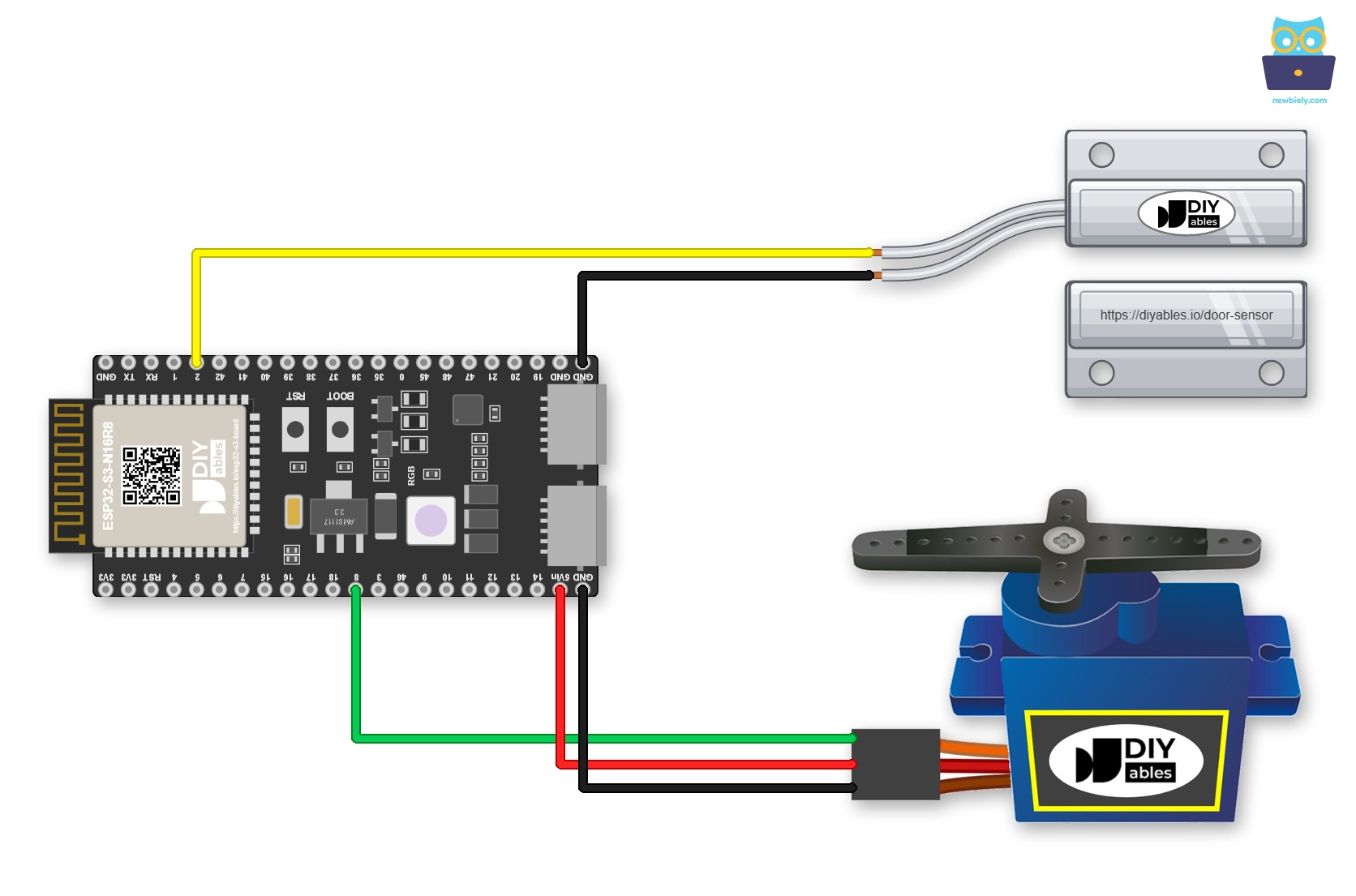
This image is created using Fritzing. Click to enlarge image
Module wires and thick wires often do not sit well in the female headers. Put the ESP32 S3 on a Screw Terminal Block for ESP32 S3, then tighten each wire under a screw. The diagram below shows the same wiring with the screw terminal board.
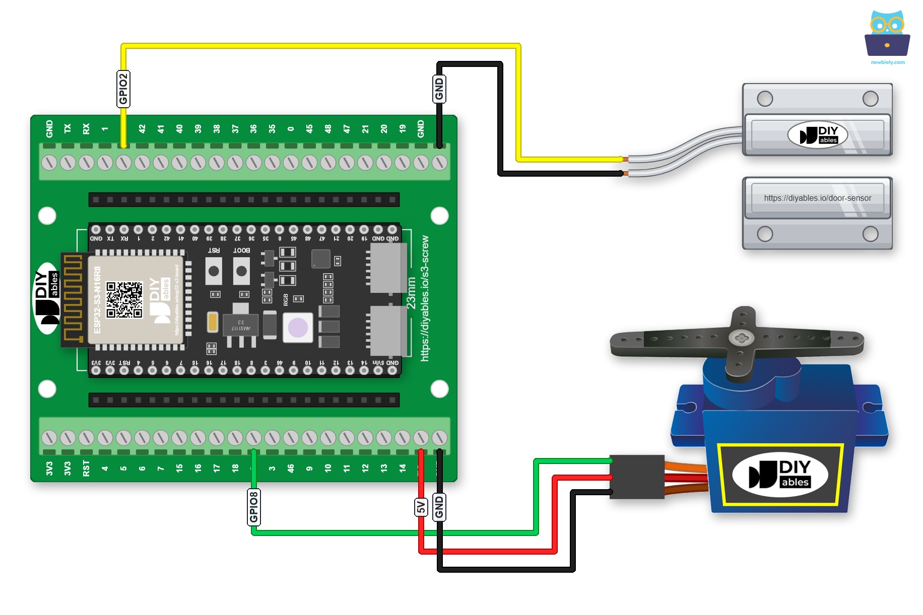
This image is created using Fritzing. Click to enlarge image
Or plug the ESP32 S3 into a GPIO Breakout Board for ESP32 S3. The same wiring then looks like this:
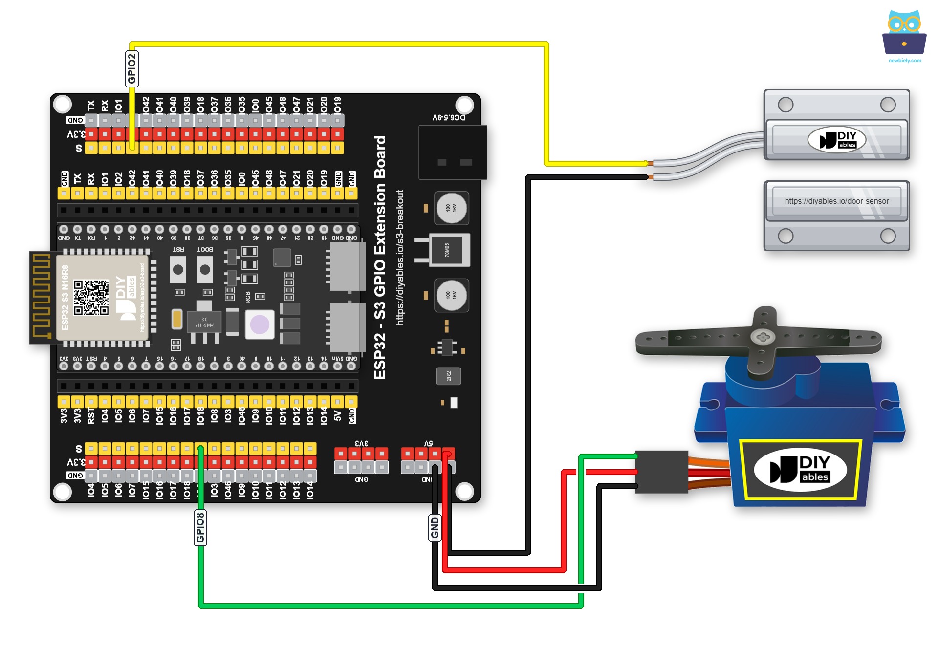
This image is created using Fritzing. Click to enlarge image
Safety Notes
The servo motor draws more current than a single ESP32 S3 GPIO pin can safely supply, so always power the servo from the board's 5V rail (or an external 5V supply) rather than from the GPIO pin itself. The ESP32 S3 GPIO pins operate at 3.3V logic, and most hobby servo motors accept a 3.3V control signal without issues, but check your specific servo's datasheet to confirm. The door sensor connects to a GPIO input with the internal pull-up resistor enabled, so no external pull-up resistor is required for the sensor side of the circuit.
| Component | Pin | ESP32 S3 Pin |
|---|---|---|
| Door Sensor | Wire 1 | GND |
| Door Sensor | Wire 2 | GPIO2 |
| Servo Motor | VCC (Red) | 5V |
| Servo Motor | GND (Brown/Black) | GND |
| Servo Motor | Signal (Orange/Yellow) | GPIO8 |
ESP32 S3 Code - Door Sensor Controls Servo Motor
The following code reads the door sensor state on every loop iteration and rotates the servo motor to 90 degrees when the door is detected as open, then rotates it back to 0 degrees when the door is detected as closed. The sketch relies on the ESP32Servo library to generate the correct PWM signal for the servo motor, so you must install that library before uploading.
Detailed Instructions
- New to ESP32 S3? Complete our Getting Started with ESP32 S3 guide first.
- Wire the door sensor and servo motor to the ESP32 S3 following the wiring diagram above.
- Connect the ESP32 S3 board to your PC using a USB Type-C cable.
- Open Arduino IDE on your PC.
- Select the correct ESP32 S3 board and COM port from the Tools menu.
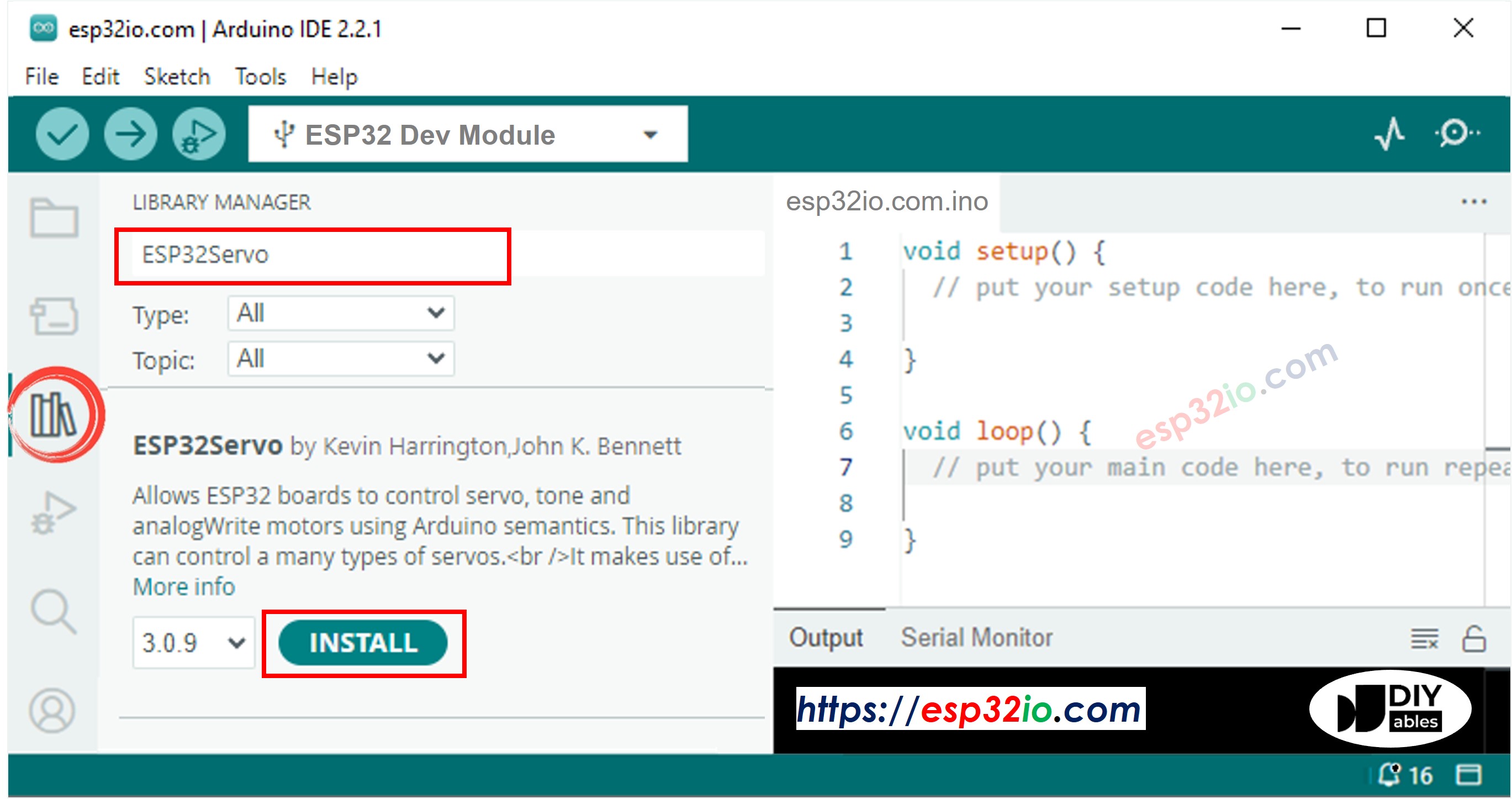
- Click the Libraries icon on the left bar of the Arduino IDE.
- Search for ESP32Servo in the search box, then locate the servo library by Kevin Harrington and John K. Bennett.
- Click Install to install the servo motor library for ESP32.
- Copy the above code and paste it into Arduino IDE.
- Click the Upload button to compile and upload the code to your ESP32 S3.
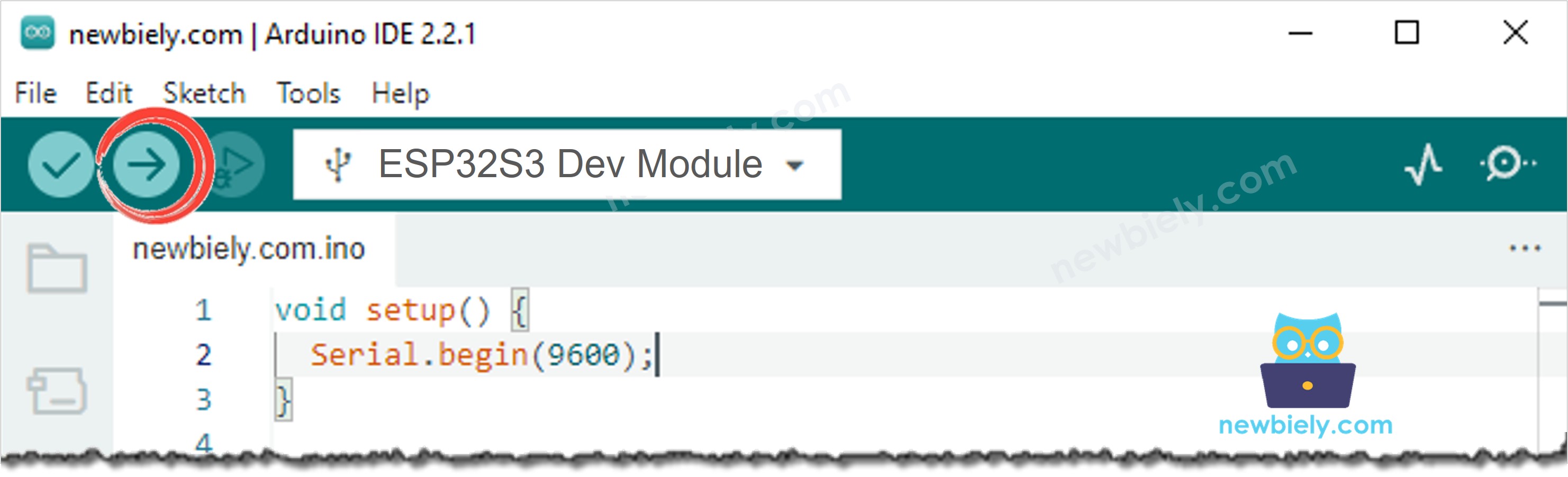
- Move the magnet close to the reed switch, then move it away to simulate opening the door.
- Watch the servo motor rotate to 90 degrees when the door opens and return to 0 degrees when the door closes.
- Pro Tip: If the servo motor twitches or behaves erratically, power it from an external 5V supply instead of the ESP32 S3 board's 5V pin, as high-current servos can cause voltage dips that reset the board.
Serial Monitor Output
Open the Arduino IDE Serial Monitor at 9600 baud to observe the door sensor state and servo motor position in real time.
Application and Project Ideas
Once the ESP32 S3 can automatically position a servo motor in response to door sensor events, you can adapt this project into a wide range of practical automation, security, and robotics applications.
- Door lock arm: Attach a physical locking arm to the servo so it rotates into a locked position when the door closes and retracts when the door opens.
- Vent flap controller: Use the servo to open a ventilation flap when a door opens, ensuring air circulation in enclosed spaces such as server rooms or storage areas.
- Flag or signal indicator: Rotate a small flag or colored indicator to the "open" position whenever the door is ajar, providing a visible status at a distance.
- Cabinet latch: Automatically latch a cabinet door closed using the servo each time the door sensor detects the door in the closed position.
- Multi-door coordinator: Monitor two door sensors and map their combined states to four servo positions, implementing a simple interlocking mechanism between two adjacent doors.
- Event-triggered camera tilt: Mount a camera on the servo shaft so the lens automatically points toward the doorway whenever the door sensor detects an opening, capturing whoever enters.
Video Tutorial
Watch the step-by-step video walkthrough for this ESP32 S3 project below.
Challenge Yourself
Now that you can automatically control a servo motor with a door sensor on the ESP32 S3, try these progressively harder challenges to deepen your understanding and build a more capable system.
- Beginner: Change the target servo angle from 90 degrees to 45 degrees by modifying a single constant in the sketch, then re-upload and verify the new position.
- Beginner: Add a Serial Monitor counter that increments and prints the total number of door-open events since the board was powered on.
- Intermediate: Use millis() instead of delay() to implement a time-delayed servo return — the servo moves to 90 degrees when the door opens but returns to 0 degrees only after 5 seconds, regardless of when the door closes.
- Intermediate: Add a second servo motor to the circuit and drive both servos simultaneously but in opposite directions, one opening as the other closes.
- Advanced: Combine the door sensor and servo with an RFID reader so the servo only rotates (unlocks) after a valid RFID card is scanned, while the door sensor provides confirmation that the door has actually been opened.
- Advanced: Connect the ESP32 S3 to Wi-Fi and publish the door state and servo position to an MQTT broker each time a transition occurs, enabling remote monitoring through a home automation dashboard.