
ESP32 S3 - Keypad - Electromagnetic Lock
Learning how to combine a keypad, relay, and electromagnetic lock with the ESP32 S3 is an excellent way to build real-world access control systems. This tutorial shows you how to read a password from a 3x4 keypad and use it to control an electromagnetic lock through a relay — including a timed-unlock variant that releases the door for a fixed period without blocking code execution.
What you'll build:
- A circuit connecting a 3x4 keypad and an electromagnetic lock (via relay) to the ESP32 S3
- Code that checks the entered password and unlocks the door if it matches one of the pre-defined codes
- An extended version that keeps the door unlocked for 5 seconds and then re-locks automatically
- Serial Monitor output showing whether each password attempt succeeded or failed
https://newbiely.com/images/cover/esp32-s3-keypad-electromagnetic-lock.jpg
Hardware Preparation
Or you can buy the following kits:
| 1 | × | DIYables ESP32 S3 Starter Kit (ESP32 S3 included) | |
| 1 | × | DIYables Sensor Kit (18 sensors/displays) |
Additionally, some of these links are for products from our own brand, DIYables .
Overview of Keypad and Electromagnetic Lock
A 3x4 matrix keypad lets users enter numeric codes using a compact 12-key layout, while an electromagnetic lock (maglock) uses magnetic force to hold a door closed whenever power is applied. Together with a relay that switches the lock's 12V supply, these components form a complete password-controlled access system that the ESP32 S3 can manage entirely in software.
Key Specifications
Unfamiliar with the keypad or electromagnetic lock and how to wire and program them individually? Review the dedicated tutorials below before proceeding:
- ESP32 S3 - Keypad tutorial
- ESP32 S3 - Electromagnetic Lock tutorial
Wiring Diagram
Connect the 3x4 keypad row and column pins to available GPIO pins on the ESP32 S3, then wire the relay signal pin to a separate GPIO. The electromagnetic lock connects to the relay's normally-open contacts and is powered by the 12V adapter, keeping the high-voltage lock circuit isolated from the ESP32 S3 logic.
Safety Notes
The electromagnetic lock operates at 12V and draws significant current when energised — always use the relay to switch the lock supply and never connect the lock wires directly to any ESP32 S3 GPIO pin. Ensure the 12V adapter is rated for at least the current draw listed on your electromagnetic lock, and verify that all high-voltage wiring is fully insulated before powering the system.
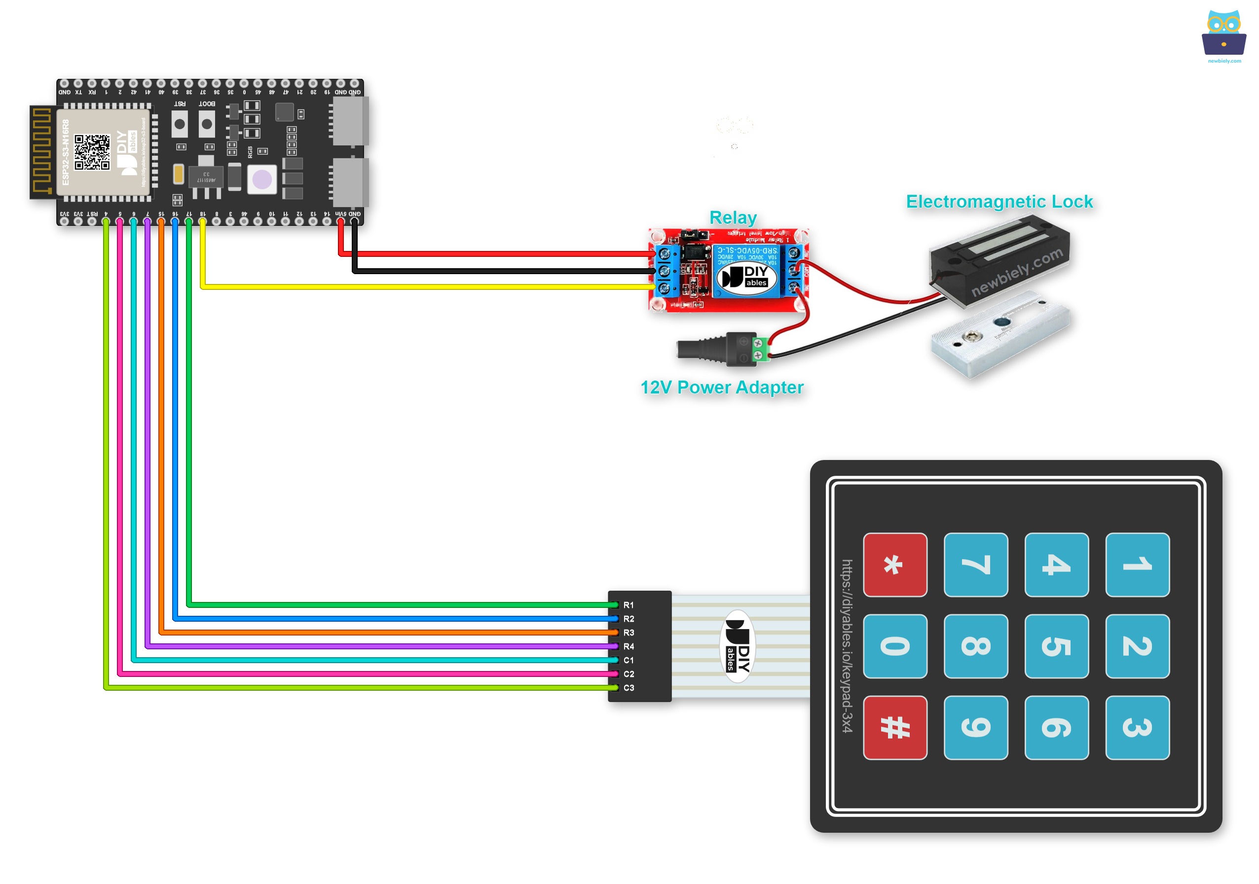
This image is created using Fritzing. Click to enlarge image
| Component Pin | ESP32 S3 Pin | Notes |
|---|---|---|
| Keypad Row 1 | GPIO17 | First row of the 3x4 keypad |
| Keypad Row 2 | GPIO16 | Second row |
| Keypad Row 3 | GPIO15 | Third row |
| Keypad Row 4 | GPIO7 | Fourth row |
| Keypad Col 1 | GPIO6 | First column |
| Keypad Col 2 | GPIO5 | Second column |
| Keypad Col 3 | GPIO4 | Third column |
| Relay Signal (IN) | GPIO18 | Controls relay on/off |
| Relay VCC | 5V | Powers the relay module |
| Relay GND | GND | Common ground |
| Relay COM | 12V Power + | From power adapter |
| Relay NO | EM Lock Wire 1 | Normally open connection |
| EM Lock Wire 2 | 12V Power - | Completes the circuit |
Want a stronger connection than jumper wires? Put the ESP32 S3 on a Screw Terminal Block for ESP32 S3, then tighten each wire under a screw. This is how it looks with the screw terminal board:
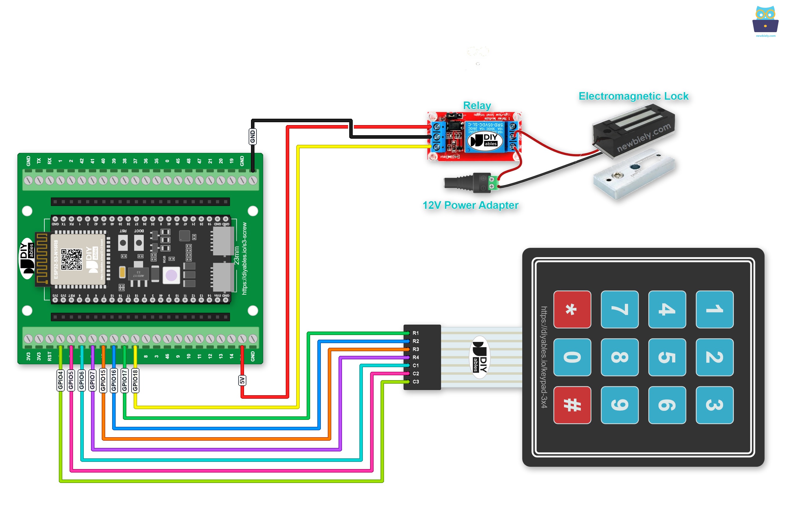
This image is created using Fritzing. Click to enlarge image
Or plug the ESP32 S3 into a GPIO Breakout Board for ESP32 S3. The same wiring then looks like this:
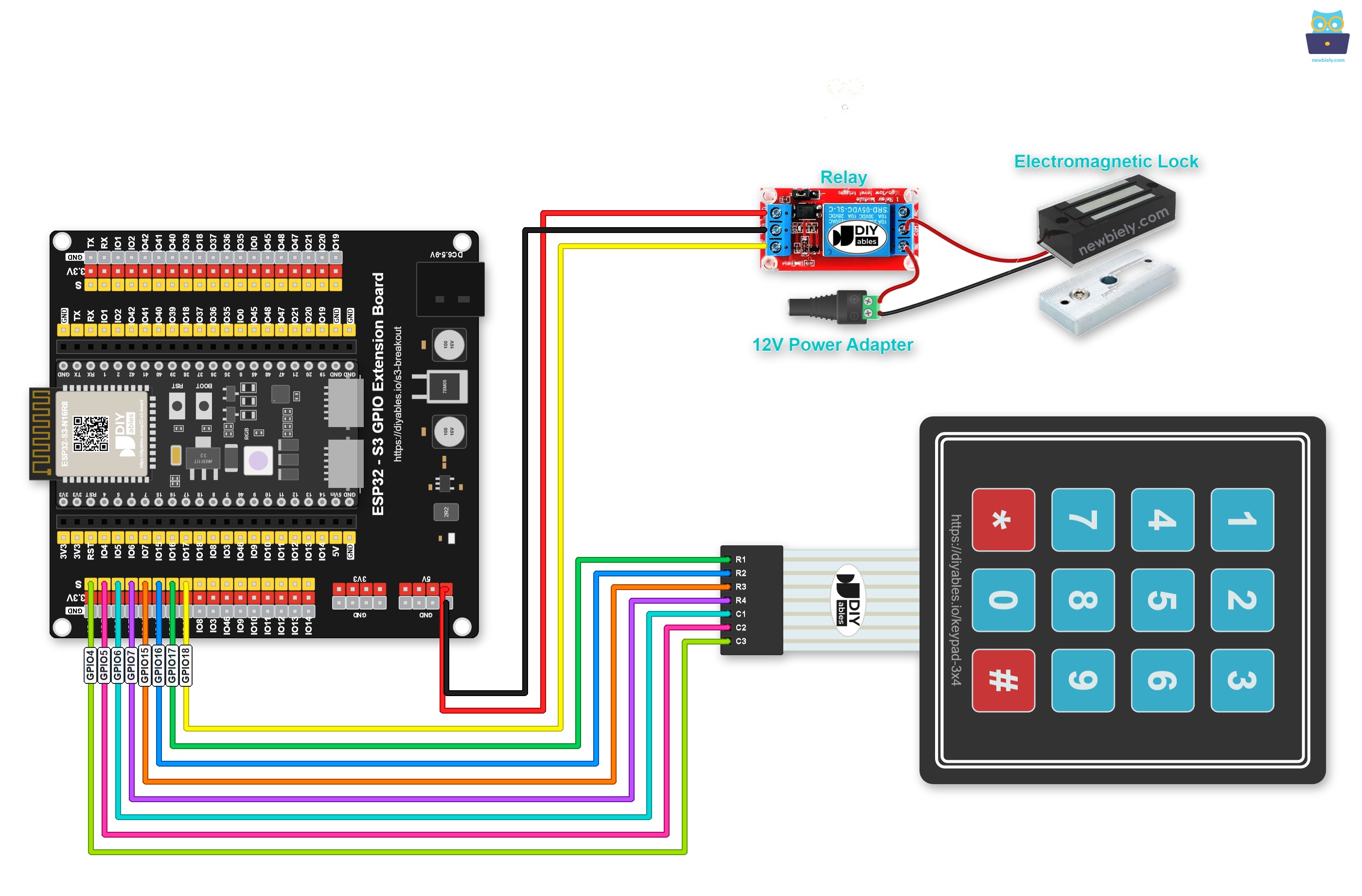
This image is created using Fritzing. Click to enlarge image
ESP32 S3 Code - Turn Electromagnetic Lock On If the Password Is Correct
The following code unlocks the electromagnetic lock when the user enters a correct password on the keypad and presses the # key. It pre-defines a list of valid passwords, accumulates key presses into an input string, clears that string when * is pressed, and compares the completed entry against each stored password when # is pressed — activating the relay if a match is found and printing the result to the Serial Monitor.
Detailed Instructions
- New to ESP32 S3? Complete our Getting Started with ESP32 S3 guide first.
- Wire the keypad, relay, and electromagnetic lock to the ESP32 S3 according to the wiring diagram above.
- Connect the ESP32 S3 to your computer using a USB Type-C cable.
- Open the Arduino IDE on your computer.
- Select your board: choose the correct ESP32 S3 board from Tools > Board menu.
- Choose your port: select the correct COM port from Tools > Port menu.
- Click the Libraries icon on the left sidebar of the Arduino IDE.
- Search "keypad", then find the keypad library by DIYables.
- Click Install button to install the keypad library.
- Search for DIYables_Keypad created by DIYables.io and click the Install button.
- Copy the above code and paste it into the Arduino IDE.
- Click Upload button on Arduino IDE to upload code to ESP32 S3.
- Press 8123 keys and press #.
- Press 1234 keys and press #.
- Check the Serial Monitor and observe the state of the electromagnetic lock.
- Pro Tip: Press * at any time to clear the current input and start over — useful if you make a typing mistake mid-password.
Serial Monitor Output
Open the Serial Monitor at 115200 baud after uploading and enter passwords on the keypad. You will see status messages similar to the following output:
Code Explanation
Authorized passwords are pre-defined in the ESP32 S3 code. A string is used to store the password entered by the user, called the input string. Two keys on the keypad (* and #) serve special purposes — clearing the input and finalising the entry. When a key is pressed:
- If the pressed key is not one of the two special keys, it is appended to the input string.
- If the pressed key is *, the input string is cleared so the user can start or restart entry.
- If the pressed key is #:
- The input string is compared against all pre-defined passwords. If it matches one of them, the electromagnetic lock is turned on.
- Regardless of whether the password is correct or not, the input string is cleared for the next attempt.
ESP32 S3 Code - Turn the Electromagnetic Lock On for a Period of Time If the Password Is Correct
The following code extends the basic example by unlocking the electromagnetic lock for 5 seconds when the correct password is entered and then re-locking automatically. It uses the ezOutput library to manage the timed output in a non-blocking manner, so the keypad continues to respond during the unlock period.
Please note that the above code uses the ezOutput library, which makes it easy to manage timed outputs without blocking code execution. You can refer to ezOutput Library Installation Guide for installation instructions.
Real-World Applications
Combining a keypad, relay, and electromagnetic lock with the ESP32 S3 opens the door to a wide variety of security and automation applications, from simple prototypes to production-grade access control systems.
- Residential Door Lock: Replace a traditional key lock with a PIN-based entry system on a front or back door.
- Office Access Control: Restrict entry to specific rooms or areas using employee-assigned PINs with optional event logging.
- Lab or Tutorial Security: Prevent unauthorised access to sensitive equipment or materials using a code-secured maglock.
- Storage Cabinet: Secure a filing cabinet or tool locker electronically using a smaller relay and lock combination.
- Multi-User Access: Store multiple valid passwords in the sketch so different users can each have their own unique PIN.
- IoT-Enhanced Security: Extend the system with ESP32 S3 Wi-Fi to allow remote unlock or send alerts when an incorrect password is entered repeatedly.
Video Tutorial
Watch the step-by-step video walkthrough for this ESP32 S3 project below.
Challenge Yourself
Now that you have a working keypad-controlled electromagnetic lock on the ESP32 S3, try these progressively challenging extensions to build deeper access control skills.
- Beginner: Change one of the pre-defined passwords in the code and confirm the new code works and the old one no longer does.
- Beginner: Add an LED indicator that lights up green for a correct password and red for an incorrect one.
- Intermediate: Add a piezo buzzer that plays a short success melody on correct entry and a different tone on failure.
- Intermediate: Implement a lockout that disables keypad input for 60 seconds after three consecutive incorrect attempts.
- Advanced: Store the password list in NVS flash so it persists across power cycles and add an admin code that lets the user update passwords at runtime.
- Advanced: Integrate an RFID reader so the door can be unlocked with either a keypad PIN or an RFID card.