
ESP32 S3 - Door Sensor Toggle Relay
This tutorial shows you how to use the ESP32 S3 with a magnetic door sensor to toggle a relay's state each time the door is closed. Every time the door closes and the magnet approaches the reed switch, the relay switches to its opposite state — a versatile pattern for building sensor-driven automation circuits.
What you'll build:
- An ESP32 S3 circuit with a door sensor and relay wired to the board
- A sketch that toggles the relay state each time the door is closed
- Serial Monitor output confirming each toggle event in real time
- A reusable pattern for controlling high-voltage devices such as lamps, fans, and solenoids via door events
https://newbiely.com/images/cover/esp32-s3-door-sensor-relay.jpg
We can extend this tutorial to use the door sensor to control an LED strip, siren, light bulb, or actuator by connecting them to the relay.
Hardware Preparation
Or you can buy the following kits:
| 1 | × | DIYables ESP32 S3 Starter Kit (ESP32 S3 included) | |
| 1 | × | DIYables Sensor Kit (18 sensors/displays) |
Additionally, some of these links are for products from our own brand, DIYables .
Overview of Relay and Door Sensor
A relay and a magnetic door sensor are two highly complementary components for ESP32 S3 automation projects. The door sensor provides a clean digital signal whenever the door transitions between open and closed states, while the relay acts as an electrically isolated switch capable of safely controlling high-voltage or high-current loads far beyond what the ESP32 S3's GPIO pins can drive directly. Together they make it straightforward to automate real-world devices in response to physical entry events.
Key Specifications
For detailed coverage of each component, visit the dedicated tutorials linked below:
- ESP32 S3 - Relay tutorial - Learn relay basics, pinout, and wiring
- ESP32 S3 - Door Sensor tutorial - Understand door sensor reading and pull-up configuration
Wiring Diagram
Connect the door sensor reed switch and relay module to your ESP32 S3 by following the diagram below. Verify every connection before applying power, paying particular attention to the relay's high-voltage output terminals.
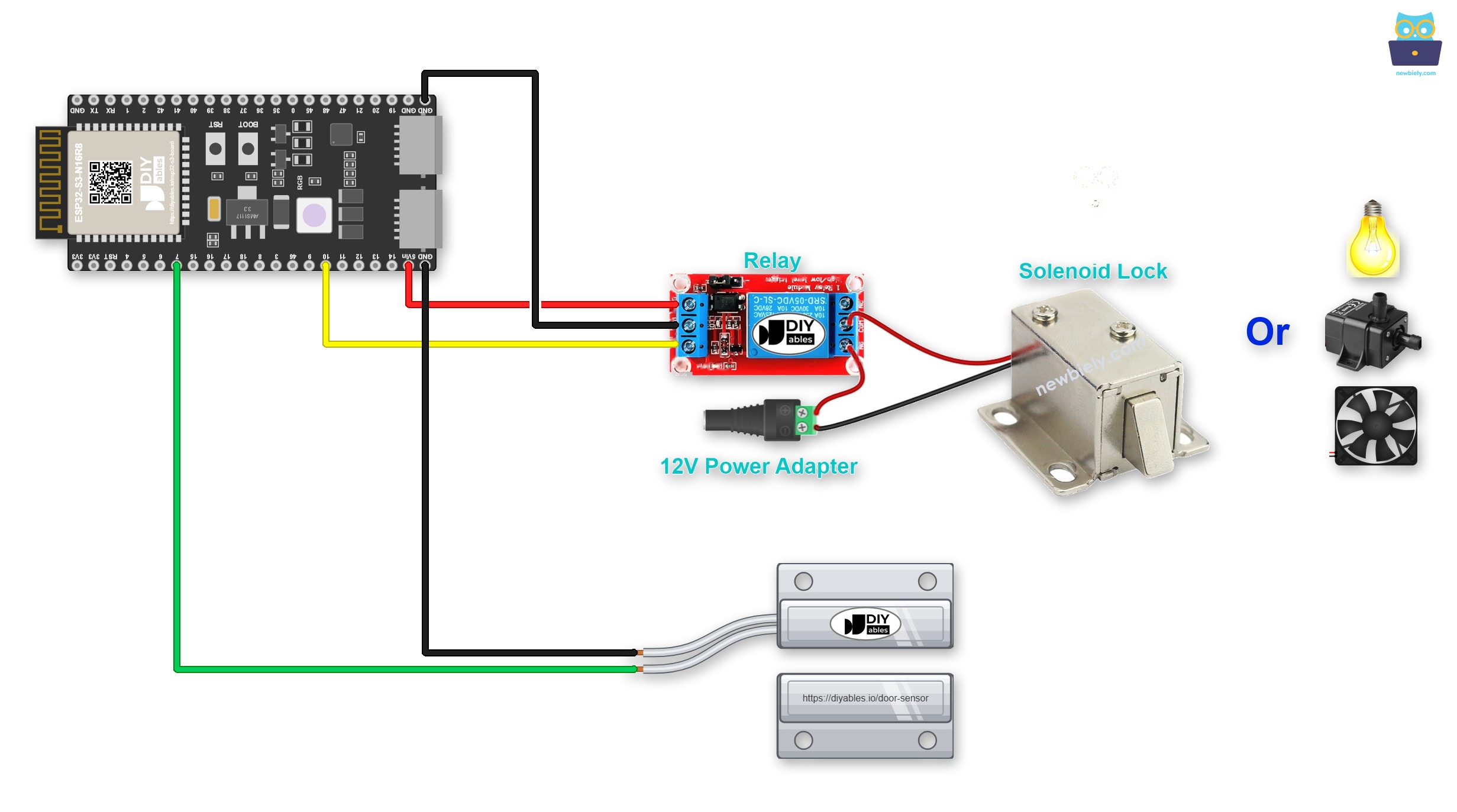
This image is created using Fritzing. Click to enlarge image
Do you want the wiring to stay in place? A Screw Terminal Block for ESP32 S3 solves this. Plug the ESP32 S3 into it and screw the wires in. See the diagram below for the screw terminal version.
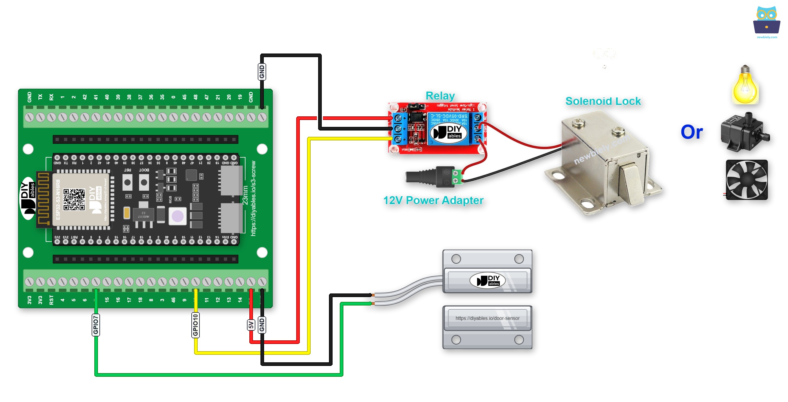
This image is created using Fritzing. Click to enlarge image
Another choice is a GPIO Breakout Board for ESP32 S3. Each GPIO has a signal pin with 3.3V and GND pins next to it, as shown below:
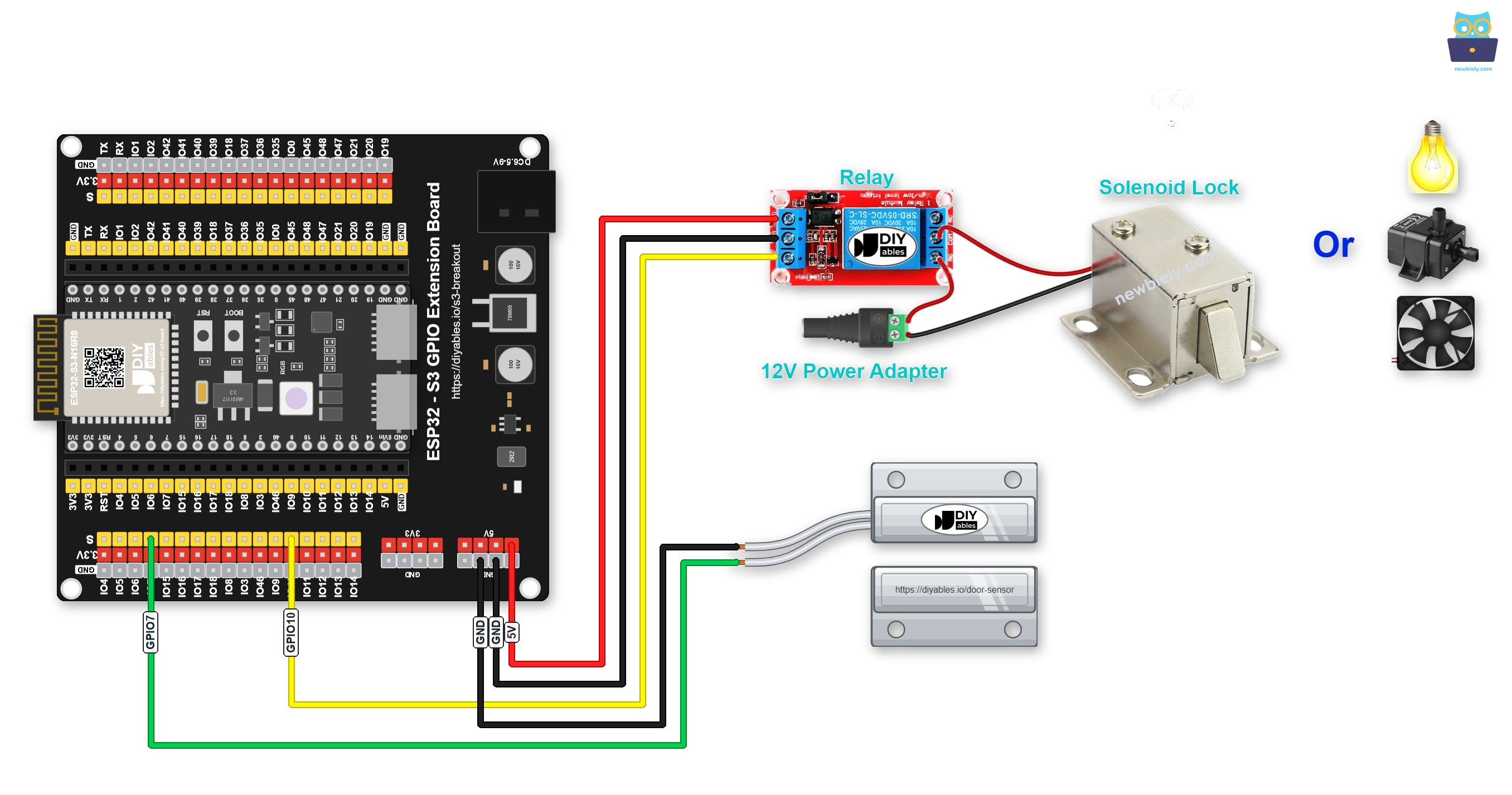
This image is created using Fritzing. Click to enlarge image
Safety Notes
The relay's COM, NO, and NC terminals connect to the high-voltage side of your circuit. Keep all mains-voltage wiring physically separated from the low-voltage control wiring, and ensure bare conductors are fully insulated before powering the circuit. If you are unsure about high-voltage wiring, use a low-voltage DC load such as a 12 V LED strip or solenoid for initial testing before connecting mains equipment.
| Component | Pin | ESP32 S3 Pin |
|---|---|---|
| Door Sensor | Wire 1 (reed switch) | GND |
| Door Sensor | Wire 2 (reed switch) | GPIO7 |
| Relay | DC- | GND |
| Relay | DC+ | 5V |
| Relay | IN | GPIO10 |
ESP32 S3 Code - Door Sensor Toggles Relay
The following code reads the door sensor reed switch on every loop iteration, detects a door-closing event (a HIGH-to-LOW transition on the input pin), and inverts the relay output variable before writing the new state to the relay pin. No external library is required — the logic relies entirely on built-in Arduino functions and the ESP32 S3's internal pull-up resistor.
Detailed Instructions
- New to ESP32 S3? Complete our Getting Started with ESP32 S3 guide first.
- Wire the components following the wiring diagram shown above.
- Connect the ESP32 S3 to your computer using a USB Type-C cable.
- Open Arduino IDE and select the correct ESP32 S3 board and COM port.
- Copy the code above and paste it into Arduino IDE.
- Click the Upload button to compile and upload the sketch to the ESP32 S3.
- Move the magnet close to the reed switch and then move it far away. Repeat this several times.
- Observe the relay state change each time the door closes (magnet approaches the reed switch).
- Pro Tip: If the relay toggles more than once per door-close event, check for a loose or vibrating magnetic connection — even small magnet movements can produce multiple transitions if the reed switch contacts are on the edge of their activation range.
Line-by-line Code Explanation
The above ESP32 S3 code contains line-by-line explanation in the comments. Please read those comments carefully!
In the code, relayState = !relayState is equivalent to the following code:
Serial Monitor Output
Open the Serial Monitor at 115200 baud after uploading to observe the relay toggle events triggered by door-closing in real time. The output below shows what you should expect when the door is opened and closed several times.
Application and Project Ideas
Once you master door-sensor-toggled relay control with the ESP32 S3, you can apply this pattern to a wide range of practical security and home automation projects.
- Automated room light: Toggle a relay-controlled ceiling light on whenever the bedroom door is closed and off when opened.
- Entry buzzer: Trigger a relay-powered siren or buzzer each time a door is closed to alert occupants of entry events.
- Refrigerator energy guard: Toggle a relay to cut power to a secondary fridge if the door has been closed more than a threshold number of times in a short period.
- Solenoid lock controller: Toggle a solenoid lock between locked and unlocked states with each door-close event for a keyless entry system.
- Tutorial ventilation: Automatically toggle a 12 V cooling fan each time a tutorial cabinet door closes to maintain airflow around heat-generating equipment.
- Security alarm: Toggle a 12 V warning light whenever the door is closed after business hours to signal unauthorized access.
Video Tutorial
Watch the step-by-step video walkthrough for this ESP32 S3 project below.
Challenge Yourself
Now that you can toggle a relay with a door sensor on the ESP32 S3, try these progressively more demanding extensions to deepen your understanding of sensor-driven automation.
- Beginner: Modify the sketch to print the relay's current state (ON or OFF) to the Serial Monitor every time a door-closing event is detected.
- Beginner: Add an LED indicator wired in parallel with the relay IN pin so you get visual feedback of the relay state without needing a Serial Monitor.
- Intermediate: Add a counter that tracks the total number of relay toggles since power-on and prints it to the Serial Monitor alongside each toggle event.
- Intermediate: Implement a timed relay — the relay turns ON when the door closes but automatically turns OFF after 30 seconds, regardless of subsequent door events.
- Advanced: Build a Wi-Fi-enabled version using the ESP32 S3's wireless interface so you can monitor relay state and door events from a browser in real time.
- Advanced: Log each toggle event with a timestamp and the new relay state to an SD card so you have a persistent record of door activity over time.