ESP32 S3 - Joystick - Servo Motor

In this tutorial, you will learn how to use the ESP32 S3 board with a joystick to control two servo motors or a pan-tilt kit. By reading the joystick's analog X and Y axis values, you can precisely drive each servo motor independently for intuitive directional control.

A joystick has two built-in potentiometers arranged at right angles (called X-axis and Y-axis), which output analog values on the VRX and VRY pins. You will use these analog values to control two servo motors independently: the X-value controls servo #1 and the Y-value controls servo #2. When used with a pan-tilt kit, the combined movement of the two servo motors creates smooth 3D motion.

What you'll build:

  1. A joystick-controlled dual servo system using the ESP32 S3
  2. Use case 1: Servo motors rotate proportionally to the joystick thumb position and return to center on release
  3. Use case 2: Joystick commands servo motors step-by-step in four directions with a button to reset center
  4. Optional pan-tilt kit integration for 3D camera or sensor positioning

Hardware Preparation

1×ESP32 S3 WROOM N16R8
1×Alternatively, ESP32 S3 SuperMini Dev Module
1×Alternatively, ESP32 S3 Uno-form Board
1×Alternatively, ESP32 S3 Camera Board
1×USB Cable Type-A to Type-C (for USB-A PC)
1×USB Cable Type-C to Type-C (for USB-C PC)
1×Joystick
2×Servo Motor
2×Optionally, Pan-tilt kit with servo motor
1×Breadboard
1×Jumper Wires
1×Optionally, DC Power Jack
1×Recommended: Screw Terminal Expansion Board for ESP32 S3
1×Recommended: Breakout Expansion Board for ESP32 S3
1×Recommended: Power Splitter for ESP32 S3

Or you can buy the following kits:

1×DIYables ESP32 S3 Starter Kit (ESP32 S3 included)
1×DIYables Sensor Kit (18 sensors/displays)
Disclosure: Some of the links provided in this section are Amazon affiliate links. We may receive a commission for any purchases made through these links at no additional cost to you.
Additionally, some of these links are for products from our own brand, DIYables .

Buy Note: For controlling multiple servo motors, use the PCA9685 16 Channel PWM Servo Driver Module to save MCU pins and simplify wiring.

Overview of Joystick and Servo Motor

The joystick and servo motor are fundamental components for building motion-control projects with the ESP32 S3. Understanding how each component works individually will help you combine them effectively in this tutorial.

Key Specifications

Wiring Diagram

Connect the joystick's VRX and VRY pins to two ADC-capable GPIO pins on the ESP32 S3, and connect each servo motor's signal wire to separate PWM-capable GPIO pins. Ensure the servo motors are powered with an adequate 5V supply, using an external power source if multiple servos are connected.

Safety Notes

Servo motors can draw significant current, especially under load. Always power multiple servo motors from an external 5V supply rather than the ESP32 S3's onboard 3.3V regulator to avoid damaging the board.
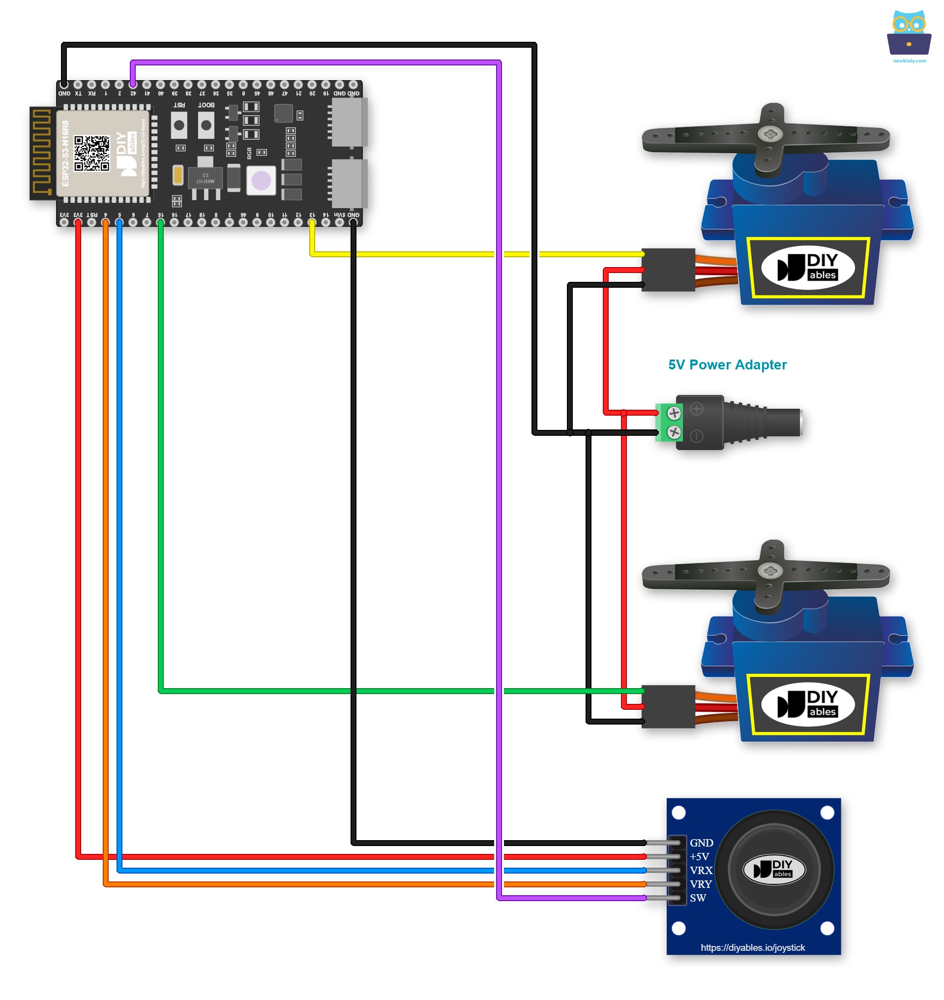
The wiring diagram between ESP32 S3 Joystick Servo Motor

This image is created using Fritzing. Click to enlarge image

If you plan to keep this circuit, think about screw terminals. Put the ESP32 S3 on a Screw Terminal Block for ESP32 S3, then tighten each wire under a screw. See the diagram below for the screw terminal version.
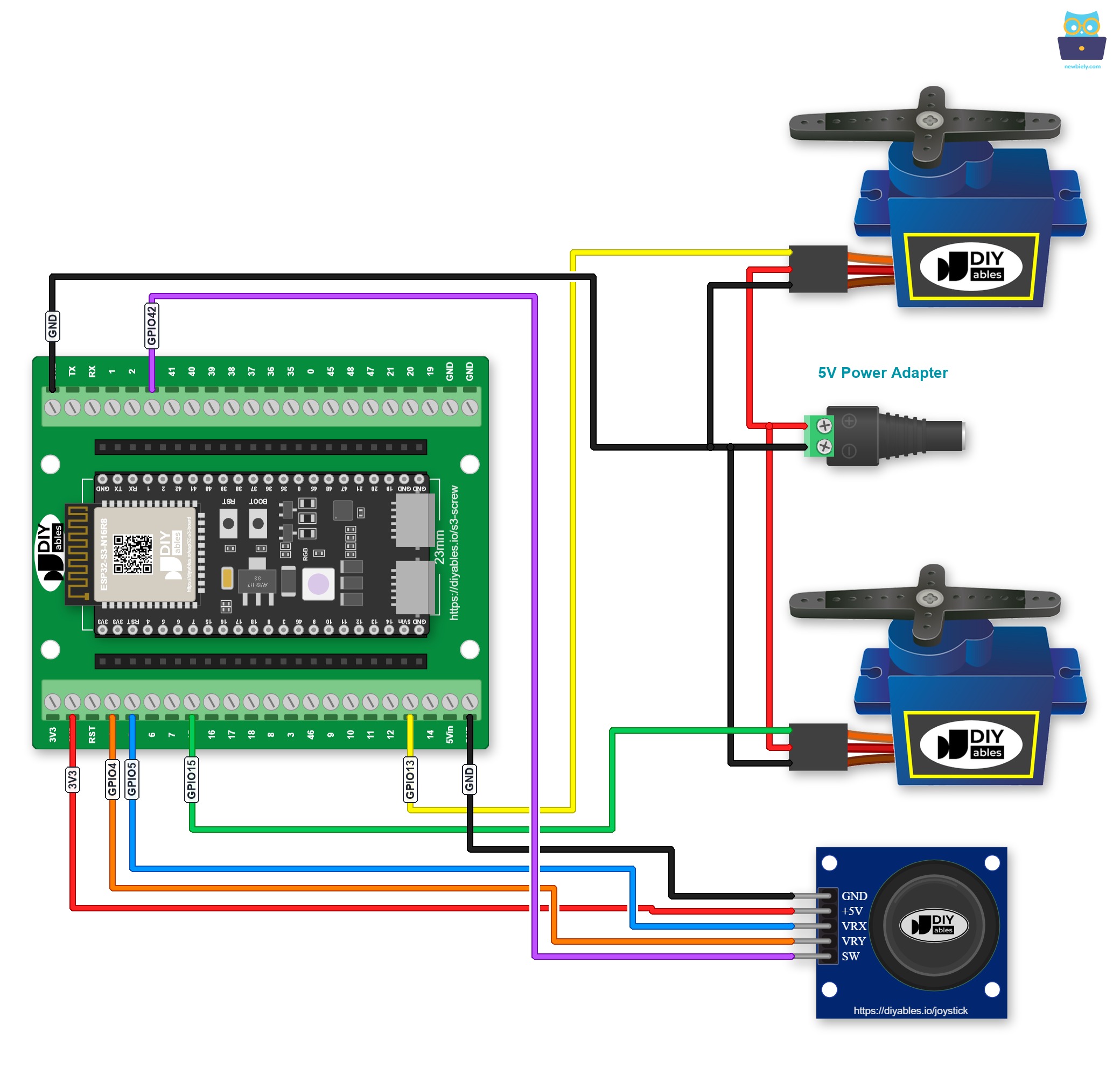
The wiring diagram between ESP32 S3 Joystick Servo Motor Screw Terminal

This image is created using Fritzing. Click to enlarge image

Prefer pin headers to screws? Plug the ESP32 S3 into a GPIO Breakout Board for ESP32 S3 instead:
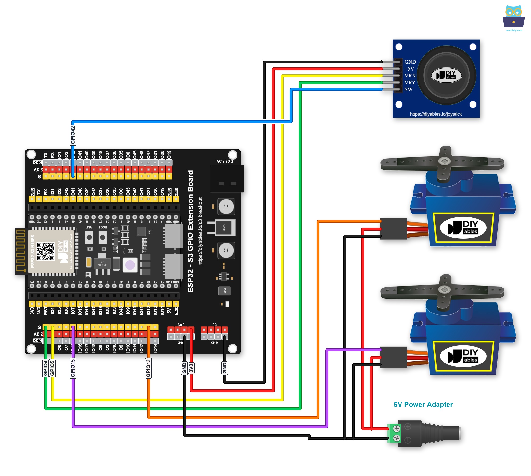
The wiring diagram between ESP32 S3 Joystick Servo Motor GPIO Breakout Board

This image is created using Fritzing. Click to enlarge image

ESP32 S3 Code

ESP32 S3 Code - The servo motors rotate according to the movement of the joystick's thumb

The following code reads the joystick's X and Y analog values and maps them directly to servo motor angles, so each servo tracks the joystick position in real time. When the thumb is released and returns to center, both servo motors automatically return to the 90-degree center position as well.

/* * This ESP32 S3 code was developed by newbiely.com * * This ESP32 S3 code is made available for public use without any restriction * * For comprehensive instructions and wiring diagrams, please visit: * https://newbiely.com/tutorials/esp32-s3/esp32-s3-joystick-servo-motor */ /* * This ESP32-S3 code is created by esp32io.com * * This ESP32-S3 code is released in the public domain * * For more detail (instruction and wiring diagram), visit https://esp32io.com/tutorials/esp32-s3-joystick-servo-motor */ #include <ESP32Servo.h> #define VRX_PIN 5 // ESP32-S3 pin GPIO5 (ADC1) connected to VRX pin #define VRY_PIN 4 // ESP32-S3 pin GPIO4 (ADC1) connected to VRY pin #define SERVO_X_PIN 13 // ESP32-S3 pin GPIO13 connected to Servo motor 1 #define SERVO_Y_PIN 15 // ESP32-S3 pin GPIO15 connected to Servo motor 2 Servo xServo; // create servo object to control a servo 1 Servo yServo; // create servo object to control a servo 2 void setup() { Serial.begin(9600); // Set the ADC attenuation to 11 dB (up to ~3.3V input) analogSetAttenuation(ADC_11db); xServo.attach(SERVO_X_PIN); yServo.attach(SERVO_Y_PIN); } void loop() { // read X and Y analog values int valueX = analogRead(VRX_PIN); int valueY = analogRead(VRY_PIN); int xAngle = map(valueX, 0, 4095, 0, 180); // scale it to the servo's angle (0 to 180) int yAngle = map(valueY, 0, 4095, 0, 180); // scale it to the servo's angle (0 to 180) xServo.write(xAngle); // rotate servo motor 1 yServo.write(yAngle); // rotate servo motor 2 // print data to Serial Monitor on Arduino IDE Serial.print("Joystick: "); Serial.print(valueX); Serial.print(", "); Serial.print(valueY); Serial.print(" => Servo Motor: "); Serial.print(xAngle); Serial.print("°, "); Serial.print(yAngle); Serial.println("°"); }

Detailed Instructions

  1. New to ESP32 S3? Complete our Getting Started with ESP32 S3 guide first.
  2. Connect the joystick and servo motors to the ESP32 S3 board as shown in the wiring diagram above.
  3. Connect the ESP32 S3 board to your PC via a USB Type-C cable.
  4. Open Arduino IDE on your PC.
  5. Select the right ESP32 S3 board and COM port.
  6. Click the Libraries icon on the left bar of the Arduino IDE.
  7. Type ESP32Servo in the search box, then look for the servo library by Kevin Harrington, John K. Bennett.
  8. Click Install button to install the servo motor library for ESP32.
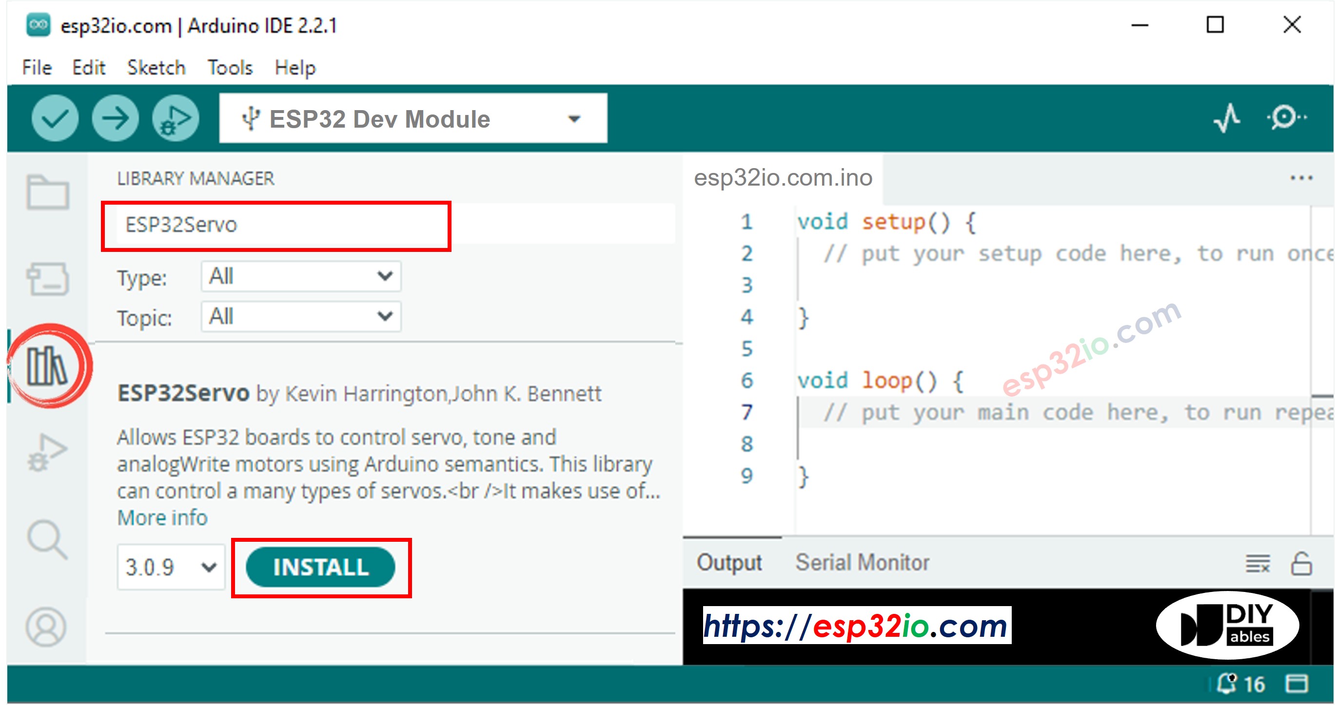
ESP32 S3 servo motor library
  1. Copy the above code and open it with Arduino IDE.
  2. Click Upload button on Arduino IDE to upload the code to ESP32 S3.
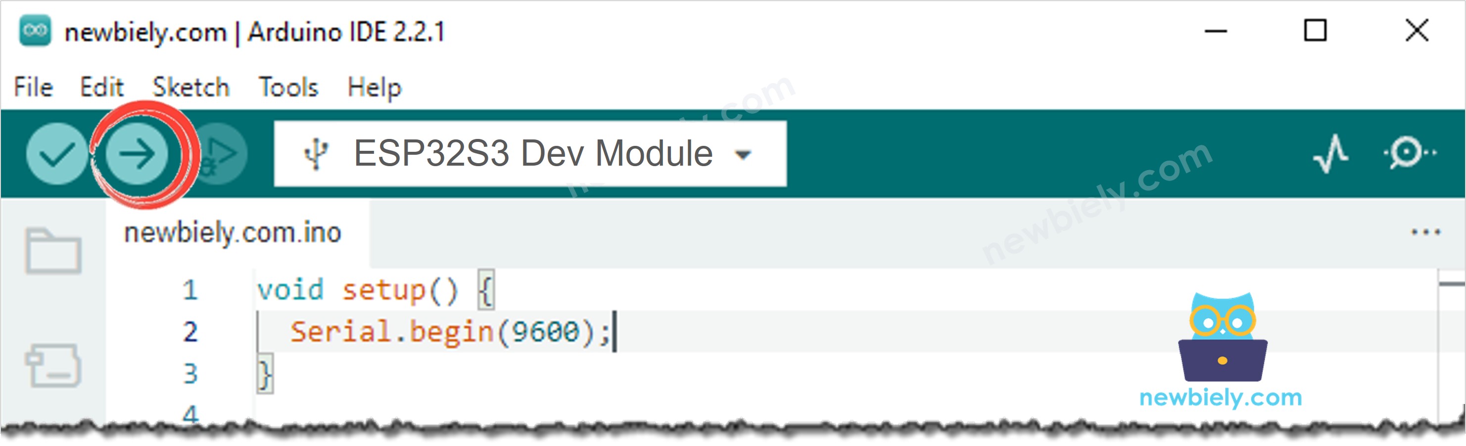
Arduino IDE Upload Code
  1. Open Serial Monitor.
  2. Push the joystick in some direction.
  3. Observe the servo motor's rotation.
  4. See the result on Serial Monitor.
∞
Newbiely | Arduino IDE 2.3.8
──
☐
✕
File
Edit
Sketch
Tools
Help
ESP32S3 Dev Module
Newbiely.ino
···
8 Serial.println("Hello World!");
Output
Serial Monitor
Message (Enter to send message to 'ESP32S3 Dev Module' on 'COM15')
New Line
9600 baud
2026-01-15 10:23:41 -> X: 2048 | Y: 2048 | Servo1: 90° | Servo2: 90° 2026-01-15 10:23:42 -> X: 512 | Y: 3600 | Servo1: 22° | Servo2: 158° 2026-01-15 10:23:43 -> X: 3800 | Y: 800 | Servo1: 168° | Servo2: 35° 2026-01-15 10:23:44 -> X: 2048 | Y: 2048 | Servo1: 90° | Servo2: 90°
Ln 11, Col 1
ESP32S3 Dev Module on COM15
2

You may notice that the servo motor does not always move perfectly proportionally to the joystick movement. This behavior is not due to the joystick or the servo motor itself, but rather the ADC characteristics of the ESP32 S3. The end of this tutorial explains why this happens.

ESP32 S3 Code - Use the joystick to command servo motors

The following code uses the joystick as a directional command input, moving each servo motor step-by-step in the pushed direction rather than tracking the joystick's absolute position. Pressing the joystick button resets both servo motors to the center position at 90 degrees.

/* * This ESP32 S3 code was developed by newbiely.com * * This ESP32 S3 code is made available for public use without any restriction * * For comprehensive instructions and wiring diagrams, please visit: * https://newbiely.com/tutorials/esp32-s3/esp32-s3-joystick-servo-motor */ /* * This ESP32-S3 code is created by esp32io.com * * This ESP32-S3 code is released in the public domain * * For more detail (instruction and wiring diagram), visit https://esp32io.com/tutorials/esp32-s3-joystick-servo-motor */ #include <ESP32Servo.h> #include <ezButton.h> #define VRX_PIN 5 // ESP32-S3 pin GPIO5 (ADC1) connected to VRX pin #define VRY_PIN 4 // ESP32-S3 pin GPIO4 (ADC1) connected to VRY pin #define SW_PIN 42 // ESP32-S3 pin GPIO42 connected to SW pin #define SERVO_X_PIN 13 // ESP32-S3 pin GPIO13 connected to Servo motor 1 #define SERVO_Y_PIN 15 // ESP32-S3 pin GPIO15 connected to Servo motor 2 #define COMMAND_NO 0x00 #define COMMAND_LEFT 0x01 #define COMMAND_RIGHT 0x02 #define COMMAND_UP 0x04 #define COMMAND_DOWN 0x08 #define LEFT_THRESHOLD 1000 #define RIGHT_THRESHOLD 3000 #define UP_THRESHOLD 1000 #define DOWN_THRESHOLD 3000 #define UPDATE_INTERVAL 100 // 100ms ezButton button(SW_PIN); Servo xServo; // create servo object to control a servo 1 Servo yServo; // create servo object to control a servo 2 int valueX = 0 ; // to store the X-axis value int valueY = 0 ; // to store the Y-axis value int xAngle = 90; // the center position of servo #1 int yAngle = 90; // the center position of servo #2 int command = COMMAND_NO; unsigned long lastUpdateTime = 0; void setup() { Serial.begin(9600); // Set the ADC attenuation to 11 dB (up to ~3.3V input) analogSetAttenuation(ADC_11db); xServo.attach(SERVO_X_PIN); yServo.attach(SERVO_Y_PIN); button.setDebounceTime(50); // set debounce time to 50 milliseconds } void loop() { button.loop(); // MUST call the loop() function first if (millis() - lastUpdateTime > UPDATE_INTERVAL) { lastUpdateTime = millis() ; // read X and Y analog values valueX = analogRead(VRX_PIN); valueY = analogRead(VRY_PIN); // converts the analog value to commands // reset commands command = COMMAND_NO; // check left/right commands if (valueX < LEFT_THRESHOLD) command = command | COMMAND_LEFT; else if (valueX > RIGHT_THRESHOLD) command = command | COMMAND_RIGHT; // check up/down commands if (valueY < UP_THRESHOLD) command = command | COMMAND_UP; else if (valueY > DOWN_THRESHOLD) command = command | COMMAND_DOWN; // NOTE: AT A TIME, THERE MAY BE NO COMMAND, ONE COMMAND OR TWO COMMANDS // print command to serial and process command if (command & COMMAND_LEFT) { Serial.println("COMMAND LEFT"); xAngle--; } if (command & COMMAND_RIGHT) { Serial.println("COMMAND RIGHT"); xAngle++; } if (command & COMMAND_UP) { Serial.println("COMMAND UP"); yAngle--; } if (command & COMMAND_DOWN) { Serial.println("COMMAND DOWN"); yAngle++; } } if (button.isPressed()) { Serial.println("The button is pressed"); xAngle = 90; // the center position of servo #1 yAngle = 90; // the center position of servo #2 } xServo.write(xAngle); // rotate servo motor 1 yServo.write(yAngle); // rotate servo motor 2 // print data to Serial Monitor on Arduino IDE Serial.print("Servo Motor's Angle: "); Serial.print(xAngle); Serial.print("°, "); Serial.print(xAngle); Serial.println("°"); }

Detailed Instructions

  1. New to ESP32 S3? Complete our Getting Started with ESP32 S3 guide first.
  2. Click the Libraries icon on the left bar of the Arduino IDE.
  3. Search "ezButton", then find the button library by ArduinoGetStarted.com.
  4. Click Install button to install the ezButton library.
  • Search for ezButton created by ArduinoGetStarted.com and click the Install button.
∞
Newbiely | Arduino IDE 2.3.8
──
☐
✕
File
Edit
Sketch
Tools
Help
ESP32S3 Dev Module
Library Manager
Type:
All
Topic:
All
ezButton by ArduinoGetStarted.com
Button library supports debounce, pressed/released events and the press counting. It is easy to use with multiple buttons. The library can be used for push-button, momentary switches, toggle switch, magnetic contact switch (door sensor)... It is designed for not only beginners but also experienced users. More info
1.0.6
INSTALL
Newbiely.ino
···
1 void setup() {
Output
Serial Monitor
Ln 1, Col 1
ESP32S3 Dev Module on COM15
1
  1. Copy the above code and open it with Arduino IDE.
  2. Click Upload button on Arduino IDE to upload the code to ESP32 S3.
  3. Open Serial Monitor.
  4. Push the joystick in some direction.
  5. Observe the servo motor's step-by-step rotation.
  6. See the result on Serial Monitor.
∞
Newbiely | Arduino IDE 2.3.8
──
☐
✕
File
Edit
Sketch
Tools
Help
ESP32S3 Dev Module
Newbiely.ino
···
8 Serial.println("Hello World!");
Output
Serial Monitor
Message (Enter to send message to 'ESP32S3 Dev Module' on 'COM15')
New Line
9600 baud
2026-01-15 10:30:12 -> Command: LEFT | Servo1: 85° | Servo2: 90° 2026-01-15 10:30:13 -> Command: LEFT | Servo1: 80° | Servo2: 90° 2026-01-15 10:30:14 -> Command: UP | Servo1: 80° | Servo2: 95° 2026-01-15 10:30:15 -> Command: RESET | Servo1: 90° | Servo2: 90°
Ln 11, Col 1
ESP32S3 Dev Module on COM15
2

Pro Tip: Adjust the step size variable in the code to control how many degrees each servo moves per joystick command. A smaller step size gives finer control, while a larger step size moves the servo more quickly to its target position.

Code Explanation

Read the line-by-line explanation in the comment lines of the source code!

※ NOTE THAT:

This tutorial uses the analogRead() function to read values from an ADC (Analog-to-Digital Converter) connected to a joystick. The ESP32 S3 ADC is suitable for projects that do NOT need high accuracy. However, for projects that need precise measurements, please note:

  • The ESP32 S3 ADC is not perfectly accurate and might need calibration for correct results. Each ESP32 S3 board can vary slightly, so you may need to calibrate the ADC for each individual board.
  • Calibration can be difficult, especially for beginners, and might not always give the exact results you want.

For projects that need high precision, consider using an external ADC (e.g ADS1115) with the ESP32 S3. If you still want to calibrate the ESP32 S3 ADC, refer to ESP32 ADC Calibration Driver

Applications

Joystick-controlled servo motors are used in a wide range of real-world applications, from robotics to camera systems and industrial control panels. Here are some practical examples:

  1. Robotic Arm Control: Use the joystick to move a robotic arm's pan and tilt joints with intuitive thumb movements.
  2. Camera Pan-Tilt Platform: Mount a camera on a pan-tilt kit and use the joystick to aim it remotely for surveillance or photography.
  3. RC Vehicle Steering: Control the steering servo and throttle servo of a remote-controlled vehicle using a single joystick module.
  4. Antenna Tracker: Automatically or manually aim a directional antenna using two servo motors driven by joystick input.
  5. Drone Gimbal Control: Stabilize and point a drone camera gimbal using joystick commands during flight.

Video Tutorial

Watch the step-by-step video walkthrough for this ESP32 S3 project below.

Challenges

Now that you have the basics working, try extending the project to deepen your understanding of servo control and joystick input processing.

  1. Beginner: Modify the code so the servo motors move more slowly by reducing the step size, and add serial output showing the current angle of each servo after every command.
  2. Intermediate: Add a deadzone to the joystick center position so that small accidental movements do not trigger servo commands, improving the stability of the control.
  3. Advanced: Build a complete pan-tilt camera mount using two servo motors and the joystick, then add a push-button toggle that switches between proportional mode and step-command mode at runtime.

※ OUR MESSAGES

  • As freelancers, We are AVAILABLE for HIRE. See how to outsource your project to us
  • Please feel free to share the link of this tutorial. However, Please do not use our content on any other websites. We invested a lot of effort and time to create the content, please respect our work!