
ESP32 S3 - Keypad - LCD
A keypad paired with an LCD I2C display gives the ESP32 S3 a complete human-interface loop — the user presses a key and the board shows the result on screen without needing a laptop or Serial Monitor. This tutorial walks you through connecting both components to the ESP32 S3 and writing the Arduino code that captures every key press and renders it live on the LCD.
What you'll build:
- A circuit connecting a 3x4 or 4x4 matrix keypad and an LCD I2C display to the ESP32 S3
- A sketch that detects each key press and immediately updates the LCD with the pressed character
- A self-contained input display that operates independently from a computer once uploaded
- A reusable foundation for PIN-entry panels, menu systems, and interactive input interfaces
Hardware Preparation
Or you can buy the following kits:
| 1 | × | DIYables ESP32 S3 Starter Kit (ESP32 S3 included) | |
| 1 | × | DIYables Sensor Kit (18 sensors/displays) |
Additionally, some of these links are for products from our own brand, DIYables .
Buy Note: Most LCD I2C displays available on the market are 5V displays. They may work with this board, but it is unsafe and can damage the board. We strongly recommend using the 3.3V LCD I2C display recommended above.
Overview of Keypad and LCD
A matrix keypad encodes button presses by scanning rows and columns so that many keys can be read through just a handful of GPIO pins, making it an efficient way to add physical input to any ESP32 S3 project. Pairing it with an LCD I2C display closes the feedback loop by giving the user instant, visible confirmation of what was typed — no Serial Monitor window required.
Key Specifications
We have dedicated tutorials covering each component in depth. Each tutorial contains detailed information and step-by-step instructions about hardware pinout, working principle, wiring connection to the ESP32 S3, and Arduino code. Learn more about them at the following links:
Wiring Diagram
Connect the keypad row and column pins to the ESP32 S3 GPIOs and wire the LCD I2C module to the board's I2C bus before powering anything on. Double-check every connection against the diagrams below, paying special attention to the LCD's VCC wire — it must go to the 5V rail, not 3.3V, for the display to work correctly.
- Wiring diagram between ESP32 S3 and Keypad 3x4
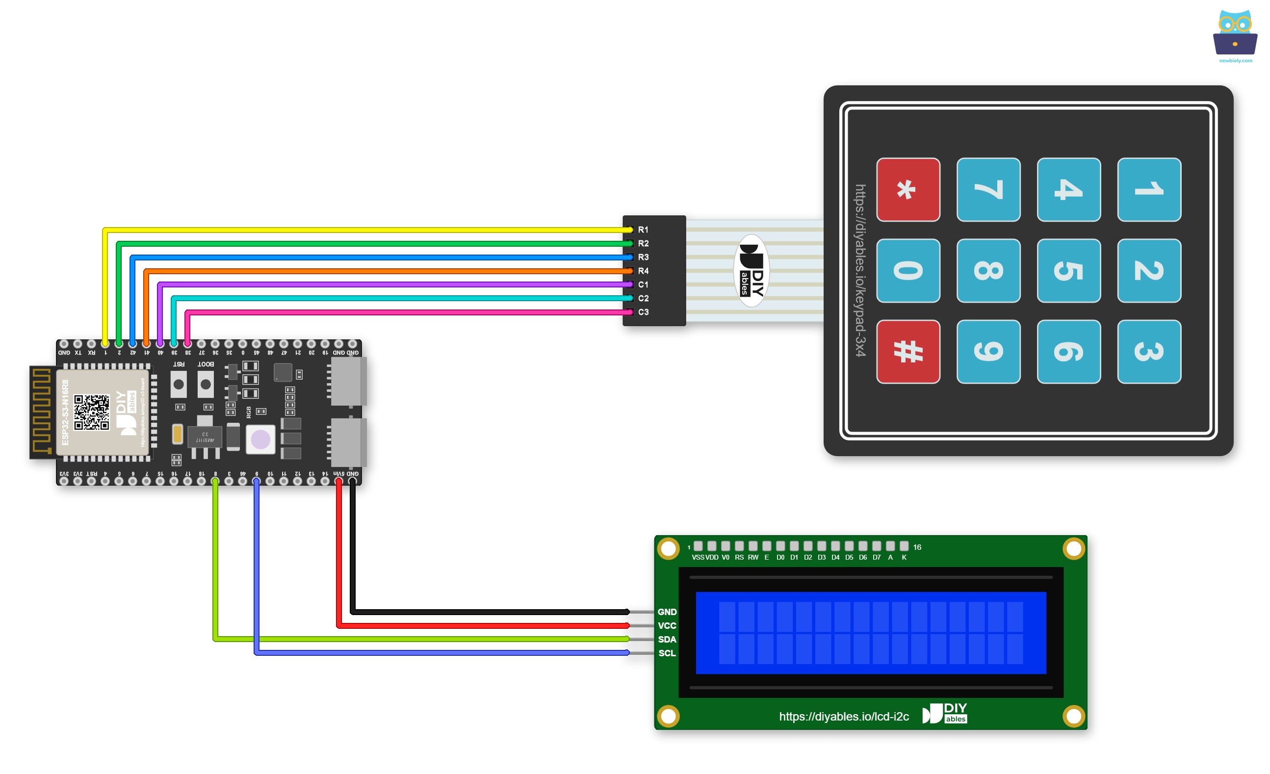
This image is created using Fritzing. Click to enlarge image
If the project will run for a long time, or sit inside a box, it is better to fix the wires with screws. Simply plug the ESP32 S3 into a Screw Terminal Block for ESP32 S3. This is how it looks with the screw terminal board:
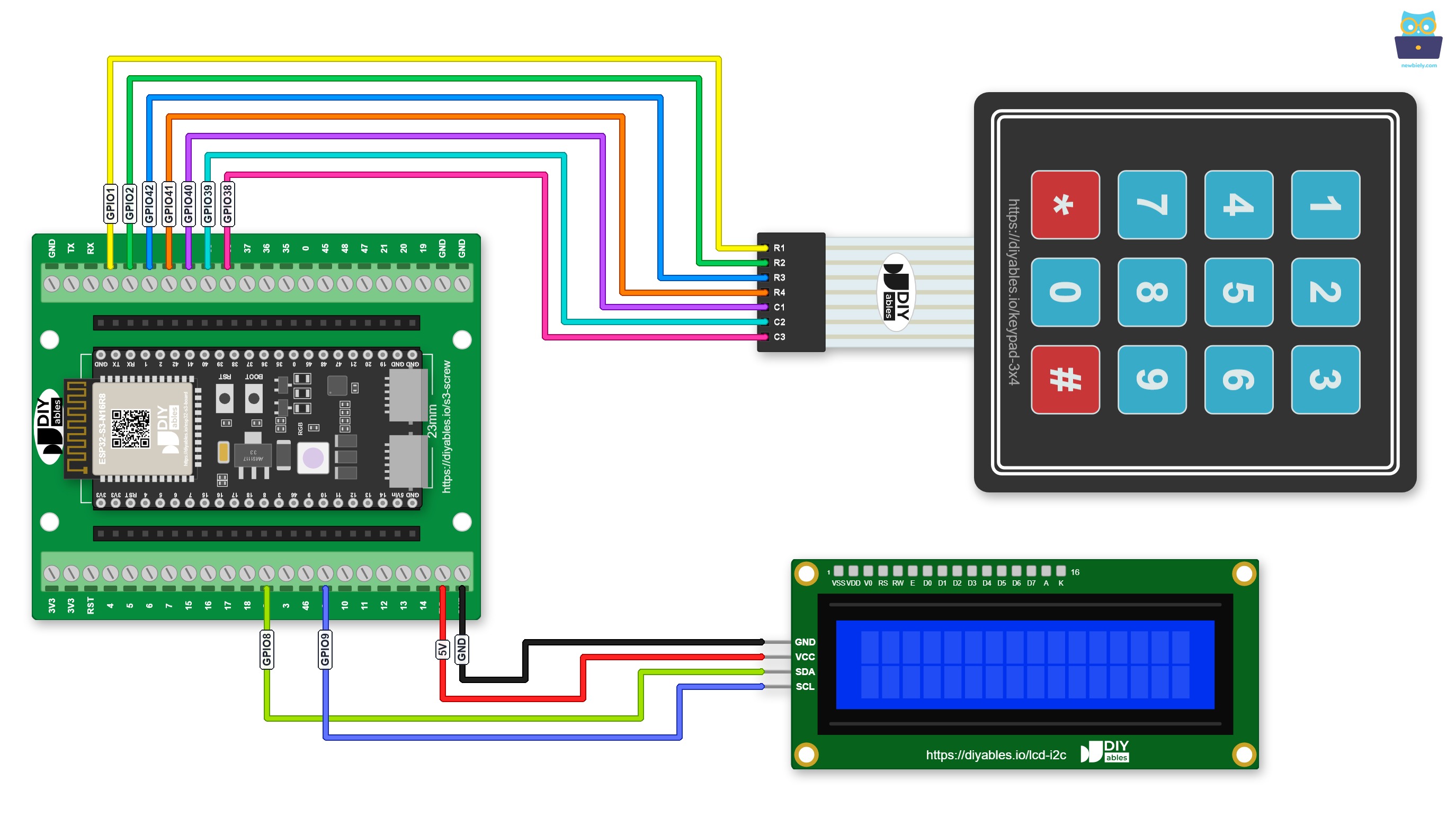
This image is created using Fritzing. Click to enlarge image
Another choice is a GPIO Breakout Board for ESP32 S3. Each GPIO has a signal pin with 3.3V and GND pins next to it, as shown below:
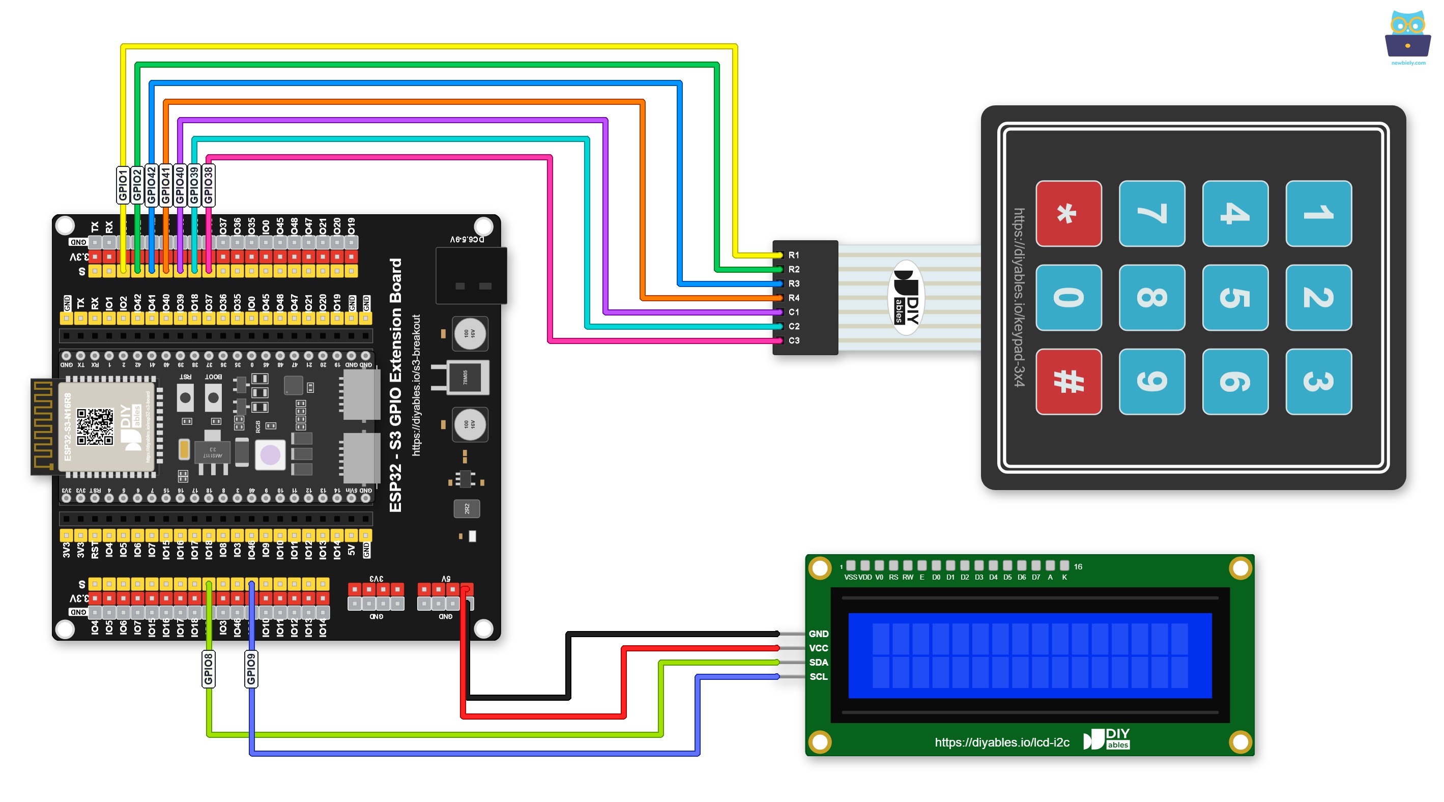
This image is created using Fritzing. Click to enlarge image
- Wiring diagram between ESP32 S3 and Keypad 4x4
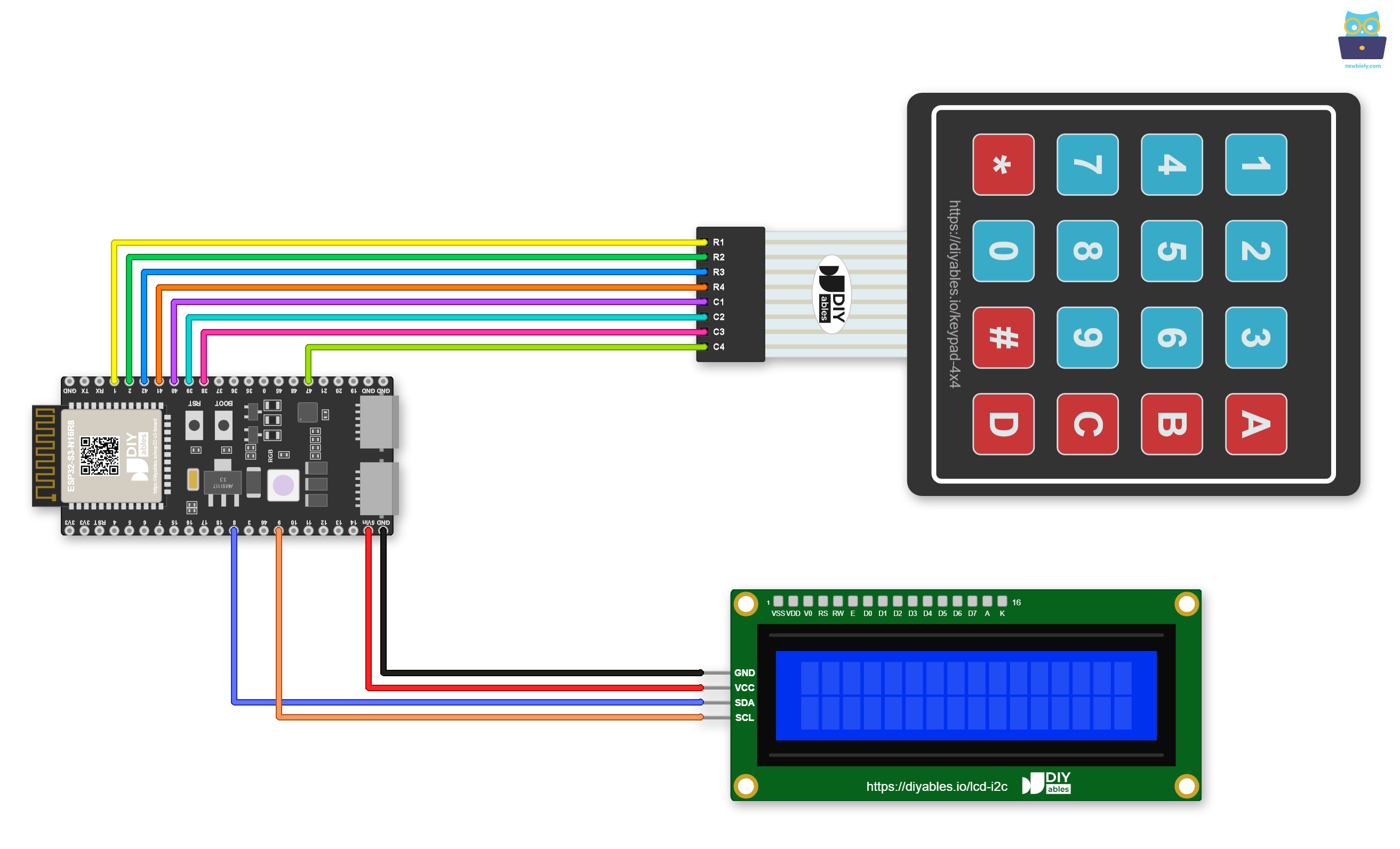
This image is created using Fritzing. Click to enlarge image
Jumper wires are good for a quick test, but not for a final build. A Screw Terminal Block for ESP32 S3 solves this. Plug the ESP32 S3 into it and screw the wires in. The wiring stays the same. Only the wires now go to the screw terminals, as shown below.
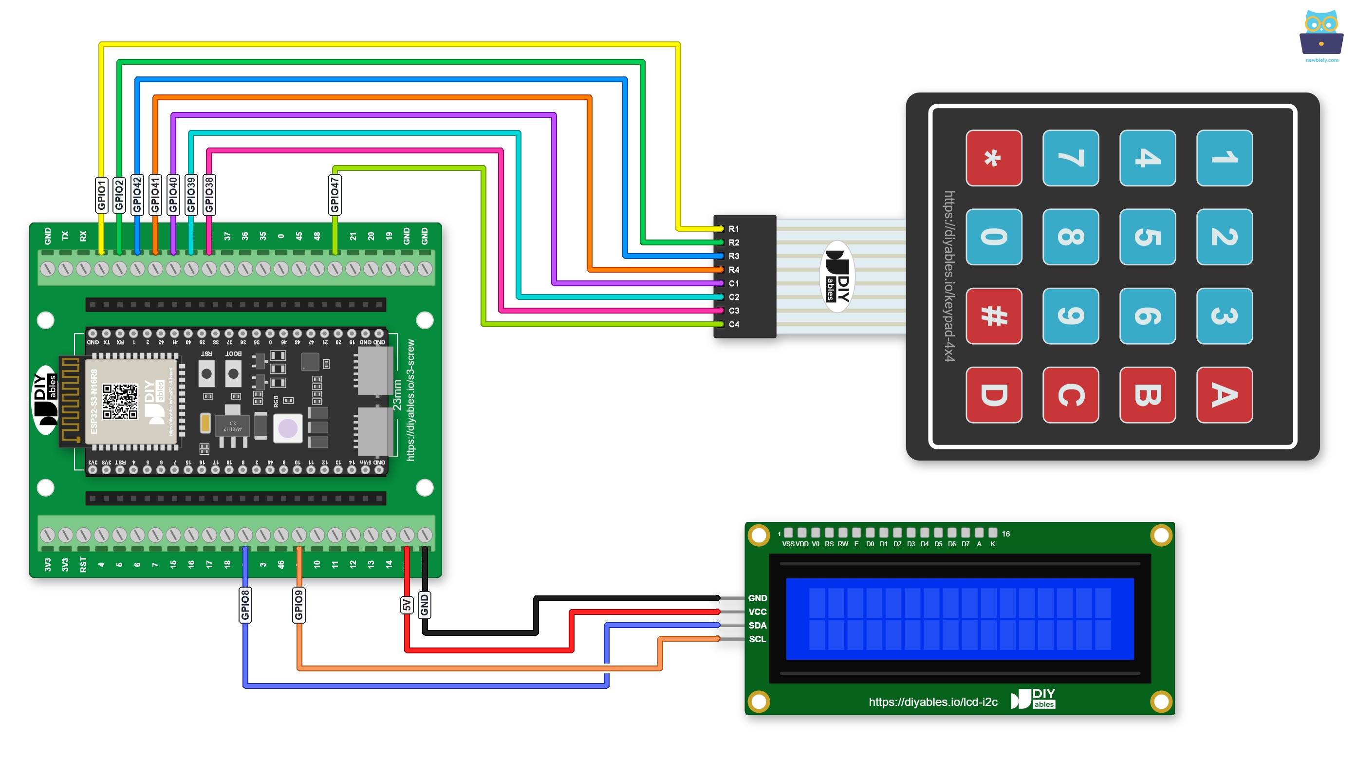
This image is created using Fritzing. Click to enlarge image
You can also use a GPIO Breakout Board for ESP32 S3. It gives each GPIO its own S, 3.3V and GND pins, so module wires plug straight in:
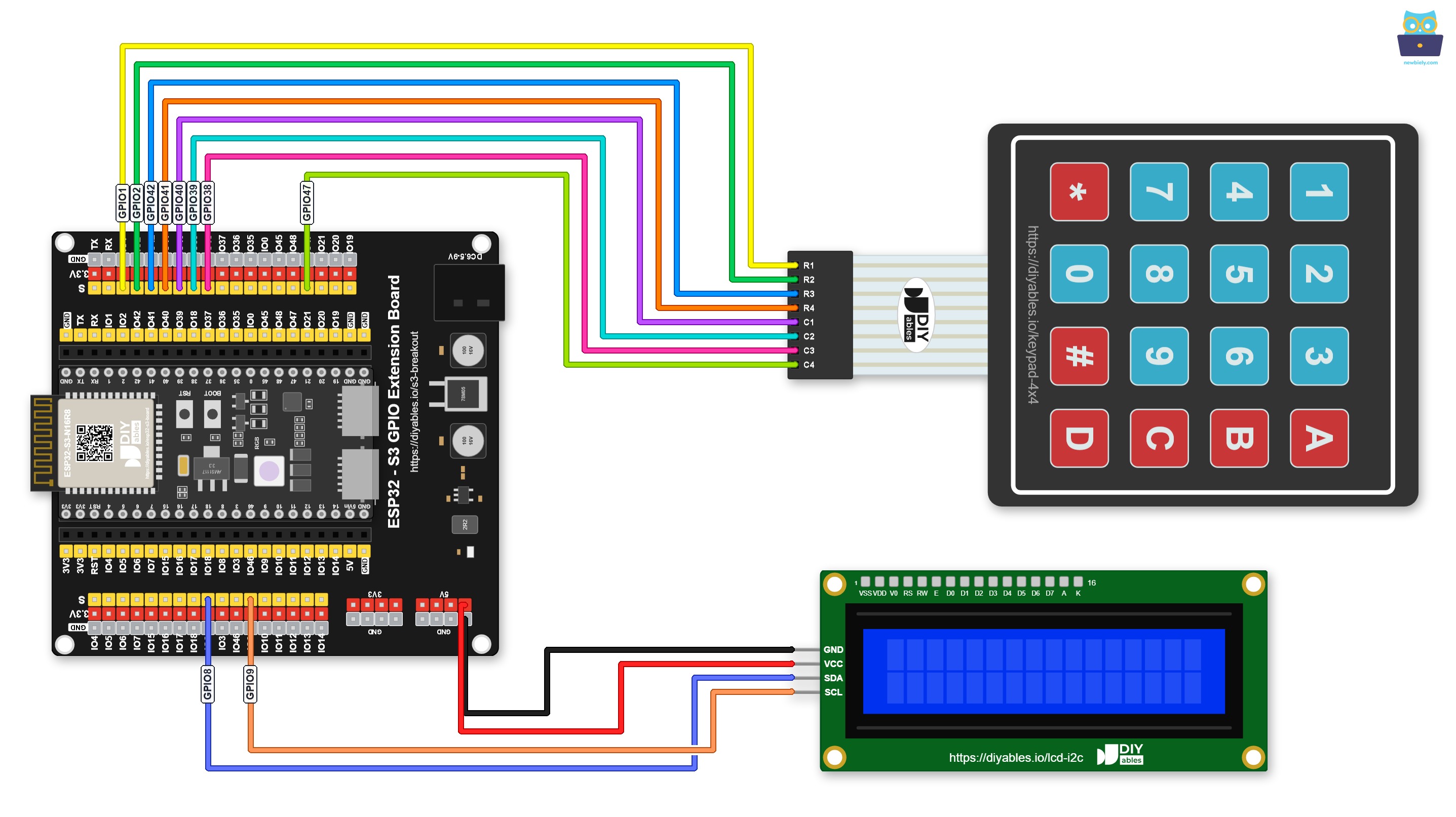
This image is created using Fritzing. Click to enlarge image
Safety Notes
Always connect the LCD I2C VCC pin to the 5V (VBUS) rail rather than the 3.3V rail — the LCD backlight and driver circuit require 5V and will produce dim or no output at lower voltages. The keypad signal lines run at 3.3V logic, which the ESP32 S3 GPIOs handle natively, so no level shifting is needed between the keypad and the board.
| Component | Pin | ESP32 S3 Pin |
|---|---|---|
| Keypad 3x4 | Row 1 | GPIO1 |
| Keypad 3x4 | Row 2 | GPIO2 |
| Keypad 3x4 | Row 3 | GPIO42 |
| Keypad 3x4 | Row 4 | GPIO41 |
| Keypad 3x4 | Col 1 | GPIO40 |
| Keypad 3x4 | Col 2 | GPIO39 |
| Keypad 3x4 | Col 3 | GPIO38 |
| LCD I2C | VCC | 5V |
| LCD I2C | GND | GND |
| LCD I2C | SCL | GPIO9 (I2C Clock) |
| LCD I2C | SDA | GPIO8 (I2C Data) |
ESP32 S3 Code - Keypad 3x4 - LCD I2C
The following code initializes the 3x4 keypad and the LCD I2C display, then enters a loop that polls the keypad for a pressed key and prints it to the LCD in real time. It uses the keypad library by Mark Stanley and Alexander Brevig to handle matrix scanning, and the DIYables LCD I2C library to keep display updates to a single, readable function call.
※ NOTE THAT:
The LCD I2C address can be different from each manufacturer. In the code, we used address of 0x27 that is specified by DIYables manufacturer. If your LCD displays nothing, try address 0x3F instead.
Detailed Instructions
- New to ESP32 S3? Complete our Getting Started with ESP32 S3 guide first.
- Wire the keypad and LCD I2C to the ESP32 S3 following the wiring diagram above.
- Connect the ESP32 S3 board to your PC using a USB Type-C cable.
- Open Arduino IDE on your PC.
- Select the correct ESP32 S3 board and COM port from the Tools menu.
- Click the Libraries icon on the left bar of the Arduino IDE.
- Type "keypad" in the search box, then look for the keypad library by DIYables.
- Click the Install button to install the keypad library.
- Search for DIYables_Keypad created by DIYables.io and click the Install button.
- Type "DIYables LCD I2C" in the search box, then look for the DIYables_LCD_I2C library by DIYables.
- Click the Install button to install the DIYables_LCD_I2C library.
- Search for DIYables LCD I2C created by DIYables.io and click the Install button.
- Copy the above code and paste it into Arduino IDE.
- Click the Upload button to compile and upload the code to your ESP32 S3.
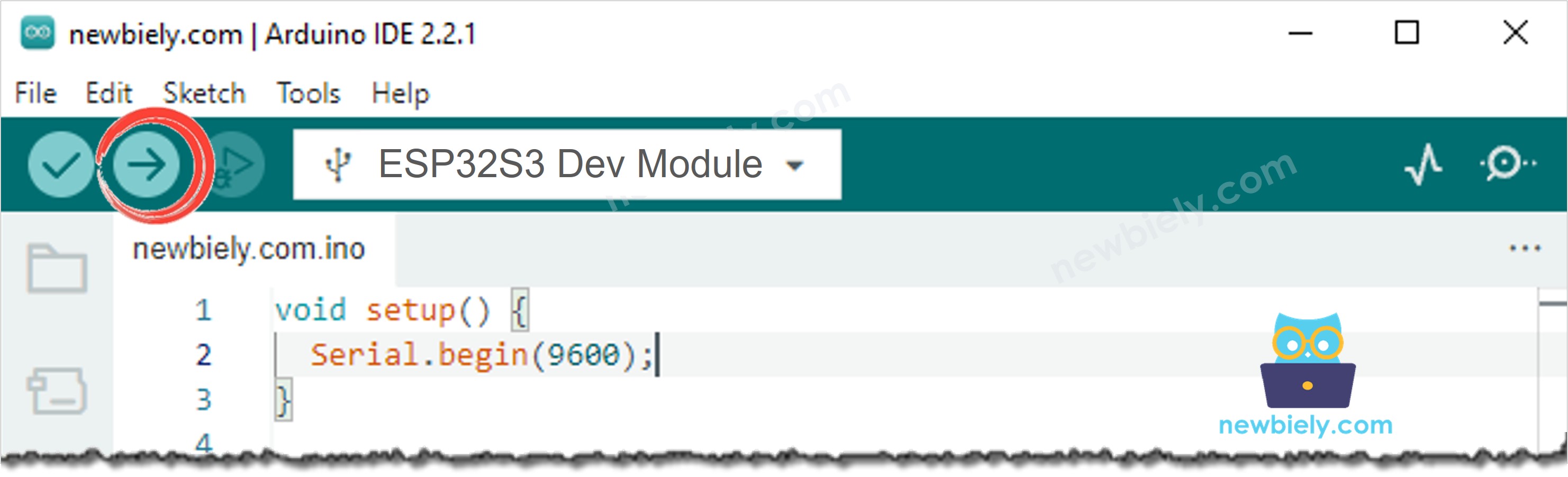
- Press some keys on the keypad.
- Watch the pressed characters appear on the LCD display.
- Pro Tip: If the LCD does not display anything, adjust the contrast potentiometer on the back of the LCD module and verify the I2C address in the code matches your module (try 0x3F if 0x27 does not work). See Troubleshooting on LCD I2C for more help.
Serial Monitor Output
The following Serial Monitor output shows the ESP32 S3 detecting key presses from the 3x4 keypad and printing each pressed character. Each line is timestamped so you can verify that every press is captured immediately and in the correct order.
ESP32 S3 Code - Keypad 4x4 - LCD I2C
The following code adapts the keymap and pin configuration for a 4x4 matrix keypad while keeping the same LCD I2C display logic. Switching from a 3x4 to a 4x4 keypad adds the letters A, B, C, and D, giving you a richer character set for menu systems or access-control interfaces.
Application and Project Ideas
Once you can capture keypad input and display it on the LCD with your ESP32 S3, you can extend this project into a wide range of practical input-driven applications.
- PIN-entry lock: Collect a sequence of key presses, compare it with a stored PIN, and unlock a relay or solenoid when the codes match.
- Calculator: Parse numeric keys and operators typed on the keypad, evaluate the expression, and display the result on the LCD.
- Menu navigation system: Use the keypad to scroll through options on the LCD and select actions such as toggling outputs or adjusting settings.
- Access-control terminal: Log each key press with a timestamp to an SD card and display access-granted or access-denied messages on the LCD.
- Simple alarm panel: Let the user arm or disarm an alarm by entering a code on the keypad, with status messages shown on the LCD.
- Data entry terminal: Use the keypad to enter numeric values for setpoints, thresholds, or configuration parameters that are stored in flash memory.
Video Tutorial
Watch the step-by-step video walkthrough for this ESP32 S3 project below.
Challenge Yourself
Now that key presses are appearing on the LCD with your ESP32 S3, try these progressively harder challenges to deepen your understanding and build more capable input interfaces.
- Beginner: Modify the sketch to clear the LCD after every five key presses so the display always shows only the most recent input.
- Beginner: Add a backspace feature — pressing the star key (*) removes the last character from the LCD display.
- Intermediate: Implement a simple four-digit PIN check: collect four key presses, compare the result to a stored PIN, and display "ACCESS GRANTED" or "ACCESS DENIED" on the LCD.
- Intermediate: Add a timeout so the LCD clears automatically if no key is pressed within ten seconds, helping to protect sensitive input in a shared environment.
- Advanced: Build a numeric calculator that evaluates simple arithmetic expressions entered on the keypad and shows the result on the second row of the LCD.
- Advanced: Store a user-configurable PIN in ESP32 S3 flash memory so it survives power cycles, and add a setup mode that lets the user change the PIN through the keypad itself.