
ESP32 S3 Camera - Smart Video Doorbell with a Button
A shop doorbell with a camera costs a lot of money and needs a paid account. This one costs a few euros and needs nothing but your WiFi.
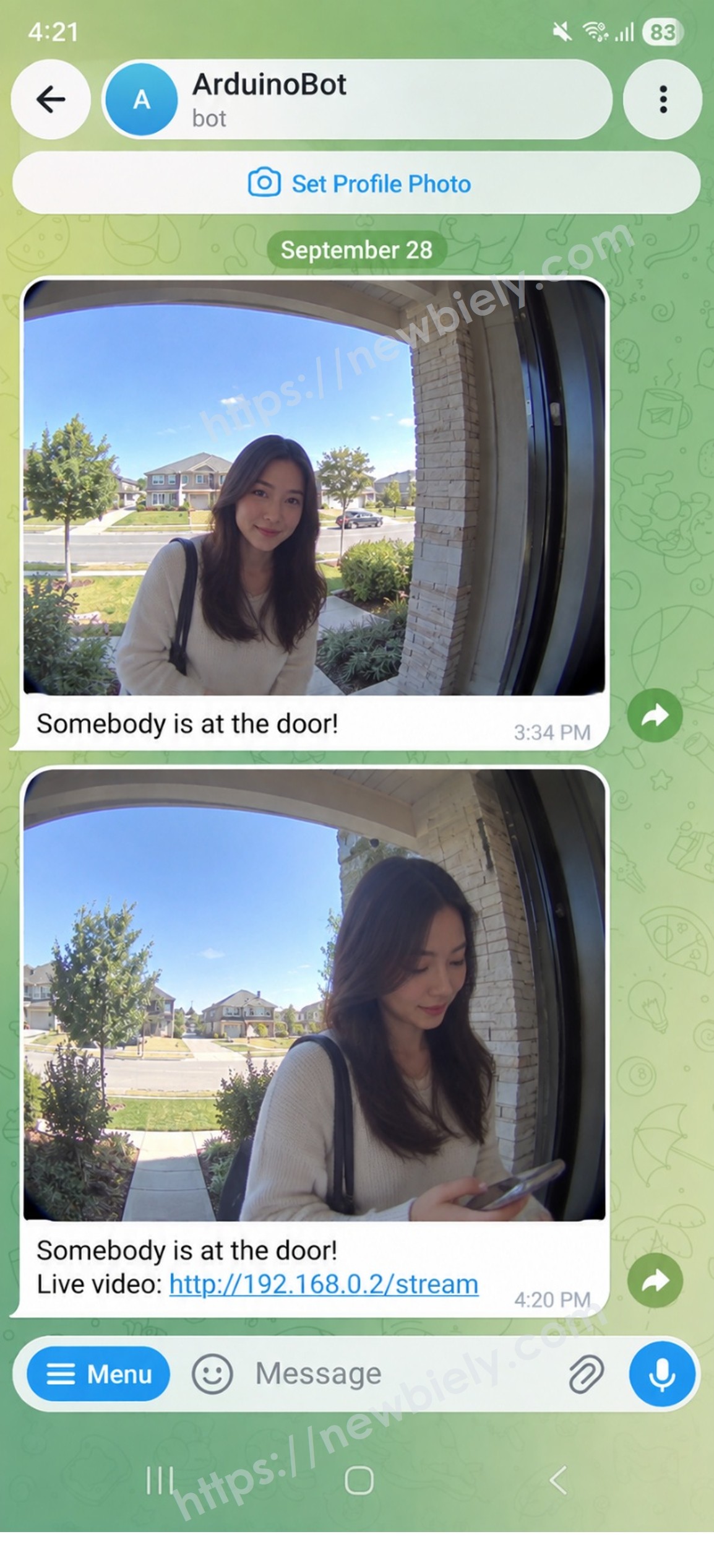
A visitor presses the button. The ESP32 S3 takes a photo and sends it to your phone with Telegram, together with a link to the live video. You look at the photo at once, and you tap the link when you want to see what is happening right now. The small LED on the board answers the visitor, so they know the bell worked.
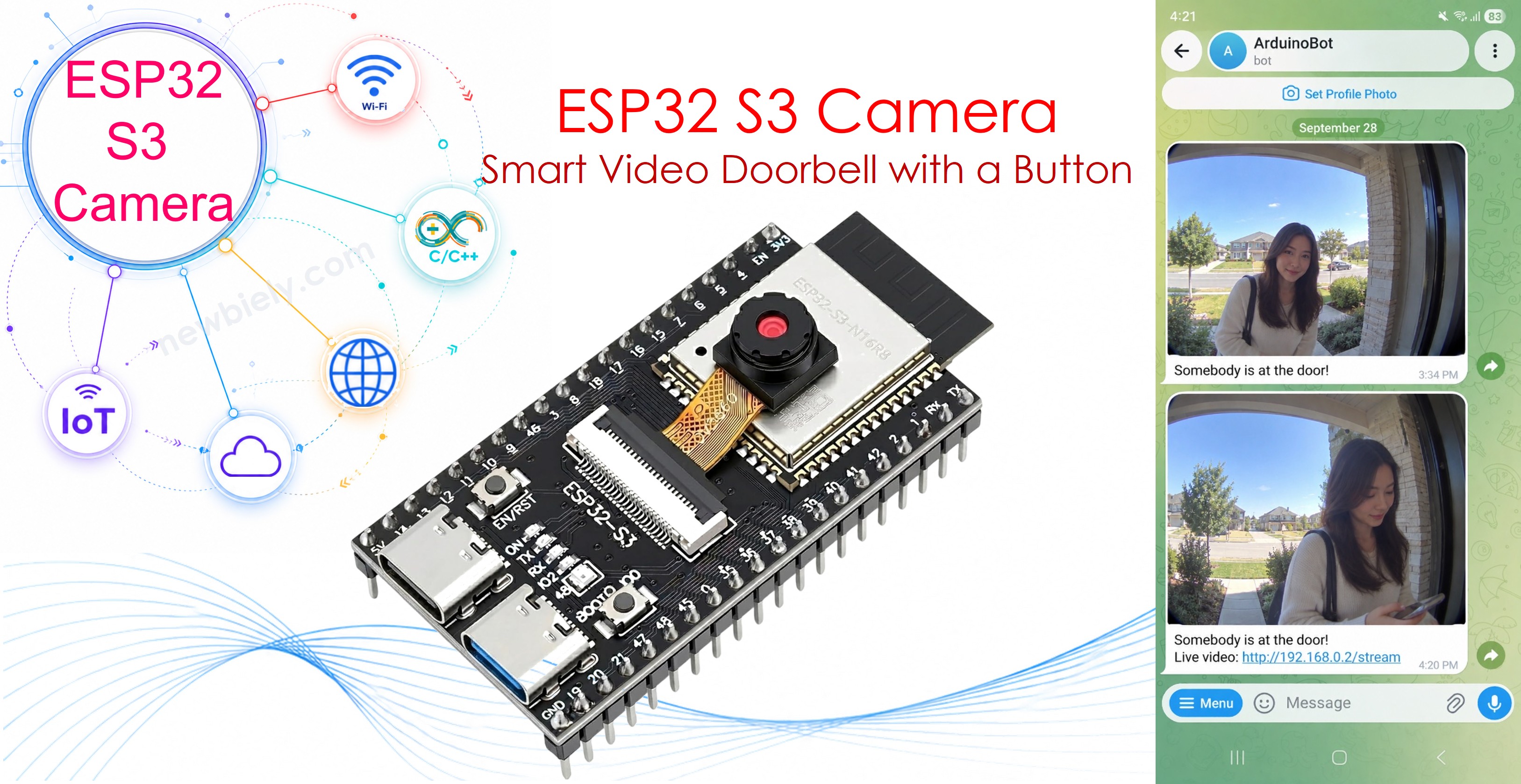
What you'll build:
- A doorbell button that takes a photo of the visitor
- A Telegram message with the photo and a link to the live video
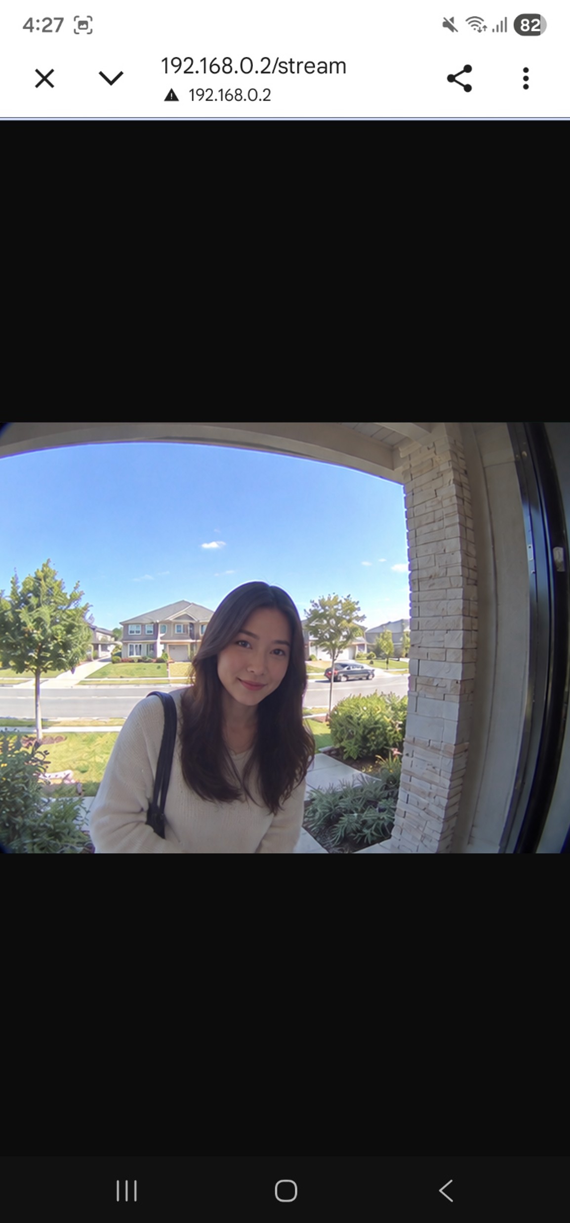
- A live video page that anybody with the link can open on a phone or a computer
- An LED that answers the visitor, so they know the bell worked
- A quiet time, so a child pressing the button ten times does not send ten photos
Hardware Preparation
Or you can buy the following kits:
| 1 | × | DIYables Sensor Kit (18 sensors/displays) |
Additionally, some of these links are for products from our own brand, DIYables .
※ NOTE THAT:
The ESP32 S3 camera board has 40 pins, but the screw terminal block and the breakout board have 44 pins. They still work together. Put the camera board in the center of the 44-pin board, so 2 pins stay free on the left side and 2 pins stay free on the right side.
The screw terminal block lets you connect wires with a screwdriver, with no soldering. The breakout board gives you easy pin headers for a breadboard.
How It Works
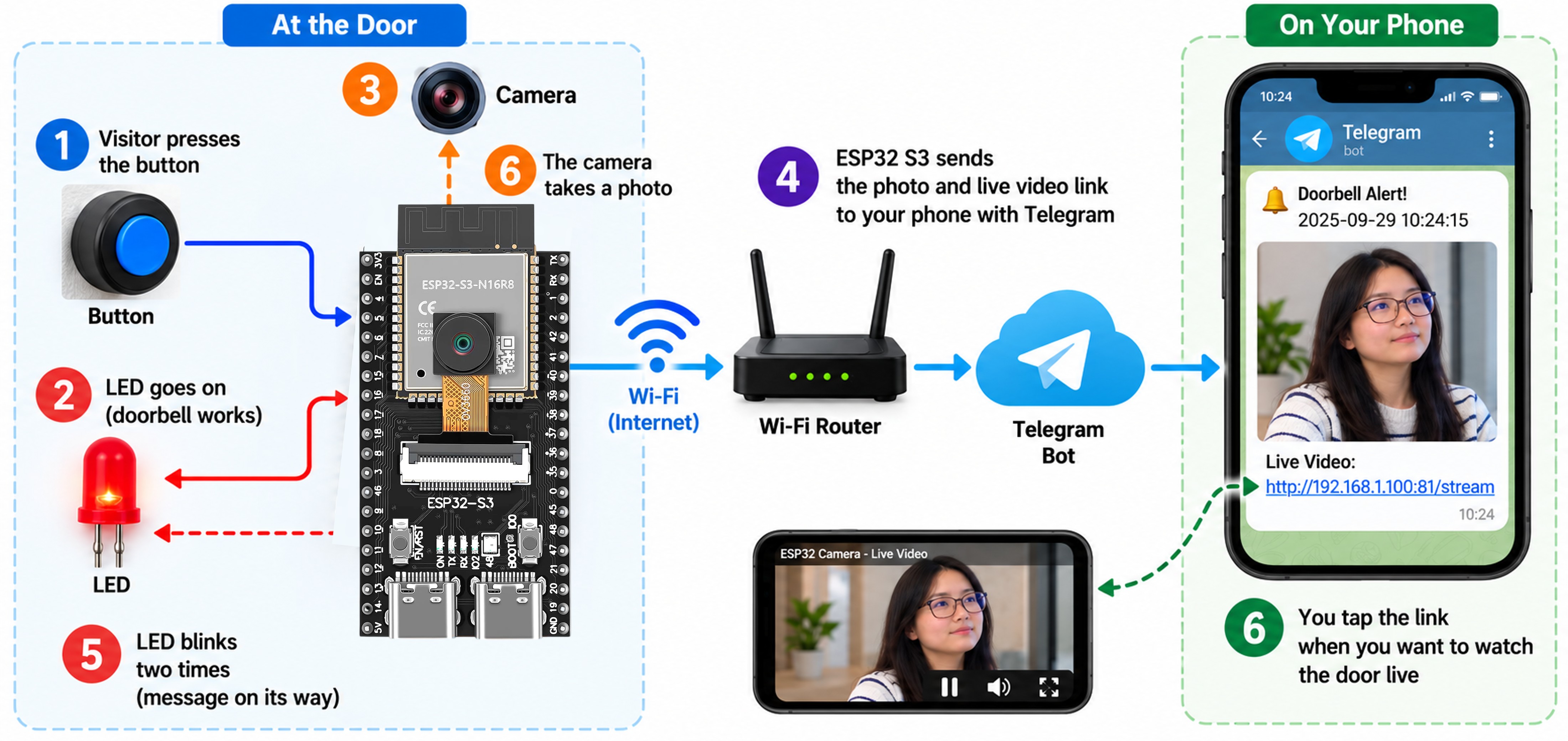
The whole project is six steps:
| Step | What happens |
|---|---|
| 1 | A visitor presses the button |
| 2 | The LED goes on, so the visitor sees that the bell works |
| 3 | The camera takes a photo |
| 4 | The ESP32 S3 sends the photo AND the live video link to your phone with Telegram |
| 5 | The LED blinks two times. The visitor knows the message is on its way. |
| 6 | You tap the link when you want to watch the door live |
The message on your phone looks like this:


ArduinoBot
Why a Photo AND a Link?
A photo and a live video are good at different things:
| Photo in the message | Live video link | |
|---|---|---|
| Arrives by itself | Yes | No, you must tap it |
| Works from anywhere | Yes, always | Only at home, unless you do port forwarding |
| Shows one moment | Yes | No, it shows now |
| Shows what the visitor does next | No | Yes |
| Costs battery and WiFi | A few seconds | While you watch |
So the photo tells you that somebody is there, and the link lets you see what they are doing now. That is how a real video doorbell works.
※ NOTE THAT:
The live video stops by itself after 60 seconds. This is on purpose. While somebody watches the video, the board is busy and cannot see the button. The time limit makes sure the doorbell always comes back to life. To change it, change the line #define STREAM_SECONDS 60.
The LED Talks to the Visitor
A doorbell with no answer is a bad doorbell. Nobody knows whether it worked, so people press it again and again. The small colour LED that is already on the board gives an answer for every situation:
| What the LED does | What it means |
|---|---|
| 3 blinks when you switch the board on | The doorbell is ready |
| Stays on | The photo is being taken and sent. Please wait. |
| 2 slow blinks | The photo was sent. Somebody will come. |
| 5 fast blinks | Something went wrong. No WiFi, or Telegram refused. |
| 1 long blink | You pressed too soon after the last ring. |
※ NOTE THAT:
This is the part that makes the project feel finished. The code is only a few lines, but a visitor who gets an answer will not press the button twenty times.
Why a Button Needs Help
A push button is two pieces of metal. When they touch, they bounce against each other many times in the first milliseconds. Without protection, one press looks like five presses, and your phone gets five photos.
You could write the waiting code yourself, but the ezButton library already does it. Three lines are the whole job:
Then you simply ask whether somebody pressed it:
※ NOTE THAT:
isPressed() is true only in the moment the button goes down, not while it is held. So one press does the work one time, even when a visitor keeps the button down for three seconds.
※ NOTE THAT:
button.loop() must be the first line inside your own loop(). It is the line that reads the pin and does the waiting. Forget it, and the button never works.
Overview of the Button Module
We use a button module, not a bare push button. A module is the same button, but it sits on a small board that already has the resistor on it, and it has three clean pins. You only push three wires on, and nothing can be wrong way round.

The resistor on the module is a pull-down resistor. It holds the pin at GND while nobody touches the button:
| Button | Pin reads |
|---|---|
| Nobody touches it | LOW, the resistor holds it down |
| Somebody presses it | HIGH, the button joins the pin to 3.3V |
We tell the library about it with one word:
※ NOTE THAT:
EXTERNAL_PULLDOWN means "the resistor is outside the chip, on the module, and it pulls the pin down". The library then knows that HIGH means pressed.
Do you have a bare push button instead of a module? Then the board must make the resistor itself. The code has both lines. Swap the // marks:
| What you have | Line to use | Wiring |
|---|---|---|
| Button module | ezButton button(BUTTON_PIN, EXTERNAL_PULLDOWN); | VCC, GND and OUT |
| Bare push button | ezButton button(BUTTON_PIN); | One leg to the pin, one leg to GND |
※ NOTE THAT:
Never use both. With a bare button you need the resistor inside the board, and with a module you must not use it, because the module already has one.
Make Your Telegram Bot
You need a bot token and a chat ID. This takes three minutes.
Step 1: Make Your Bot
- Install Telegram on your phone, and make an account.
- In Telegram, search for @BotFather. It has a blue tick.
- Open the chat with BotFather and talk to it like this:
BotFather
- Copy the bot token from the last message and keep it safe.
Step 2: Find Your Chat ID
- In Telegram, search for the name of your new bot and open the chat.
- Send any message to your bot, for example hello. This step is necessary. Telegram does not let a bot write to you before you have written to it.
ArduinoBot
- Open this address in your web browser. Put your own bot token in the place of <YOUR_BOT_TOKEN>:
- The browser shows a long text. Look for "chat":{"id":. The number after it is your chat ID.
※ NOTE THAT:
Does the browser show {"ok":true,"result":[]} with nothing inside? Then you did not send a message to your bot yet. Go back to step 2, send hello to your bot, then load the address again.
※ NOTE THAT:
Never show your bot token to anybody, and never put it on a website or on GitHub. If it leaks, send /revoke to BotFather and you get a new one.
The Live Video Link
The link inside the Telegram message comes from one line at the top of the code:
| What you write there | What the link becomes | Where it works |
|---|---|---|
| Nothing (empty) | http://192.168.0.2/stream, the address of the board | Only at home, on the same WiFi |
| Your own address | http://my-house.duckdns.org:8080/stream | From anywhere in the world |
The code chooses by itself:
※ NOTE THAT:
Start with the empty setting. Test everything at home first. Only when the doorbell works well, think about opening it to the internet.
Why the Link May Not Work Outside Your Home
The address of the board, for example 192.168.0.2, is a private address. It lives only inside your house. Your phone finds it when it is on your own WiFi, but the internet cannot see it at all. So the link works at home, and does nothing when you are away.
To open the link from outside, you need a public address: the address of your router, together with port forwarding, so that the router passes the visitor on to the board. Every router does this a little differently, so look in the manual of your own router, or ask your internet company.
When you have it, write that address into the code:
※ NOTE THAT:
Most routers get a new public address from time to time, and your link then stops working. A free DDNS name, for example from DuckDNS or No-IP, always points at your house, so you can write http://my-house.duckdns.org:8080 and forget about it.
Put a Password on It
When you open your camera to the internet, anybody who finds the address can watch your door. Programs scan the whole internet all day looking for open cameras.
So whenever you use PUBLIC_ADDRESS, switch the password on:
The web browser asks for them the first time, and remembers them after that.
※ NOTE THAT:
This is a simple password, sent over http and not https. It stops a stranger who finds your address, but it is not strong enough for a bank. For a front door it is a fair balance. Do you want more safety? Then do not open the camera to the internet at all, and watch the live video only when you are at home.
Wiring Diagram between Button and ESP32 S3
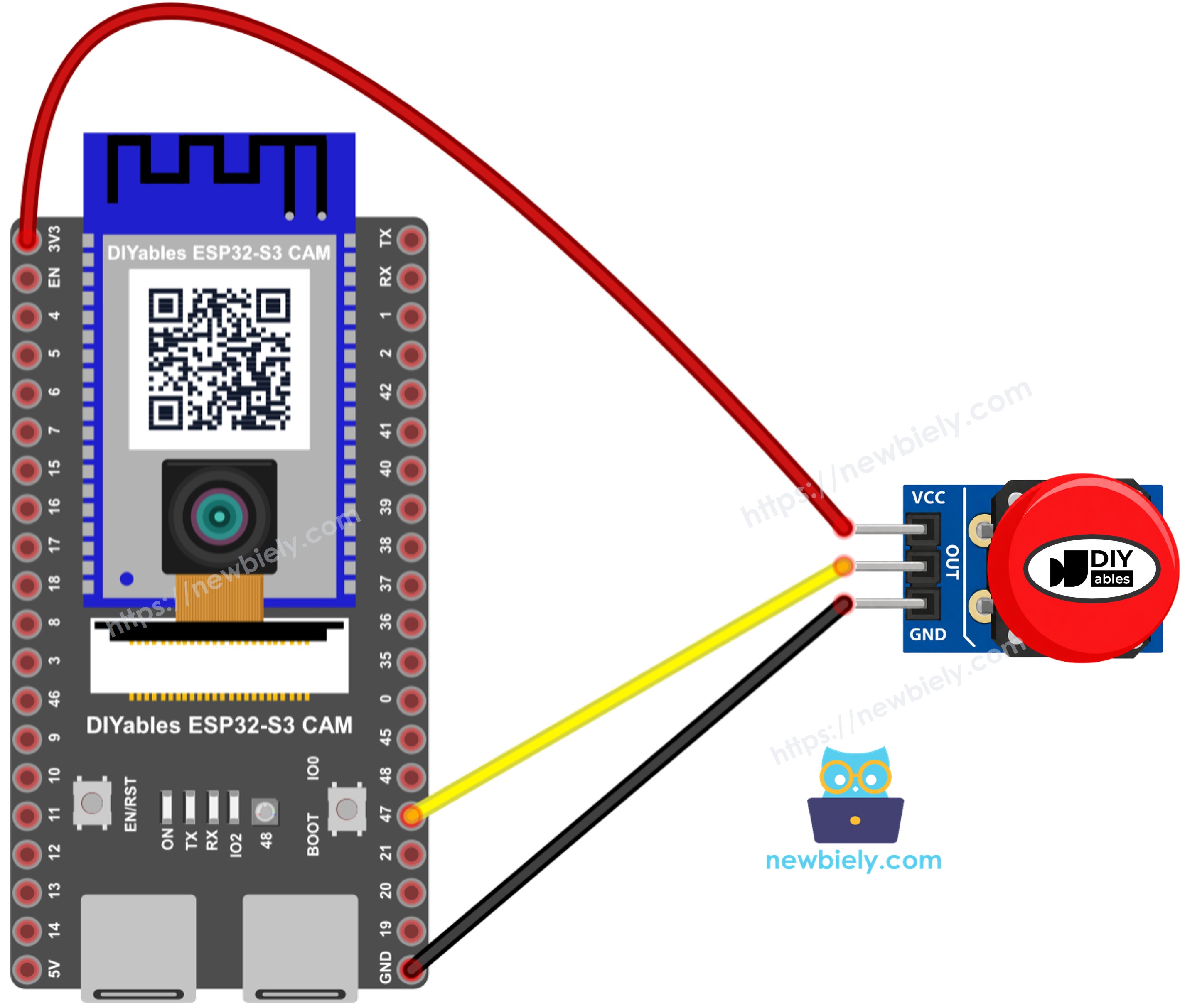
This image is created using Fritzing. Click to enlarge image
| Button Module Pin | ESP32 S3 Pin |
|---|---|
| VCC (or +) | 3.3V |
| GND (or -) | GND |
| OUT (or S, or SIG) | GPIO47 |
That is the whole wiring. Three wires, and no resistor.
※ NOTE THAT:
You do not need an LED. The board already has a small colour LED on it, and the code uses that one:
※ NOTE THAT:
Has your board no LED on it? Then connect your own LED with a 220 ohm resistor to a free pin, for example GPIO21, and change the line to #define LED_PIN 21.
Safety Notes
Use 3.3V for the button module, not 5V. The ESP32 S3 pins are made for 3.3V, and 5V can damage them.
The button module needs no extra resistor, because the resistor is already on the module.
The camera uses GPIO4, 5, 6, 7, 8, 9, 10, 11, 12, 13, 15, 16, 17 and 18. Do not use these pins. GPIO47 is free, so we use it for the button.
※ NOTE THAT:
A real doorbell button has four legs, but only two of them are needed. If your button does nothing, turn it a quarter round on the breadboard and try again. Two legs that are already joined inside will never work.
Install the Libraries
This project needs two libraries.
DIYables ESP32 WebServer makes the live video page:
- Open the Arduino IDE.
- Click the Libraries icon on the left bar.
- Type DIYables ESP32 WebServer into the search box.
- Find the library by DIYables.io and click INSTALL.
- Search for DIYables ESP32 WebServer created by DIYables.io and click the Install button.
ezButton reads the button and takes care of the bouncing:
- Type ezButton into the same search box.
- Find the library by ArduinoGetStarted.com and click INSTALL.
- Search for ezButton created by ArduinoGetStarted.com and click the Install button.
Arduino IDE Settings for ESP32 S3 Camera
The camera does not work with the default settings of the Arduino IDE. You must change some items in the Tools menu before you upload the code.
| Tools Menu Item | Select This |
|---|---|
| Board | ESP32S3 Dev Module |
| Flash Size | 16MB (128Mb) |
| PSRAM | OPI PSRAM |
| Partition Scheme | Huge APP (3MB No OTA/1MB SPIFFS) |
| CPU Frequency | 240MHz (WiFi) |
| USB Mode | Hardware CDC and JTAG |
| Upload Mode | UART0 / Hardware CDC |
| Upload Speed | 921600 |
| USB CDC On Boot | Enabled |
ESP32 S3 Code
Change your WiFi, your bot token and your chat ID at the top of the code.
The settings you can change:
| Name | Start with | What it does |
|---|---|---|
| PUBLIC_ADDRESS | empty | The link in the message. Empty means the address of the board. |
| USE_PASSWORD | false | Set it to true when you open the camera to the internet |
| QUIET_TIME | 10000 | Milliseconds to wait before the next ring |
| STREAM_SECONDS | 60 | The live video stops by itself after this many seconds |
| DEBOUNCE_TIME | 50 | Milliseconds to wait, because the button bounces |
Detailed Instructions
- New to ESP32 S3? Complete our Getting Started with ESP32 S3 guide first.
- Make your Telegram bot and find your chat ID. See the steps above.
- Install the DIYables ESP32 WebServer and ezButton libraries.
- Unplug the USB cable, then wire the button module as in the table above.
- Copy the above code and paste it into the Arduino IDE.
- Change WIFI_SSID, WIFI_PASSWORD, BOT_TOKEN and CHAT_ID. Leave PUBLIC_ADDRESS empty for now.
- Change the settings in the Tools menu. See the table above.
- Compile and upload the code to the ESP32 S3 board by clicking the Upload button in Arduino IDE.
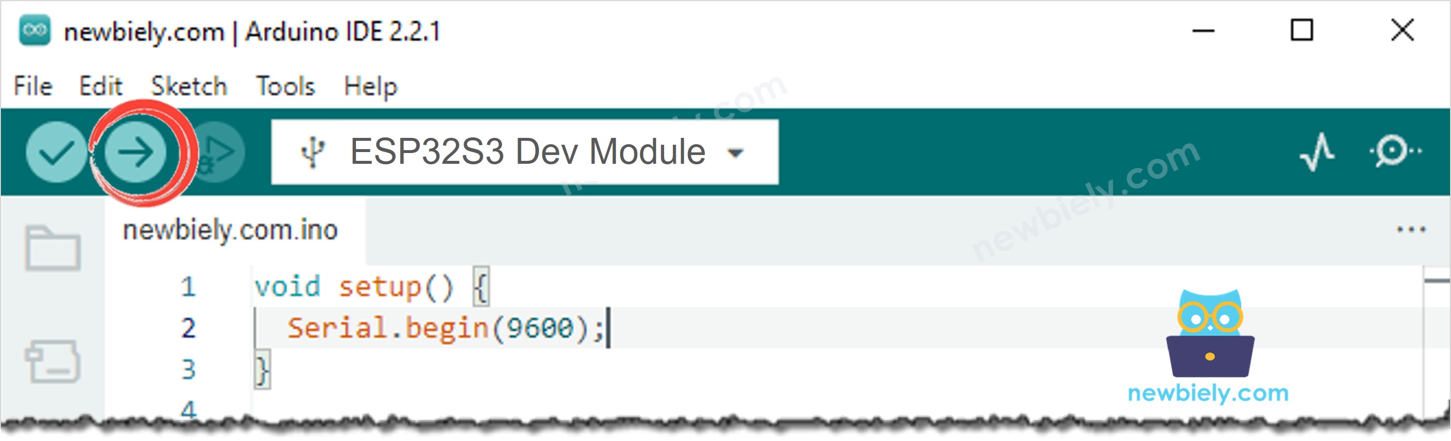
- Open the Serial Monitor in Arduino IDE.
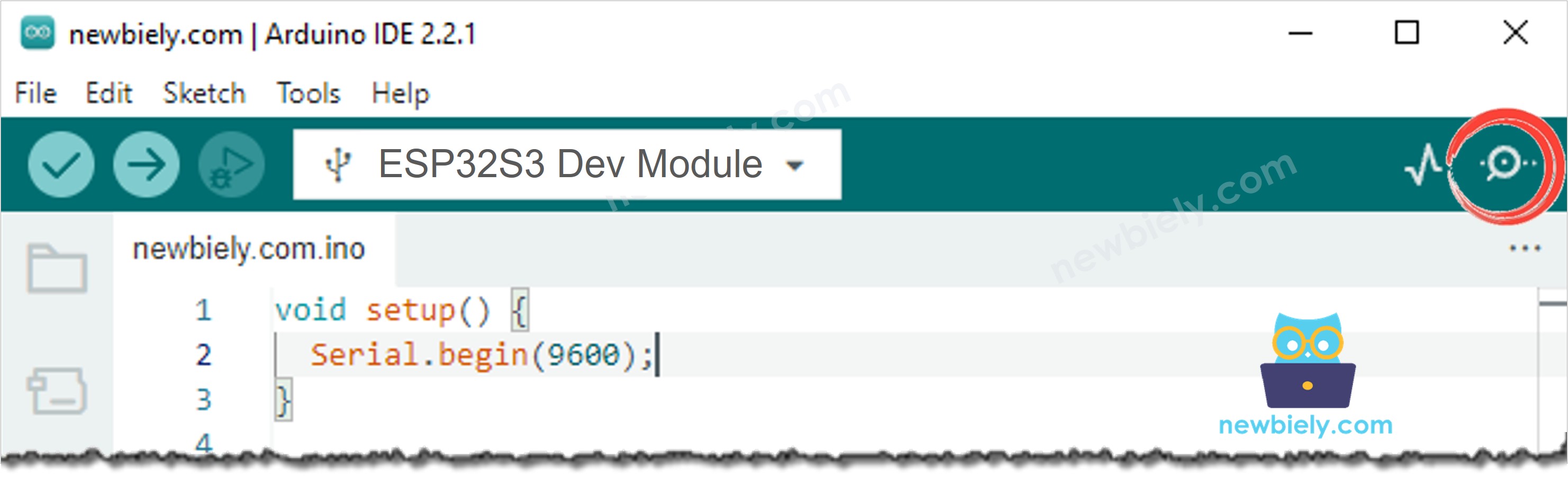
- Press the RESET button one time. The LED blinks three times, so you know the doorbell is ready.
- Point the camera at your face and press the doorbell button.
- The LED stays on for a moment, then blinks two times.
- Look at your phone. The photo is in your Telegram chat, with the link under it.
ArduinoBot
- Tap the link. Your phone opens the live video of your door.
- Watch for a moment, then close the page. The doorbell is ready again.
- Pro Tip: Do you want the link to work when you are not at home? Read The Live Video Link above, and do the port forwarding.
Serial Monitor
The following readings were captured in 2026:
※ NOTE THAT:
Too soon after the last ring is the quiet time doing its job. Somebody pressed the button again after 4 seconds, and the code did not send a second photo.
※ NOTE THAT:
Somebody is watching the live video appears when you tap the link. If you never see this line, the link did not reach the board. Read the troubleshooting below.
The two lines at the start tell you what went into the message. When you set PUBLIC_ADDRESS, the second line becomes your own address:
Troubleshooting
Nothing happens when I press the button.
- Check the three wires. VCC to 3.3V, GND to GND, OUT to GPIO47.
- Is button.loop() the first line inside loop()? Without it the library never reads the pin.
- Does your module have a pull-up resistor instead of a pull-down? Then change the code to ezButton button(BUTTON_PIN, EXTERNAL_PULLUP);
- Watch the Serial Monitor while you press. No line there means the wiring, not the code.
The doorbell rings by itself, with nobody there.
The OUT wire is loose, so the pin picks up noise. Push the wire in properly. A module with its own resistor should never do this when it is wired correctly.
One press sends two or three photos.
Increase DEBOUNCE_TIME from 50 to 150.
The LED blinks five times after every press.
Five fast blinks mean the photo could not be sent. Read the Serial Monitor:
- Telegram did not answer at all means the photo went out but nothing came back. Check your internet, and try a phone hotspot, because some networks block Telegram.
- Sending stopped after ... bytes means the WiFi broke in the middle. Move the board closer to the router.
- Cannot connect to Telegram means no internet at all.
- Unauthorized means your bot token is wrong.
- chat not found means your chat ID is wrong.
The Serial Monitor shows Forbidden: bot can't initiate conversation with a user.
You never wrote to your bot. Open Telegram, find your bot, and send it any message. Then press RESET on the board.
The LED never lights up.
The code uses the LED that is on the board. Not every board has one. If yours has none, connect your own LED with a 220 ohm resistor to GPIO21, and change the line to #define LED_PIN 21.
The link in the message does not open anything.
- Leave PUBLIC_ADDRESS empty and try again at home, on the same WiFi as the board. This must work first.
- Your phone must be on the WiFi, not on mobile data. A private address like 192.168.0.2 does not exist outside your house.
- Type http://, not https://. The board does not use https.
The link works at home but not outside.
This is normal with an empty PUBLIC_ADDRESS. To make it work from anywhere, you need port forwarding and a DDNS name. Read The Live Video Link above.
I did the port forwarding, and it still does not work.
- Give the board a fixed address in your router, or the forwarding points at the wrong device after a power cut.
- Some internet companies give you an address that is shared with other houses (CGNAT). Then port forwarding cannot work at all. Ask your company for a real public address.
- Test from mobile data, not from your home WiFi. Many routers cannot open their own public address from inside.
The live video stops after one minute.
That is on purpose. While somebody watches, the board cannot see the button. Reload the page to watch again, or change #define STREAM_SECONDS 60.
The doorbell button does nothing while somebody watches the video.
The board can do one thing at a time. Close the video page, and the button works again. This is also why the video stops by itself after a minute.
The photo shows the visitor from below, or their head is cut off.
Move the camera. A doorbell camera should sit about 150 cm above the ground, so it looks at a face and not at a chest.
The photo is dark in the evening.
The camera cannot see in the dark. See the ESP32 S3 Camera - Add a Flash LED for Night Photos tutorial. A light at a door is also friendly for the visitor.
The photo takes a long time.
Use a smaller image size. FRAMESIZE_VGA (640 × 480) is about half of SVGA.
The Serial Monitor shows nothing after the boot messages.
If your USB cable is in the port named UART, set USB CDC On Boot to Disabled. If it is in the port named USB, set it to Enabled.
Applications
A button, a camera and a message. That small idea fits in many places. Here are practical projects you can build with this code:
- Video doorbell for your house: See the visitor on your phone, from anywhere.
- Doorbell for a deaf person: The photo and the phone alert replace the sound.
- Office reception bell: A visitor rings, and the right person sees who it is.
- Tutorial or garage bell: Know that somebody is at the back door while a machine is loud.
- Help button for an older person: One press sends a photo of the room to a family member.
- Hotel or guest room bell: The owner sees the guest without walking to the door.
- Warehouse delivery bell: The driver rings, and the office sees the lorry.
- Shop service button: A customer asks for help, and a photo shows where they stand.
- School or club entrance: Keep a photo record of every person who rang.
- Photo booth button: Press to take your own picture and get it on your phone.
Video Tutorial
Watch the step-by-step video walkthrough for this ESP32 S3 project below.
Challenges
- Beginner: Change the text Somebody is at the door! to your own message, for example the name of your house.
- Intermediate: Add a buzzer that makes a sound inside the house when the button is pressed, so you hear the bell as well as see it.
- Advanced: Also save every photo to the microSD card, so you keep a record of all your visitors even when the internet is down. See the ESP32 S3 Camera - Save Photo to SD Card When Door Opens tutorial.