
ESP32 S3 - Light Sensor Triggers LED
This tutorial shows you how to use the ESP32 S3 together with a light sensor (LDR) to automatically control an LED based on the ambient light level in the surrounding environment. By reading the analog voltage produced by a light-dependent resistor and comparing it against a defined threshold, you will see a practical example of how analog sensor data can drive digital GPIO outputs on the ESP32 S3.
What you'll build:
- A circuit connecting an LDR light sensor and an LED to the ESP32 S3
- A sketch that continuously reads the analog value from the light sensor via the ESP32 S3 ADC
- A system that automatically turns the LED on when the measured light level drops below a threshold (i.e., it is dark)
- A foundation for building automatic night lights, daylight-controlled relays, and ambient-light monitoring projects
Hardware Preparation
Or you can buy the following kits:
| 1 | × | DIYables ESP32 S3 Starter Kit (ESP32 S3 included) | |
| 1 | × | DIYables Sensor Kit (18 sensors/displays) |
Additionally, some of these links are for products from our own brand, DIYables .
Buy Note: Use the LED Module for easier wiring. It includes an integrated resistor.
The LDR light sensor is very affordable, but it requires a resistor for wiring, which can make the setup more complex. To simplify the wiring, you can use an LDR light sensor module as an alternative.
Overview of LED and Light Sensor
The LDR light sensor and LED make an intuitive pairing for building ambient-light-controlled projects on the ESP32 S3. As light intensity decreases, the LDR resistance rises, which changes the voltage at the analog input pin; the ESP32 S3 reads this voltage via its ADC and compares it against a threshold to decide whether to switch the LED on or off through a GPIO output.
Key Specifications
We have dedicated tutorials covering each component in depth. Each tutorial contains detailed information and step-by-step instructions about hardware pinout, working principle, wiring connection to the ESP32 S3, and Arduino code. Learn more about them at the following links:
Wiring Diagram
Connect the light sensor and LED to your ESP32 S3 by following the diagram below. Double-check all connections before applying power, paying particular attention to the LED polarity, the 220 ohm current-limiting resistor, and the 10 kΩ pull-down resistor used to form a voltage divider with the LDR.
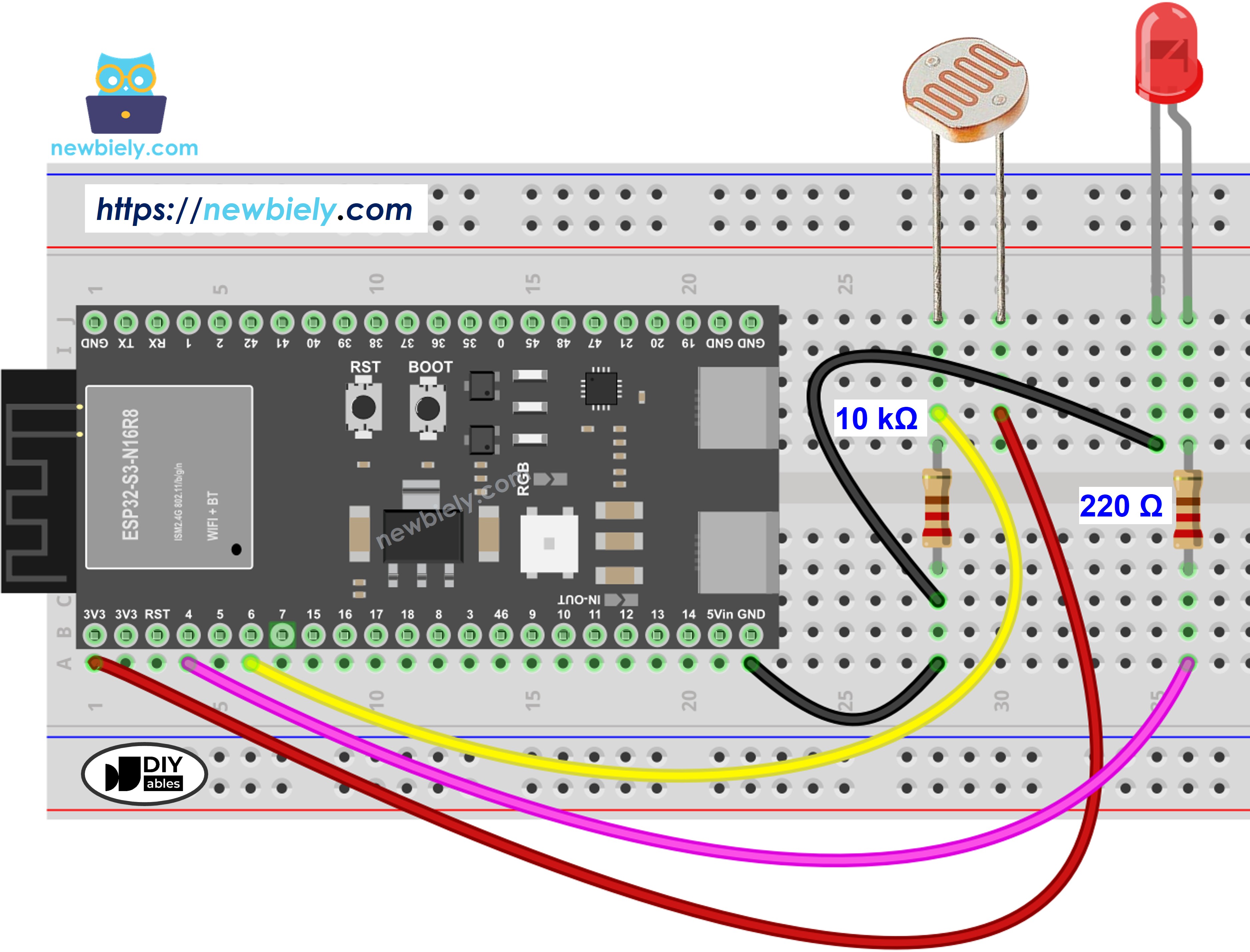
This image is created using Fritzing. Click to enlarge image
Safety Notes
Always include the 220 ohm current-limiting resistor in series with the LED to prevent drawing excessive current through the ESP32 S3 GPIO pin, which can permanently damage the microcontroller. The LDR and 10 kΩ resistor form a voltage divider that keeps the analog signal within the safe 0–3.3V input range that the ESP32 S3 ADC expects — never connect the LDR output directly to a 5V source without a divider.
| Component | Pin | ESP32 S3 Pin |
|---|---|---|
| Light Sensor (LDR) | One leg | 3.3V |
| Light Sensor (LDR) | Other leg | A0 (and 10kΩ to GND) |
| LED | Anode (+) | D3 (via 220Ω resistor) |
| LED | Cathode (-) | GND |
ESP32 S3 Code
The following code reads the analog value from the light sensor on the ESP32 S3, compares it against a predefined threshold, and switches the LED on when the measured value falls below that threshold — indicating low ambient light. The threshold can be adjusted directly in the code to calibrate the trigger point for your specific lighting environment.
Detailed Instructions
- New to ESP32 S3? Complete our Getting Started with ESP32 S3 guide first.
- Wire the components following the wiring diagram shown above.
- Connect the ESP32 S3 board to your PC using a USB Type-C cable.
- Open Arduino IDE on your PC.
- Select the correct ESP32 S3 board and COM port from the Tools menu.
- Copy the above code and paste it into Arduino IDE.
- Click the Upload button to compile and upload the code to the ESP32 S3.
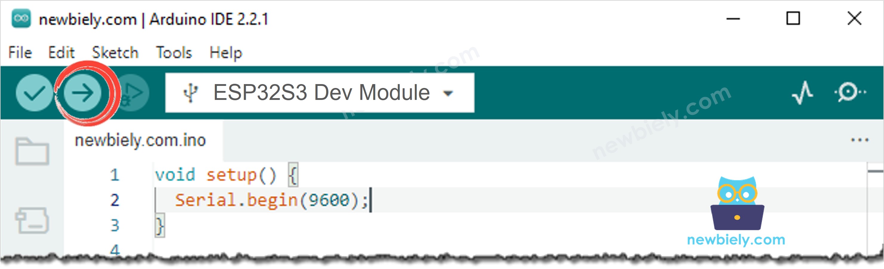
- Open the Serial Monitor at 115200 baud.
- Shine a bright light directly onto the light sensor and observe the LED turn off.
- Cover the light sensor with your hand to block the light and observe the LED turn on.
- Check the Serial Monitor to see the live analog readings printed in real time.
- Pro Tip: Try adjusting the threshold value in the code to fine-tune the trigger point for your room's ambient light conditions — print the raw ADC reading to the Serial Monitor first to determine the best threshold before hardcoding it.
Serial Monitor Output
The following Serial Monitor output shows the ESP32 S3 reading analog data from the light sensor in real time. Each line displays the current ADC value and the corresponding LED state triggered by the light threshold.
Application and Project Ideas
Once you can trigger an LED from a light sensor reading on the ESP32 S3, you can extend this pattern to a wide range of light-sensitive automation projects.
- Automatic night light: Turn on a room light or LED strip automatically when ambient light drops below a threshold at dusk or when a room is darkened.
- Daylight-controlled relay: Switch a relay (and therefore a mains-powered lamp or appliance) based on natural light levels instead of a manual switch.
- Greenhouse lighting controller: Maintain a minimum light level for plants by activating grow lights whenever the sensor detects insufficient natural light.
- Security lighting: Trigger bright LEDs or a camera when an area suddenly becomes dark, such as when a light is switched off in a monitored zone.
- Solar charge monitor: Use the light sensor to detect whether sunlight is available and route the signal to a charging control circuit.
- Smart curtain controller: Combine the light sensor with a servo motor or stepper motor to open or close curtains automatically based on the time of day and brightness.
Video Tutorial
Watch the step-by-step video walkthrough for this ESP32 S3 project below.
Challenge Yourself
Now that you can control an LED with a light sensor on the ESP32 S3, try these progressively challenging extensions to deepen your understanding and build more capable ambient-light detection systems.
- Beginner: Modify the threshold value in the code and observe how it changes the light level at which the LED switches on, then print a message to the Serial Monitor confirming the active threshold.
- Beginner: Add a second LED wired to a different GPIO pin and make it light up at a different (higher ADC value) threshold, so you have two light zones with separate visual indicators.
- Intermediate: Replace the simple on/off LED behaviour with PWM brightness control so the LED gradually brightens as the environment gets darker and dims as it gets brighter.
- Intermediate: Add an I2C OLED screen to display the live ADC reading and LED state in a formatted readout, removing the dependency on the Serial Monitor.
- Advanced: Store a configurable threshold value in ESP32 S3 non-volatile storage (Preferences library) so the setting persists across power cycles without re-uploading code.
- Advanced: Stream the light sensor readings over WiFi to a simple web page served by the ESP32 S3, and control the detection threshold remotely from a browser slider.