
ESP32 S3 Camera - Save Battery with Deep Sleep
All the other camera projects need a USB cable all the time. This tutorial is different. The ESP32 S3 sleeps and uses almost no power. When the motion sensor sees somebody, the board wakes up, takes a photo, saves it to the microSD card, and goes back to sleep. Because the board is awake for only about two seconds at a time, it uses very little power, so you can run it from a battery and put the camera at a gate, in a garden, or on a parcel box.
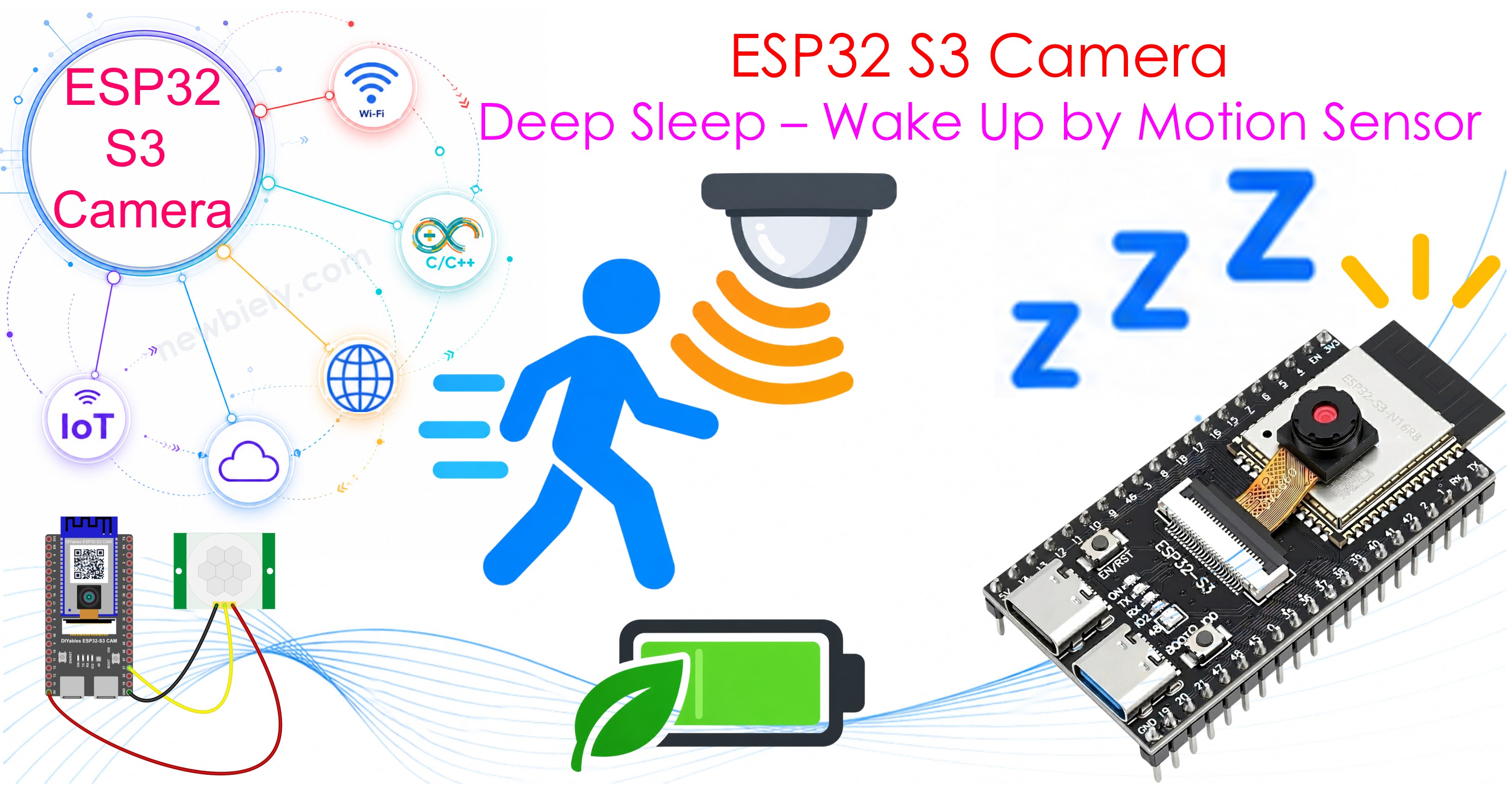
What you'll build:
- A camera that sleeps until something happens
- A photo saved to the microSD card on every wake up
- A counter that survives deep sleep, so the photo numbers never start again at 1
- A camera that works from a battery or a power bank, with no cable
Hardware Preparation
Or you can buy the following kits:
| 1 | × | DIYables Sensor Kit (18 sensors/displays) |
Additionally, some of these links are for products from our own brand, DIYables .
※ NOTE THAT:
The ESP32 S3 camera board has 40 pins, but the screw terminal block and the breakout board have 44 pins. They still work together. Put the camera board in the center of the 44-pin board, so 2 pins stay free on the left side and 2 pins stay free on the right side.
The screw terminal block lets you connect wires with a screwdriver, with no soldering. The breakout board gives you easy pin headers for a breadboard.
How It Works
All the other camera projects run in a circle: the board is awake all the time, and it asks again and again whether something happened. That is easy, but it uses power all day for nothing.
This project turns the idea around. The board sleeps, and the sensor wakes it up.
Here is the whole life of the camera:
| Step | What happens | How long | Power |
|---|---|---|---|
| 1 | The board sleeps. Only one small part inside it watches one pin. | Hours, or days | Almost none |
| 2 | Somebody walks past. The PIR sensor pulls GPIO21 HIGH. | At once | None, the sensor is not the board |
| 3 | That HIGH wakes the board. It starts again from the beginning, like after a RESET. | About 1 second | Full |
| 4 | The camera and the card start. The board takes a photo and writes it to the card. | About 1 second | Full |
| 5 | The board switches the camera and the card off, and goes back to sleep. | At once | Back to almost none |
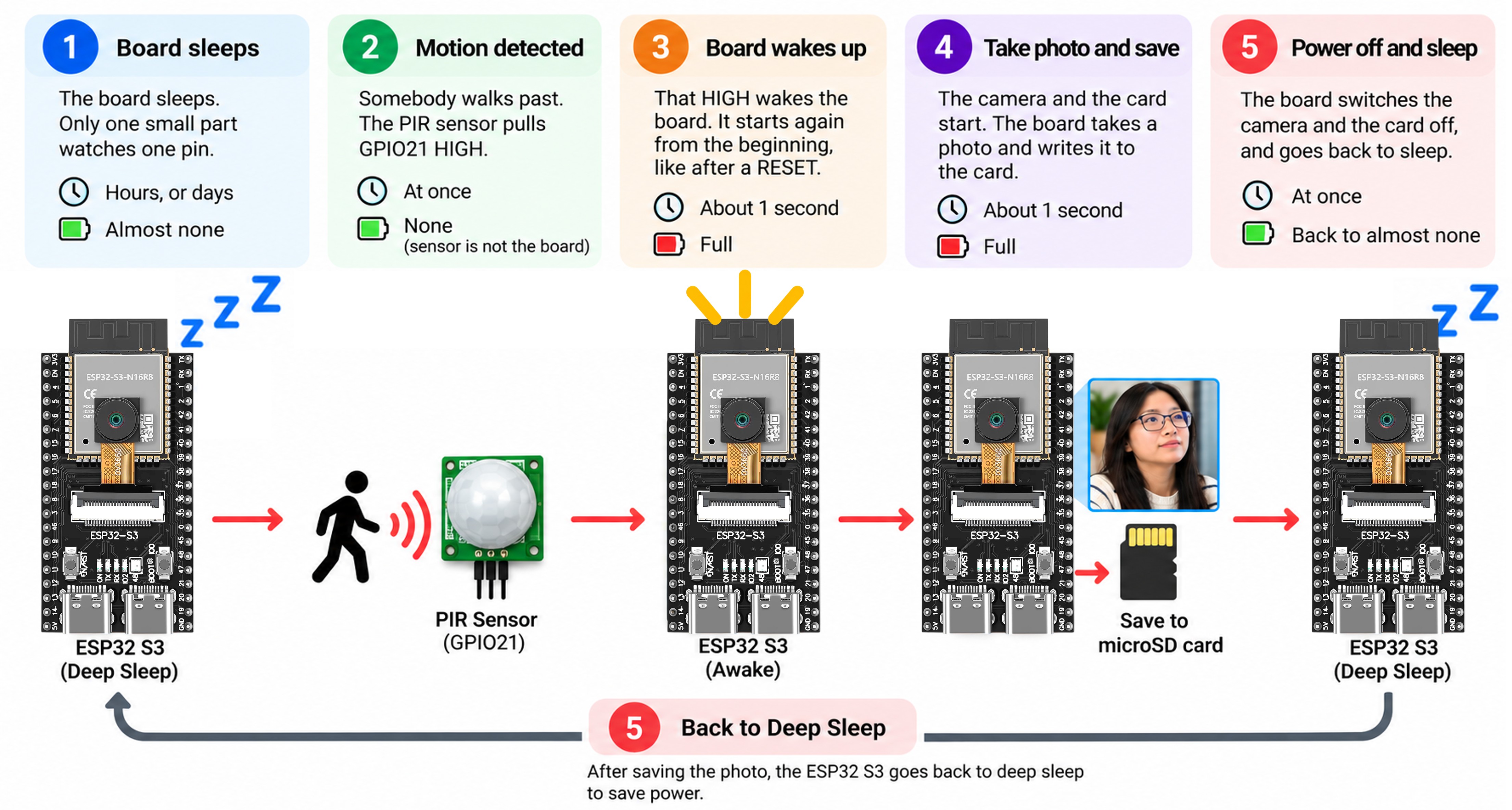
So the board is awake for only about two seconds for every visitor. All the rest of the time it is asleep. That is the whole trick, and it is why this camera can work with no cable.
※ NOTE THAT:
The PIR sensor never sleeps. It watches the room all the time, and it uses only a very small current to do it. The sensor is the part that decides when the board is needed.
Three Things Make It Work
| What | Why it is needed |
|---|---|
| esp_sleep_enable_ext0_wakeup() | Tells the board which pin may wake it, and at which level |
| RTC_DATA_ATTR | Keeps the photo counter alive during sleep. Normal variables lose their value. |
| esp_camera_deinit() and SD_MMC.end() | Switch the camera and the card off, so they use nothing during sleep |
Each of these is explained below.
Overview of Deep Sleep
Deep sleep switches off almost everything inside the ESP32 S3: the two processors, the WiFi, and the memory. Only one very small part stays awake, and its only job is to watch one pin.
| State | What is running | Current it uses |
|---|---|---|
| Normal, WiFi on | Everything | about 150 mA |
| Normal, WiFi off | Two processors | about 40 mA |
| Deep sleep | Almost nothing | less than 1 mA |
※ NOTE THAT:
These numbers are a guide, not a promise. Your board, your sensor and your power bank all change the result. Many power banks also switch themselves off when the current is very small, which is the most common problem in battery projects.
The Board Starts Again Every Time
This is the part that surprises everybody: after deep sleep, the board does not continue where it stopped. It starts again from the very beginning, exactly like after a RESET. setup() runs again, and loop() never runs at all.
So the whole program lives inside setup():
How to Remember Something During Sleep
Normal variables lose their value during deep sleep. Variables marked RTC_DATA_ATTR do not, because they live in the small part that stays awake:
※ NOTE THAT:
RTC_DATA_ATTR keeps the value through deep sleep, but not through a power cut or a RESET. The code also checks the card for free file names, so no photo is ever written over.
Waking Up on a Pin
ext0 wakes the board when one pin reaches a level you choose. The number 1 means "wake when the pin is HIGH":
※ NOTE THAT:
Only the pins GPIO0 to GPIO21 can wake the ESP32 S3 from deep sleep. They are called RTC pins. GPIO21 is one of them, so it works. A pin like GPIO40 would never wake the board.
Overview of PIR Motion Sensor
A PIR motion sensor sees the heat of a human body. Its OUT pin goes HIGH when something warm moves in front of it, and that HIGH is what wakes the ESP32 S3.
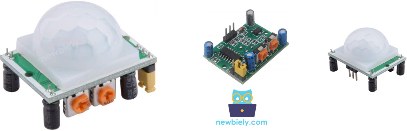
The sensor has two small orange screws. Turn the time delay screw all the way to the left, so the output stays HIGH for only about 3 seconds. For more detail, see the ESP32 S3 - Motion Sensor tutorial.
※ NOTE THAT:
The PIR sensor itself never sleeps. It uses about 50 µA, which is very little, and it must stay awake, because it is the part that wakes the board.
Wiring Diagram between PIR Motion Sensor and ESP32 S3
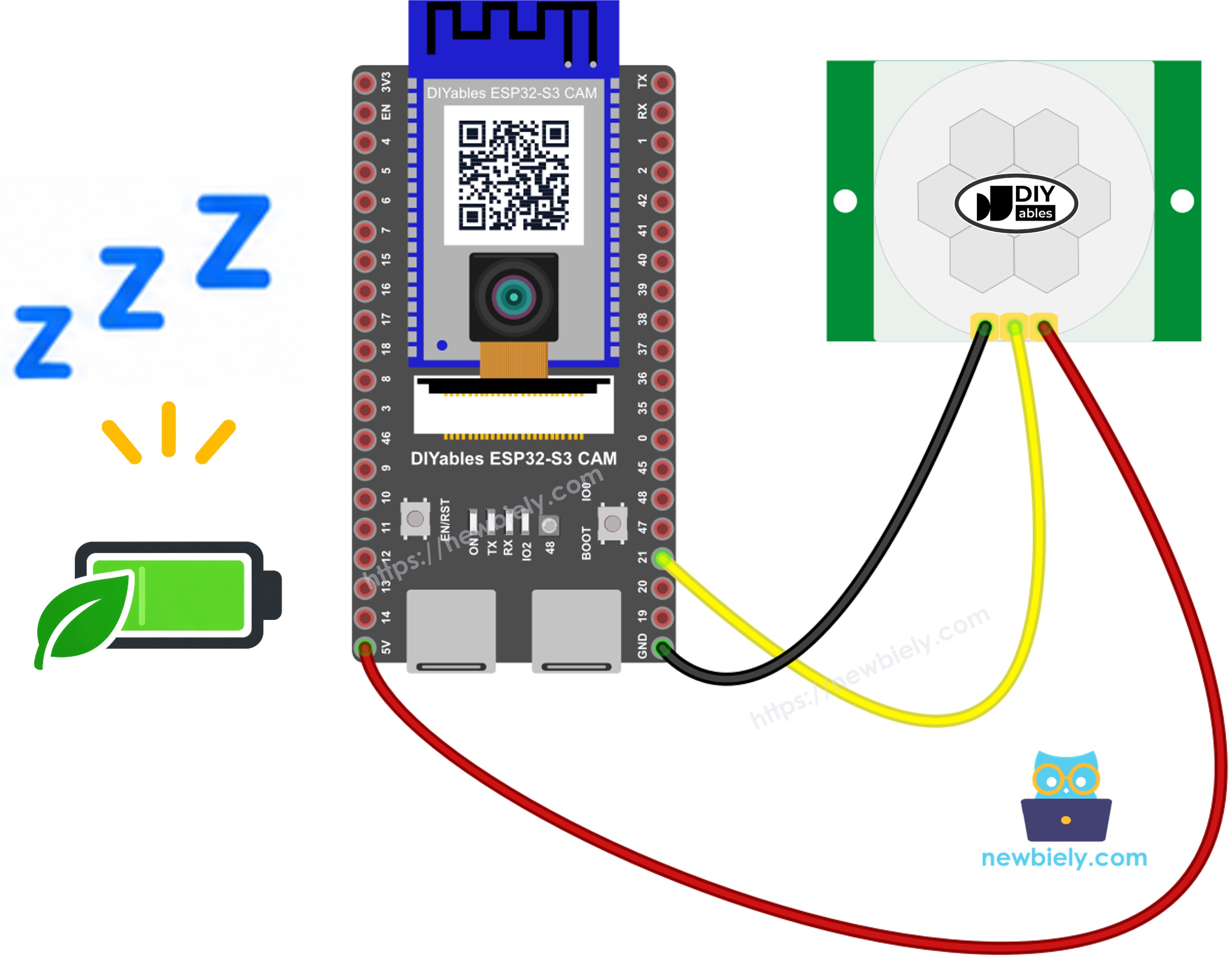
This image is created using Fritzing. Click to enlarge image
| PIR Sensor Pin | ESP32 S3 Pin |
|---|---|
| VCC | 5V |
| GND | GND |
| OUT | GPIO21 |
Then put the microSD card into the slot on the board.
Safety Notes
The PIR sensor needs 5V on its VCC pin, not 3.3V. Its OUT pin gives 3.3V, which is correct for the ESP32 S3.
The OUT pin must go to GPIO21, because only GPIO0 to GPIO21 can wake the board from deep sleep.
Arduino IDE Settings for ESP32 S3 Camera
The camera does not work with the default settings of the Arduino IDE. You must change some items in the Tools menu before you upload the code.
| Tools Menu Item | Select This |
|---|---|
| Board | ESP32S3 Dev Module |
| Flash Size | 16MB (128Mb) |
| PSRAM | OPI PSRAM |
| Partition Scheme | Huge APP (3MB No OTA/1MB SPIFFS) |
| CPU Frequency | 240MHz (WiFi) |
| USB Mode | Hardware CDC and JTAG |
| Upload Mode | UART0 / Hardware CDC |
| Upload Speed | 921600 |
| USB CDC On Boot | Enabled |
How To Program the Sleeping Camera
- Find out why the board woke up. This is useful, because the first start is not a wake up.
- Give the camera a moment. The first pictures after a start are always too dark, because the camera has not set the light yet.
※ NOTE THAT:
This is the most common mistake in deep sleep cameras: the photo is black. The camera needs about half a second of light before the first good picture.
- Switch the camera and the card off before sleeping, so they use no power.
- Hold the pin down during sleep, so a floating pin cannot wake the board by itself.
※ NOTE THAT:
Without this, an unconnected pin picks up electrical noise, the board wakes up hundreds of times, and the battery is empty in one night.
- Go to sleep. Nothing after this line ever runs.
ESP32 S3 Code
The photos are named wake_00001.jpg, wake_00002.jpg, and so on. The counter lives in RTC_DATA_ATTR, so it keeps counting through every sleep.
Detailed Instructions
- New to ESP32 S3? Complete our Getting Started with ESP32 S3 guide first.
- Format your microSD card as FAT32 on your computer.
- Unplug the USB cable. Put the card into the slot, and wire the PIR sensor as in the table above.
- Copy the above code and paste it into the Arduino IDE.
- Change the settings in the Tools menu. See the table above.
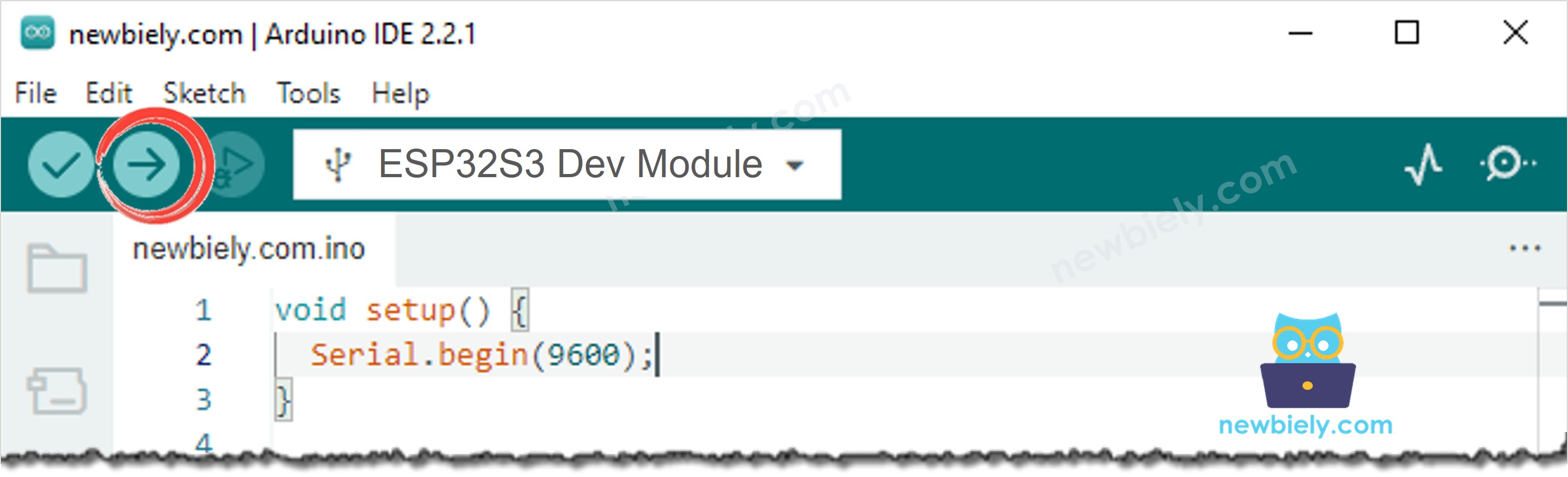
- Compile and upload the code to the ESP32 S3 board by clicking the Upload button in Arduino IDE.
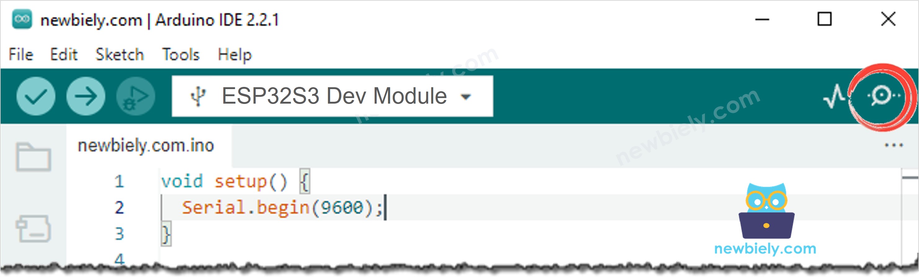
- Open the Serial Monitor in Arduino IDE.
- Press the RESET button one time. The board takes one photo and sleeps.
- Wave your hand in front of the sensor. The board wakes up, you see a new line, and it sleeps again.
- When you are happy, unplug the USB cable and use a power bank instead.
- Pro Tip: Keep the Serial Monitor open while you test. It is the only way to see that the board really wakes up.
Serial Monitor
Every wake up prints two lines. The following readings were captured in 2026:
※ NOTE THAT:
The board is awake for only about 2 seconds each time. All the rest of the time it sleeps and uses almost nothing. That is the whole idea of this project.
How To Save Even More Power
The battery is used in two ways: a very small amount all the time while the board sleeps, and a much larger amount during the two seconds of each photo. So there are only two ways to use less:
| What to do | How | Why it helps |
|---|---|---|
| Stay awake for less time | Use a smaller FRAME_SIZE, for example FRAMESIZE_VGA | A smaller photo is taken and written faster |
| Wake up fewer times | Turn the sensitivity screw of the sensor down, and point it away from the street | Every wake up costs much more than an hour of sleeping |
Watch the Serial Monitor to see how long your board is really awake. The time between Wake up number ... and Going to sleep. Bye. is the part that costs power. Everything between two wake ups is almost free.
※ NOTE THAT:
We do not say here how many days or weeks a battery lasts, because it depends on too many things: which battery, how old it is, how cold the night is, how often somebody walks past, and how much your own power bank uses by itself. Measure it in your own place, with your own battery.
※ NOTE THAT:
Many power banks switch themselves off when a device takes almost no current, which is exactly what deep sleep does. If your camera stops during the night, this is usually the reason. Use a power bank that supports "low current mode", or use a battery with a proper holder.
Troubleshooting
The board never wakes up.
- The OUT pin of the sensor must be on GPIO21. A pin above GPIO21 cannot wake the board.
- Check that the sensor has 5V, not 3.3V.
- Wait one minute after the first start. The PIR sensor is still warming up.
The board wakes up again and again with nothing in front of it.
- The sensor is too sensitive. Turn the sensitivity screw a little to the left.
- Point the sensor away from windows, heaters and air conditioners.
Every photo is black or very dark.
The camera did not have time to set the light. Increase WARMUP_TIME from 400 to 800, and change the loop from 2 to 3 pictures.
The photos stop after some hours on a power bank.
The power bank switched itself off, because deep sleep takes too little current for it. Use a power bank with low current mode, or a battery.
The Serial Monitor loses the connection after every sleep.
This is normal on the native USB port, because the board disappears when it sleeps. Use the UART port for testing, and set USB CDC On Boot to Disabled.
The numbers start again at 1 after a power cut.
RTC_DATA_ATTR does not survive a power cut. This is not a problem: the code looks for the first free name on the card, so no photo is ever written over.
Applications
A camera that needs no cable can go where the other projects cannot. Here are practical projects you can build with this code:
- Trail and wildlife camera: Put it in a forest or a field with no power at all.
- Parcel box camera: A small battery inside the box, and no cable through the wall.
- Garden gate watcher: Watch a gate far away from the house, with no cable to lay.
- Bicycle and garage camera: Keep a photo of everybody who comes near, with no wiring work.
- Holiday home camera: Leave it in an empty house while you are away.
- Farm and barn camera: Watch animals or a machine far from any socket.
- Building site camera: Move it every day, because there is nothing to plug in.
- Beehive watcher: Watch the hive without a cable across the garden.
- Car camera: Take a photo when somebody comes near your parked car.
- Temporary security camera: Put it anywhere for a while, then take it away again.
Video Tutorial
Watch the step-by-step video walkthrough for this ESP32 S3 project below.
Challenges
- Beginner: Change the photo size from FRAMESIZE_SVGA to FRAMESIZE_UXGA and see how much longer the board stays awake.
- Intermediate: Add a timer wake up as well, so the board also takes one photo every hour, even without movement. Use esp_sleep_enable_timer_wakeup().
- Advanced: Connect WiFi after the wake up and send the photo to Telegram, then sleep. Watch the Serial Monitor and see how much longer the board must stay awake.