
ESP32 S3 - Motion Sensor - Piezo Buzzer
This tutorial shows you how to connect an HC-SR501 motion sensor and a piezo buzzer to an ESP32 S3 board and program it to react to movement with sound. You will build two practical projects: one that plays a simple tone when motion is detected, and another that plays a full melody triggered by movement.
What you'll build:
- A motion-triggered simple sound alert using the ESP32 S3 and HC-SR501 sensor
- A motion-triggered melody player using a passive piezo buzzer
- Automatic sound stop when no motion is detected
- A foundation for real-world security and notification systems
Hardware Preparation
Or you can buy the following kits:
| 1 | × | DIYables ESP32 S3 Starter Kit (ESP32 S3 included) | |
| 1 | × | DIYables Sensor Kit (18 sensors/displays) |
Additionally, some of these links are for products from our own brand, DIYables .
Overview of Piezo Buzzer and Motion Sensor
The HC-SR501 is a passive infrared (PIR) motion sensor that detects movement by measuring infrared radiation emitted from warm bodies such as humans or animals. The piezo buzzer converts electrical signals into audible tones, making it an ideal output device for motion-triggered alerts. Together, these two components form the core of many practical security and notification systems.
We have specific tutorials about piezo buzzer and motion sensor. Each tutorial contains detailed information and step-by-step instructions about hardware pinout, working principle, wiring connection to ESP32 S3, and ESP32 S3 code. Learn more about them at the following links:
Key Specifications
- HC-SR501 operating voltage: 5V–20V DC
- HC-SR501 detection range: up to 7 meters (adjustable)
- HC-SR501 detection angle: up to 120°
- Active piezo buzzer voltage: 3–24V DC
- Passive piezo buzzer: requires PWM signal to produce tones and melodies
Please note that this tutorial uses a 3–5V buzzer, but you can adapt it for a 12V buzzer. You can learn more about buzzer options in the ESP32 S3 - Buzzer tutorial.
Wiring Diagram
Connect the HC-SR501 motion sensor and piezo buzzer to your ESP32 S3 following the diagrams below, making sure to observe proper polarity for both components.
The wiring diagram with power supply from USB cable
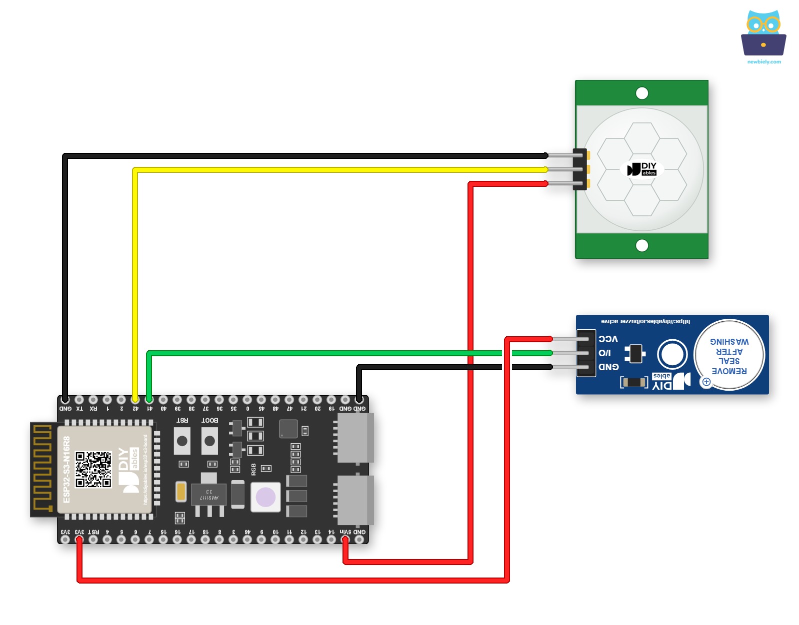
This image is created using Fritzing. Click to enlarge image
Loose wires are a common cause of strange bugs. To do that, mount the ESP32 S3 on a Screw Terminal Block for ESP32 S3. This is how it looks with the screw terminal board:
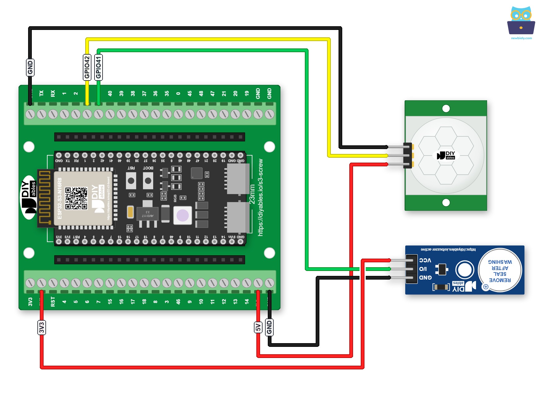
This image is created using Fritzing. Click to enlarge image
Here is the same circuit with a GPIO Breakout Board for ESP32 S3, which breaks out every GPIO to pin headers:
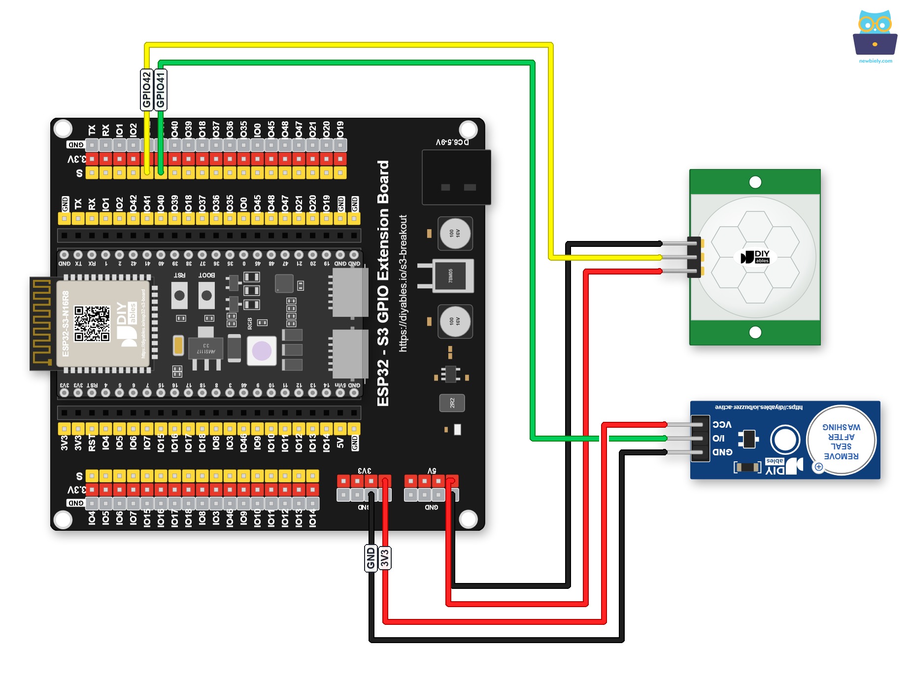
This image is created using Fritzing. Click to enlarge image
The wiring diagram with power supply from 5V adapter
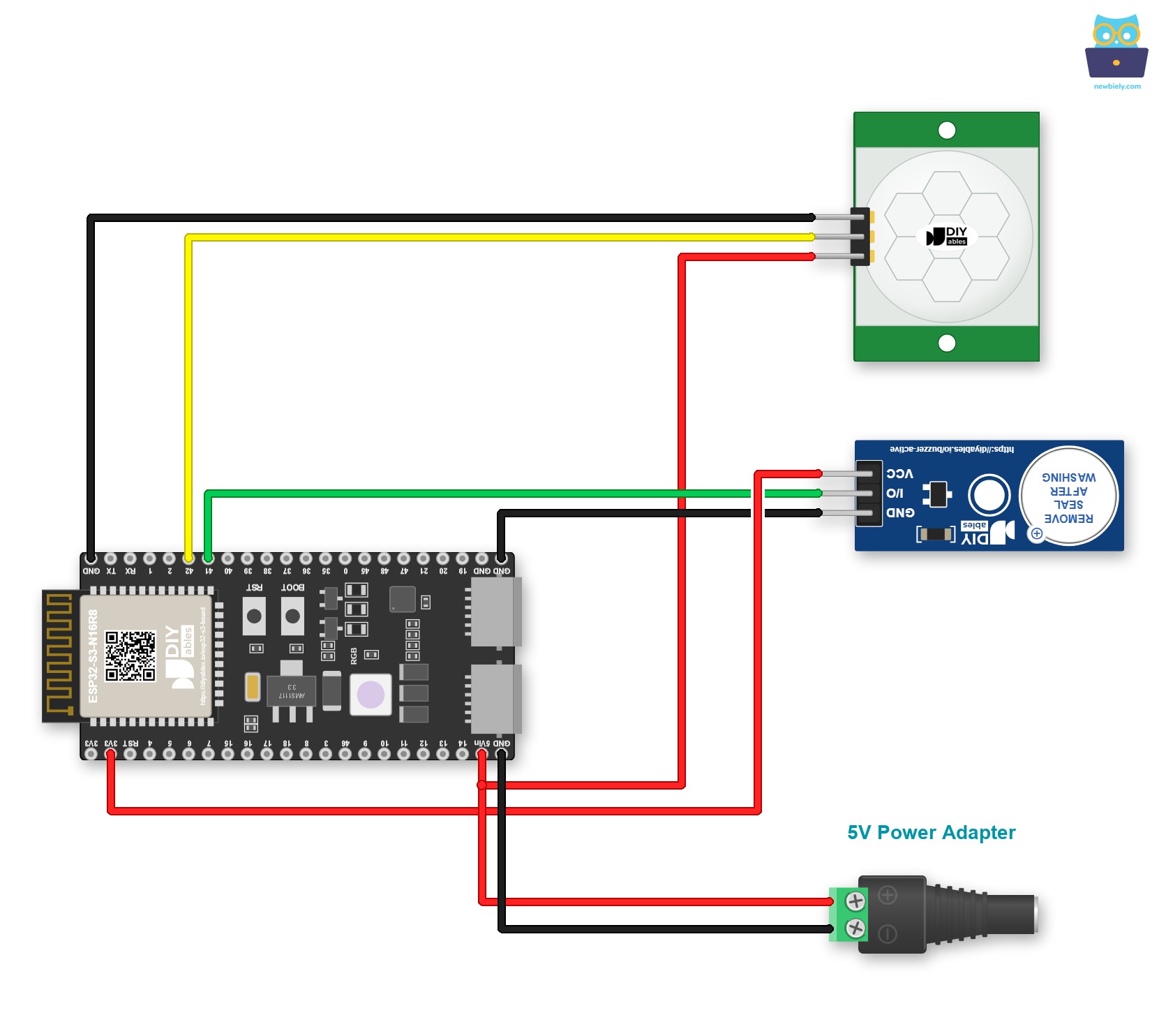
This image is created using Fritzing. Click to enlarge image
Jumper wires can come loose when you move the project. The ESP32 S3 fits a Screw Terminal Block for ESP32 S3, which turns every pin into a screw terminal. See the diagram below for the screw terminal version.
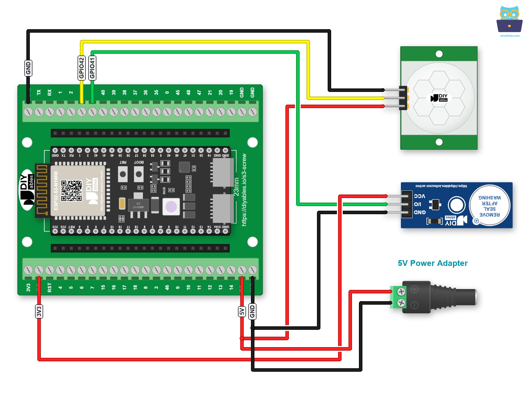
This image is created using Fritzing. Click to enlarge image
Another choice is a GPIO Breakout Board for ESP32 S3. Each GPIO has a signal pin with 3.3V and GND pins next to it, as shown below:
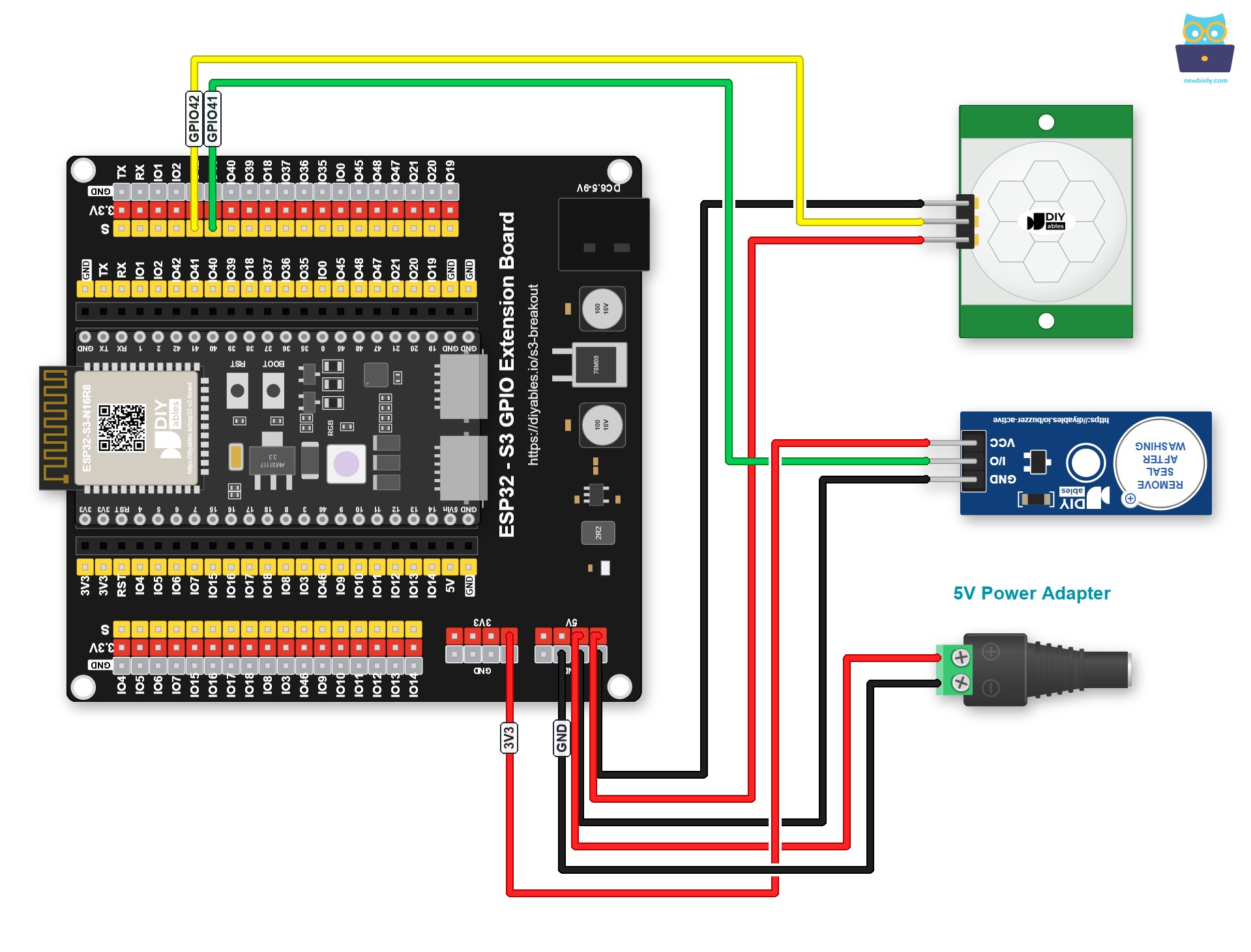
This image is created using Fritzing. Click to enlarge image
Safety Notes
The HC-SR501 sensor requires 5V–20V on its VCC pin, while the ESP32 S3 GPIO pins operate at 3.3V logic levels. The sensor's output signal is typically 3.3V, which is compatible with ESP32 S3 inputs. Always double-check that the buzzer's positive terminal connects to the designated GPIO pin and the negative terminal connects to GND to avoid reversed polarity.
Initial Setting
| Detection Range Adjuster | Fully screw it in the clockwise direction. |
| Time Delay Adjuster | Fully screw it in the anti-clockwise direction. |
| Repeat Trigger Selector | Put jumper like the below image. |
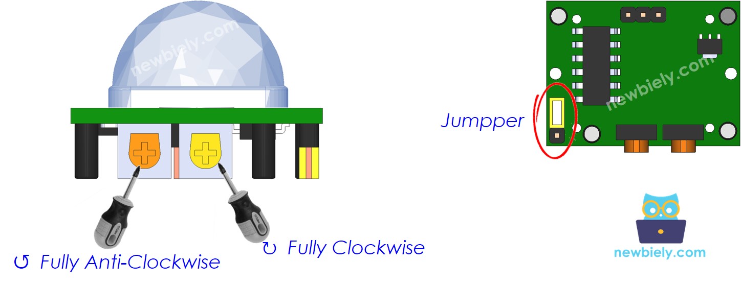
ESP32 S3 Code - Simple Sound
The following code programs the ESP32 S3 to monitor the HC-SR501 motion sensor and immediately activate the piezo buzzer whenever motion is detected. When no motion is present, the buzzer remains silent, creating a straightforward audible alert system. Upload this sketch to your ESP32 S3 and test it by moving your hand in front of the sensor.
Detailed Instructions
- New to ESP32 S3? Complete our Getting Started with ESP32 S3 guide first.
- Do the wiring as shown in the diagram above.
- Connect the ESP32 S3 board to your PC via a USB Type-C cable.
- Open Arduino IDE on your PC.
- Select the right ESP32 S3 board and COM port.
- Copy the above code and paste it to Arduino IDE.
- Compile and upload the code to the ESP32 S3 board by clicking the Upload button in Arduino IDE.
- Move your hand in front of the sensor.
- Listen to the piezo buzzer's sound.
- Pro Tip: Adjust the HC-SR501's sensitivity and delay potentiometers to fine-tune detection range and how long the buzzer sounds after motion stops.
Line-by-line Code Explanation
The above ESP32 S3 code contains line-by-line explanation. Please read the comments in the code!
ESP32 S3 Code - Melody
The following code extends the project by playing a full musical melody through a passive piezo buzzer whenever the HC-SR501 detects motion. This approach uses PWM frequency control to generate distinct musical notes, and playback stops automatically when no motion is detected. Follow the steps below to set up the pitches header file required by this sketch.
Detailed Instructions
- New to ESP32 S3? Complete our Getting Started with ESP32 S3 guide first.
- Copy the above code and paste it to Arduino IDE.
- Create the pitches.h file in Arduino IDE by:
- Either click on the button just below the serial monitor icon and choose New Tab, or use Ctrl+Shift+N keys.
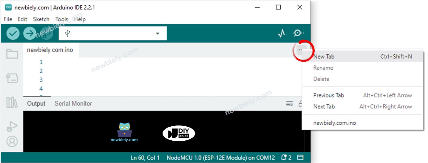
- Give the file's name pitches.h and click the OK button.
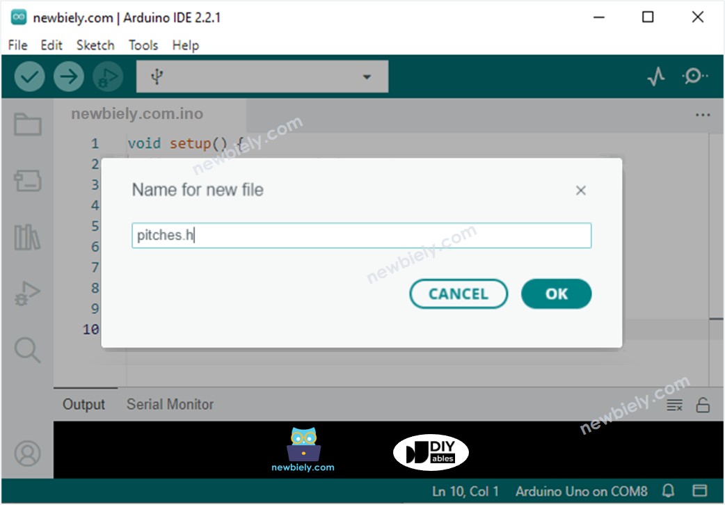
- Copy the below code and paste it to the created pitches.h file.
- Compile and upload the code to the ESP32 S3 board by clicking the Upload button in Arduino IDE.
- Move your hand in front of the sensor.
- Listen to the piezo buzzer's melody.
- Pro Tip: Try swapping the melody array with your own note sequence in the sketch to personalize the alert tune.
Line-by-line Code Explanation
The above ESP32 S3 code contains line-by-line explanation. Please read the comments in the code!
Serial Monitor Output
Open the Serial Monitor in Arduino IDE (set baud rate to 9600) after uploading the code. You should see output similar to the following readings, with timestamps reflecting the moments motion is detected and cleared.
Applications
Motion-triggered buzzer systems built with the ESP32 S3 are practical and versatile components for a wide range of real-world projects across home, office, and industrial environments.
- Home Security Alert: Sound an alarm when an intruder enters a room or restricted area.
- Doorbell System: Automatically beep when someone approaches a door or entrance.
- Child Safety Monitor: Alert parents when a child enters a hazardous area such as a staircase or pool zone.
- Retail Customer Greeter: Play a welcome tone when a customer walks into a shop.
- Wildlife Detection: Trigger a buzzer when animals approach a garden or protected area.
- Office Occupancy Indicator: Sound an alert when someone enters an unoccupied meeting room.
Video Tutorial
Watch the step-by-step video walkthrough for this ESP32 S3 project below.
Challenges
These challenges are designed to push your understanding of the ESP32 S3, motion sensing, and buzzer control beyond the basics presented in this tutorial.
- Beginner: Modify the code so the buzzer beeps three times (short pulses) instead of sounding continuously when motion is detected.
- Intermediate: Add an LED indicator alongside the buzzer so both light and sound activate together when motion is detected, and both turn off when motion stops.
- Advanced: Implement a time-based mute feature using the ESP32 S3's internal clock so the buzzer is disabled during nighttime hours (e.g., 10 PM to 7 AM) even when motion is detected.