
ESP32 S3 - 2-Channel Relay Module
Learn how to control two high-voltage devices simultaneously using an ESP32 S3 and a 2-channel relay module. This beginner-friendly tutorial covers everything you need to switch pumps, fans, lights, and other appliances with your ESP32 S3 microcontroller.
What you'll build:
- A dual-relay control system using the ESP32 S3 WROOM N16R8
- Independent switching of two high-voltage devices via GPIO pins
- Real-time relay state feedback through the Serial Monitor
- A foundation for home automation and IoT projects
https://newbiely.com/images/cover/esp32-s3-2-channel-relay-module.jpg
Hardware Preparation
Or you can buy the following kits:
| 1 | × | DIYables ESP32 S3 Starter Kit (ESP32 S3 included) | |
| 1 | × | DIYables Sensor Kit (18 sensors/displays) |
Additionally, some of these links are for products from our own brand, DIYables .
Overview of 2-Channel Relay Module
A 2-channel relay module is an electromechanical switching board that allows your ESP32 S3 to control two separate high-voltage circuits using low-voltage GPIO signals. Each relay channel operates independently, making this module ideal for applications that need to switch two different loads — such as a pump and a fan — with a single compact board. The built-in optocouplers electrically isolate the ESP32 S3 from the high-voltage side, protecting your microcontroller from voltage spikes and interference.
Key Specifications
- Controls two independent high-voltage devices (AC or DC)
- Operates with 5V power supply
- Accepts 3.3V or 5V control signals
- Built-in optocouplers for safety and isolation
- LED indicators show relay status
- Supports both low-level and high-level trigger modes
- Maximum load: typically 10A at 250VAC or 10A at 30VDC per channel
- Perfect for beginners learning home automation
Pinout
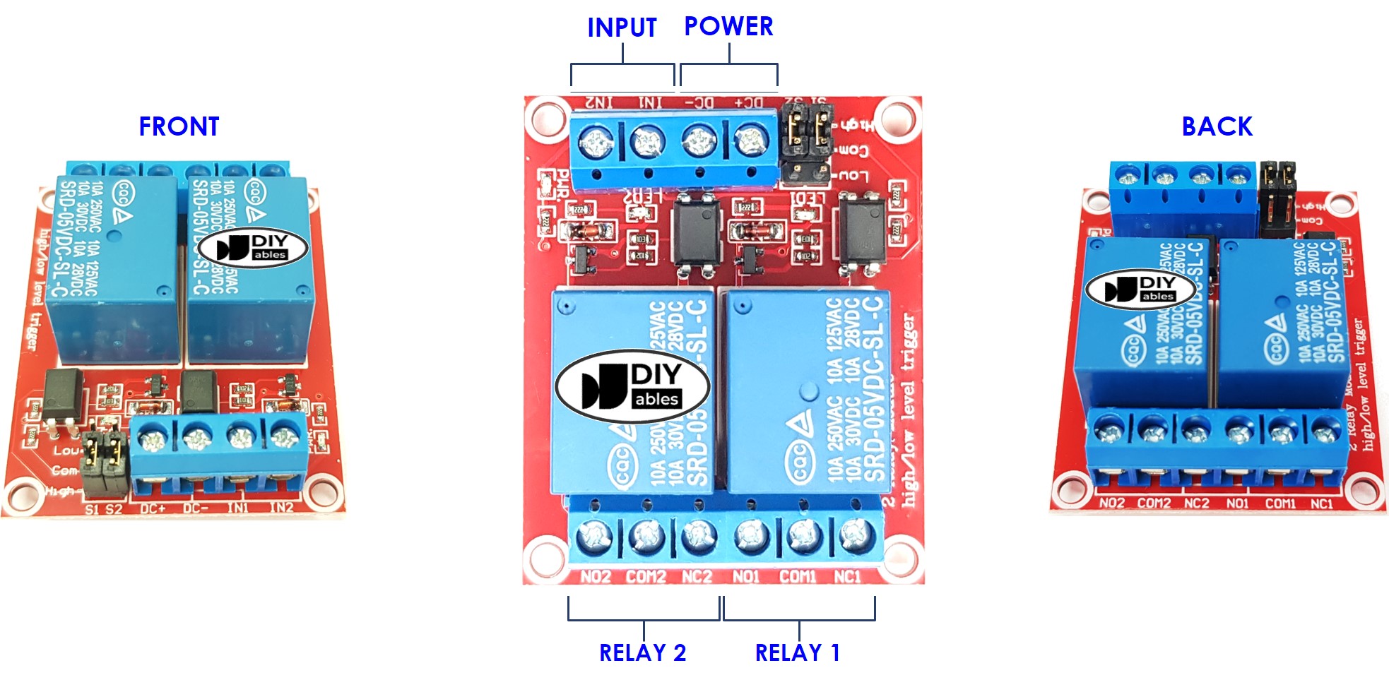
The 2-channel relay module exposes three categories of pins: power supply, control signal inputs, and high-voltage output terminals for each relay channel.
- DC+: Connect to 5V power supply
- DC-: Connect to GND of power supply AND GND of ESP32 S3
- IN1: Control signal from ESP32 S3 for relay 1
- IN2: Control signal from ESP32 S3 for relay 2
- COM1: Common terminal for device 1
- NO1: Normally open terminal (connects when relay 1 activated)
- NC1: Normally closed terminal (disconnects when relay 1 activated)
- COM2: Common terminal for device 2
- NO2: Normally open terminal (connects when relay 2 activated)
- NC2: Normally closed terminal (disconnects when relay 2 activated)
- Two jumpers for selecting trigger mode (low-level or high-level) per relay
- Two LED indicators showing each relay's status
For detailed information about relay basics, including normally closed vs normally open connections and low-level vs high-level triggering, check out our ESP32 S3 - Relay tutorial.
Wiring Diagram
Connect your ESP32 S3 to the 2-channel relay module following this wiring diagram. The IN1 and IN2 pins connect to GPIO pins on the ESP32 S3, while the DC+ and DC- pins provide the 5V power the relay module needs to operate its coils.
Safety Notes
When working with high-voltage devices, always disconnect all power before making any wiring changes. If both devices share the same voltage (for example, both run at 12V), you can use a single power adapter for both; if they require different voltages, use separate power adapters and ensure all GND connections are tied together with the ESP32 S3 ground.
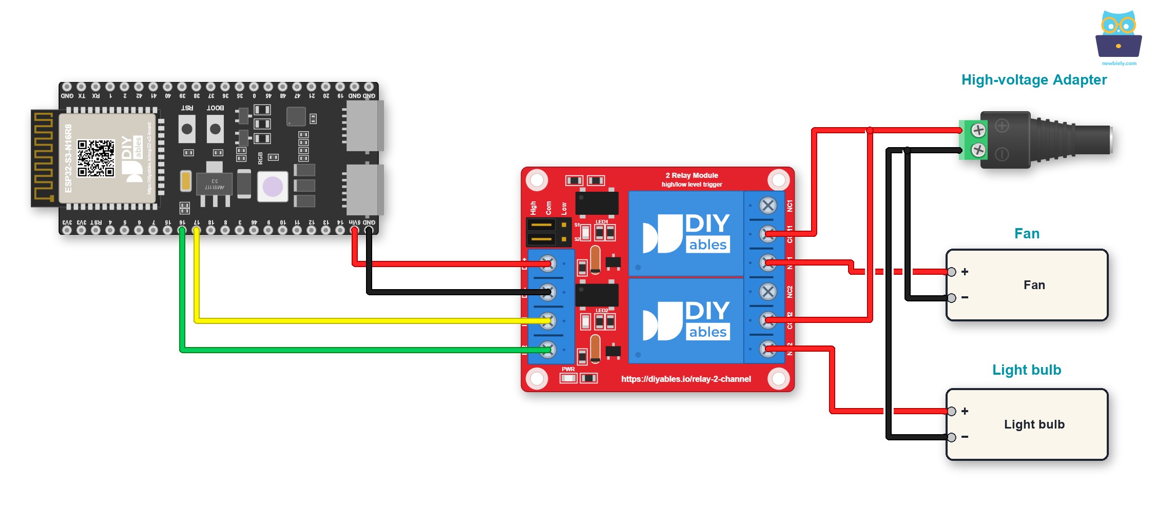
This image is created using Fritzing. Click to enlarge image
| 2-Channel Relay Pin | ESP32 S3 Pin |
|---|---|
| DC+ | 5V |
| DC- | GND |
| IN1 | GPIO17 |
| IN2 | GPIO16 |
Jumper wires are good for a quick test, but not for a final build. Simply plug the ESP32 S3 into a Screw Terminal Block for ESP32 S3. The wiring stays the same. Only the wires now go to the screw terminals, as shown below.
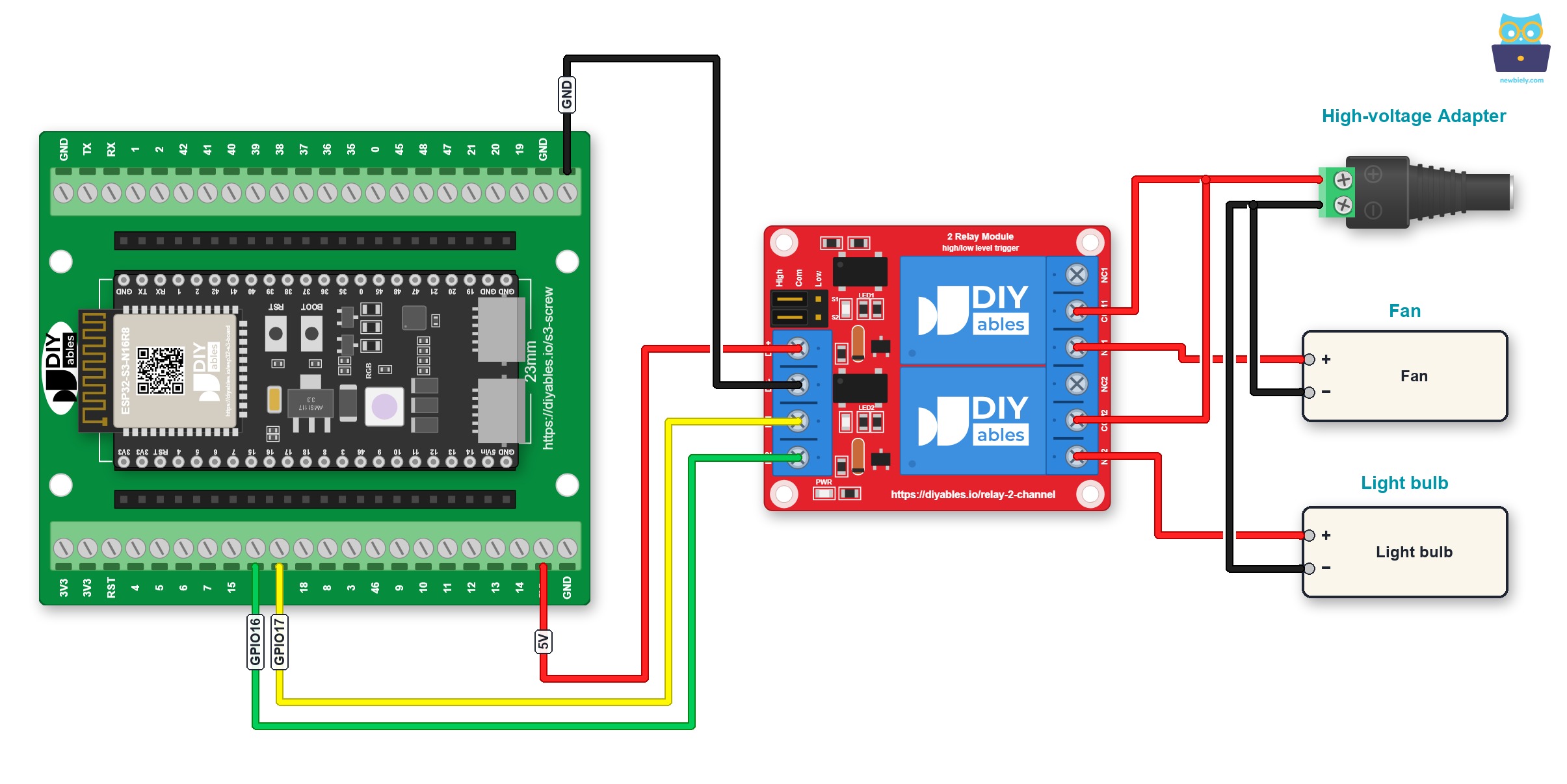
This image is created using Fritzing. Click to enlarge image
Here is the same circuit with a GPIO Breakout Board for ESP32 S3, which breaks out every GPIO to pin headers:
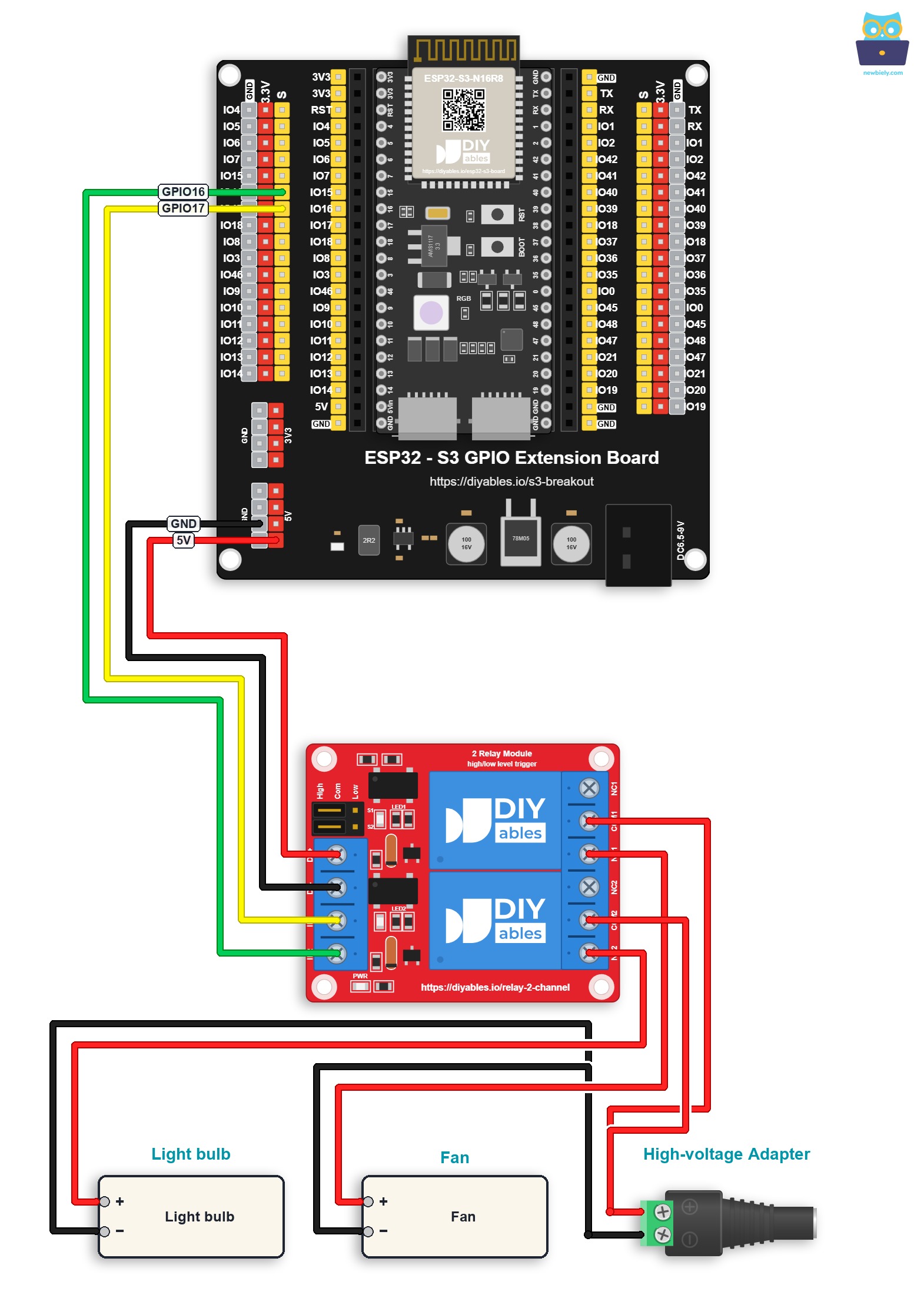
This image is created using Fritzing. Click to enlarge image
※ NOTE THAT:
Power considerations: If both devices require the same voltage (e.g., both 12V), use one power adapter for both. If devices need different voltages, use separate power adapters for each device. Always connect the GND of all power supplies together with the ESP32 S3 GND.
※ NOTE THAT:
Safety warning: When working with high-voltage devices, always disconnect power before wiring. Double-check all connections before applying power to prevent short circuits or damage.
How To Program For 2-Channel Relay Module
Programming the 2-channel relay module with the ESP32 S3 requires only a few lines of Arduino code. The following code demonstrates how to configure two GPIO pins as digital outputs and toggle the relay states with delays to verify the wiring and observe relay switching behavior. Each relay channel is controlled independently using digitalWrite(), giving you full flexibility over timing and sequencing.
Initialize relay pins:
Control relay states:
ESP32 S3 Code
Detailed Instructions
- New to ESP32 S3? Complete our Getting Started with ESP32 S3 guide first.
- Copy the code: Copy the code above to Arduino IDE.
- Select board: Choose ESP32 S3 from Tools > Board menu.
- Select port: Choose the correct COM port from Tools > Port menu.
- Upload: Click the Upload button to program your ESP32 S3.
- Listen: You should hear clicking sounds as relays switch on and off.
- Open Serial Monitor: Click the Serial Monitor icon (top-right) and set baud rate to 115200.
- Observe output: Watch the relay status messages appear every 2 seconds.
- Pro Tip: Use different delay times for relay 1 and relay 2 to create custom timing patterns for your automation projects.
Serial Monitor Output
Applications and Project Ideas
The ESP32 S3's wireless capabilities and processing power make it an excellent companion for a 2-channel relay module in a wide range of real-world automation projects:
- Smart home lighting: Control two different room lights or lamp circuits independently
- Garden automation: Manage a water pump and grow lights on separate schedules
- Garage door opener: Control door motor and interior lights simultaneously
- Aquarium controller: Operate filter pump and aquarium lighting system
- HVAC automation: Switch heating and cooling systems based on temperature sensors
- Security system: Control door locks and alarm sirens with smartphone or sensors
- Tutorial automation: Manage power tools and ventilation fans remotely
Video Tutorial
Watch the step-by-step video walkthrough for this ESP32 S3 project below.
Challenge Yourself
These challenges will help you build on the basic relay control skills from this tutorial and push your ESP32 S3 projects further:
- Beginner: Modify the code to turn relays on and off at different time intervals (e.g., relay 1 every 1 second, relay 2 every 3 seconds)
- Beginner: Add LED indicators on breadboard that mirror the relay states for visual feedback
- Intermediate: Create a web server that lets you control both relays from your phone's web browser
- Intermediate: Connect a DHT22 temperature sensor and automatically control a fan (relay 1) and heater (relay 2) based on temperature
- Advanced: Build a complete IoT home automation system using MQTT protocol to control relays from anywhere in the world
- Advanced: Implement scheduling functionality that stores on/off times in EEPROM for automatic daily device control