
Arduino Nano ESP32 - NTC Thermistor Temperature Sensor
In this guide, we will learn how to make a thermometer from the Arduino Nano ESP32 and a 10K NTC 3950 probe in a steel tube. The tube is small, sealed, and sits at the end of a thin cable. So you can lower it into a sous-vide pot, push it into a jar of fermenting kombucha, lay it on a fridge shelf, or stick it into the soil of a seed tray. In detail, we will learn:
- The job of each probe wire, and of the 10K resistor that ships with every probe.
- How three pins of the Nano ESP32 (3V3, A7 and GND) and that resistor form a voltage divider.
- How to get the A7 voltage in millivolts, work back to the thermistor's ohms, and then to Celsius and Fahrenheit.
- How the sketch spots a loose plug or a short, and shows a wiring hint rather than a false temperature.
Hardware Preparation
Or you can buy the following kits:
| 1 | × | DIYables Sensor Kit (18 sensors/displays) |
Additionally, some of these links are for products from our own brand, DIYables .
Overview of NTC Thermistor Temperature Sensor
Look closely at the probe and you find three parts. At one end is a round-tipped tube of stainless steel, 5mm across and 25mm long, with the thermistor sealed inside. In the middle is 0.5m of black cable with two wires. At the other end is a white JST XH2.54 plug with two holes. Nothing else: no small board, no chip, no LED. The DIYables set holds five of these probes plus five 10K resistors, one for each.
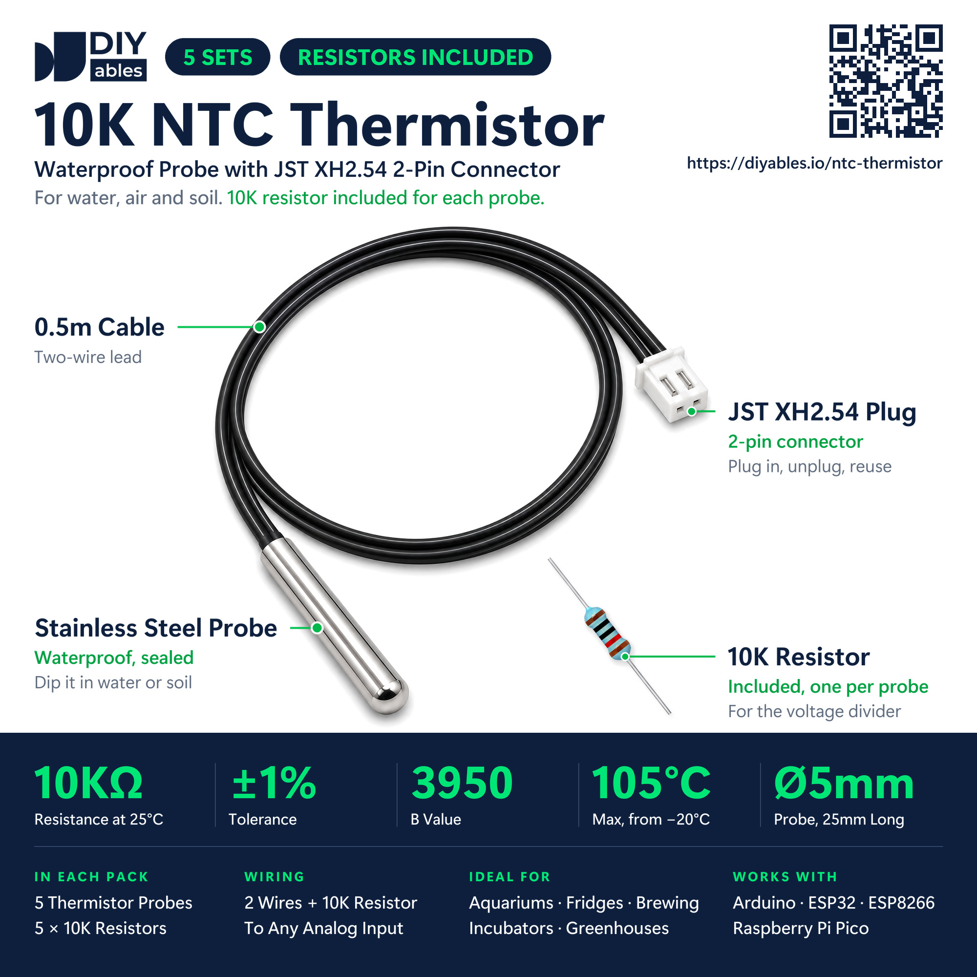
A male jumper wire slides straight into each of the two holes in the plug. Then:
- First wire: connect to the 3V3 pin of the Nano ESP32.
- Second wire: connect to A7. The 10K resistor also starts here and ends on GND.
You do not need to find out which wire is which. The steel tip holds only a resistor, and a resistor works the same in both directions.
| Waterproof NTC Probe | |
|---|---|
| Thermistor | NTC, 10kΩ ±1% at 25°C |
| Beta (B) constant | 3950 |
| Works from | -20°C up to 105°C |
| Tip | stainless steel, sealed, Ø5 x 25mm |
| Lead | 0.5m, 2 wires, either way round |
| Plug type | female JST XH2.54 with 2 holes |
| Insulation resistance | more than 100MΩ |
How the probe tells the temperature
A thermistor is a resistor that changes a lot with heat. In an NTC type, heat makes the number of ohms drop, and cold makes it climb. The ADC of the Nano ESP32 only understands volts, though. The 10K resistor fixes that. Thermistor on top (to 3V3) and resistor at the bottom (to GND) share the 3.3V between them, and A7 sits on the joint. As the tip heats up, the thermistor's share gets smaller, so A7 goes up. The sketch measures A7, works out the ohms, and turns the ohms into degrees. A few sample values with this exact circuit:
| Probe temperature | NTC resistance | A7 voltage (3V3 supply) |
|---|---|---|
| 10°C | about 20.2kΩ | 1.09V |
| 25°C | 10.0kΩ | 1.65V |
| 30°C | about 8.0kΩ | 1.83V |
| 45°C | about 4.35kΩ | 2.30V |
| 80°C | about 1.27kΩ | 2.93V |
The step from ohms to degrees is a short formula called the beta (or B-parameter) equation:
1/T = 1/T0 + (1/B) × ln(R/R0)
- R: the thermistor resistance found by the sketch, in ohms.
- R0: 10000Ω, which the probe has at T0 = 298.15K, in other words 25°C.
- B: 3950, given by the maker.
- T: the answer, in Kelvin. Minus 273.15 gives °C.
Scientists sometimes use Steinhart-Hart, a longer formula with three constants. You do not need it here: with this probe the beta equation already lands within about 1°C around room temperature. Beyond that, the result depends on how exact your 10K resistor is and on the ADC inside the Nano ESP32.
Wiring Diagram
You need three pins of the Nano ESP32 for this: 3V3 powers the thermistor, A7 listens to the joint, and GND takes the lower end of the 10K resistor.
Turn the Nano ESP32 so its USB-C port points left and press it down over the trench in the middle of the breadboard. Now the pins you need (3V3, A7 and GND) are all on the side facing you, and each one has four free holes below it. Push the 10K resistor into the fourth hole row (row H): its left leg under A7, its right leg under GND, three holes further. It simply bridges the VBUS and B1 holes in between. Finish with two jumper wires from the bottom row (row J) to the probe's white plug, yellow under A7 and red under 3V3, which is the second pin from the left end next to D13. No hole is shared, and the board needs no separate GND wire.
Why 3V3 and not VBUS? In very hot water, A7 rises close to the top of the divider. The analog pins of the ESP32-S3 chip must never get more than 3.3V, so the top must be 3.3V too. The 3V3 pin also comes from a regulator, so it stays steady even when the USB port gives a little less than 5V. That matters, because the code takes the top of the divider as exactly 3300mV.
Why A7 and not A0? A7 is only three pins away from GND. So the 10K resistor fits straight between them, on the breadboard and on a screw terminal board, with no extra wire.
※ NOTE THAT:
A7 is GPIO14 of the ESP32-S3 chip, and that is an ADC2 pin. ADC2 cannot be read while WiFi is on. This sketch does not use WiFi, so A7 works fine. Do you plan to add WiFi later, for example to send the temperature to your phone? Then move the probe wire and the 10K resistor to one of A0 to A3, and change NTC_PIN in the code to match. A0 to A3 are ADC1 pins, and ADC1 keeps working with WiFi.
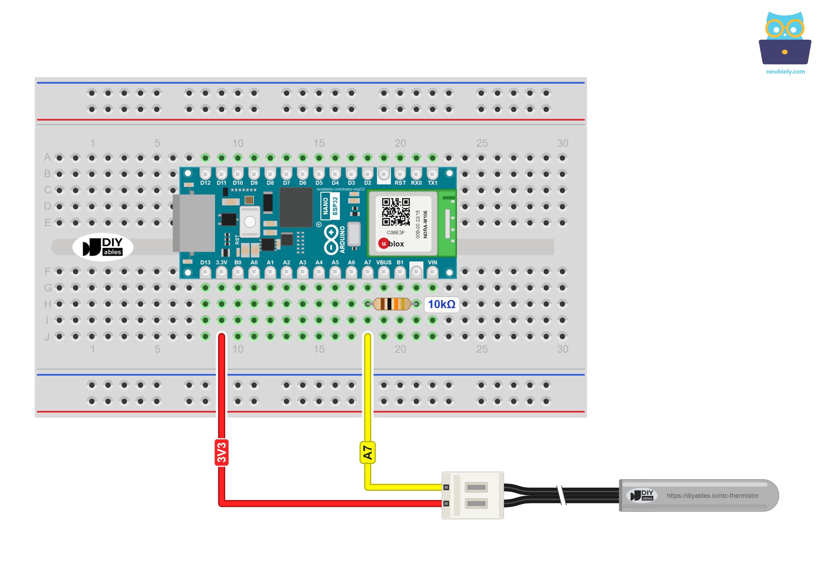
This image is created using Fritzing. Click to enlarge image
Without a breadboard, solder the 10K resistor between the A7 wire and the GND wire, like this:
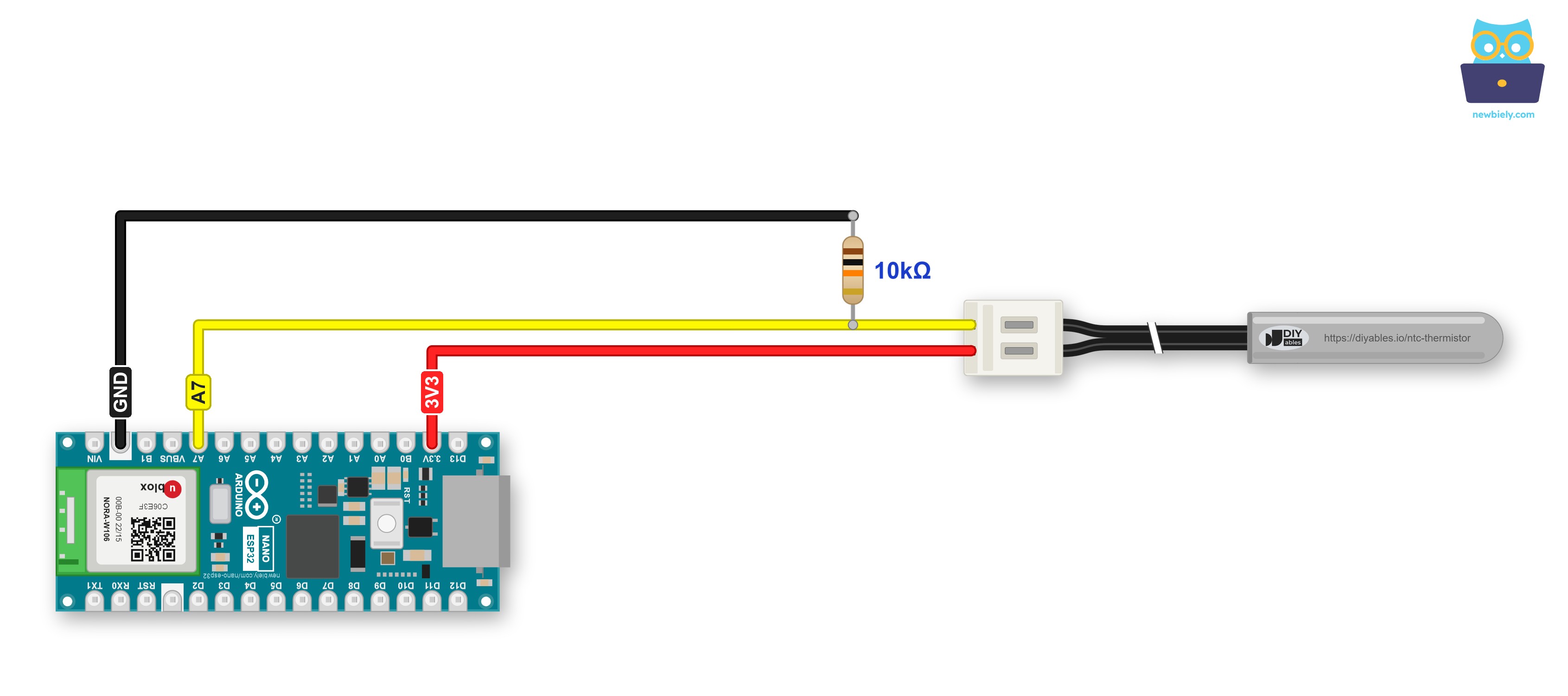
This image is created using Fritzing. Click to enlarge image
| Thermistor + 10K Resistor | Arduino Nano ESP32 Pin |
|---|---|
| Thermistor lead (either one) | 3V3 (not VBUS) |
| Thermistor lead (the other one) | A7 |
| 10K resistor, top leg | A7 |
| 10K resistor, bottom leg | GND |
A screw terminal keeps each wire tight, even when the board shakes. The Arduino Nano ESP32 fits a Screw Terminal Expansion Board for Arduino Nano, which turns every pin into a screw terminal. See the diagram below for the screw terminal version.
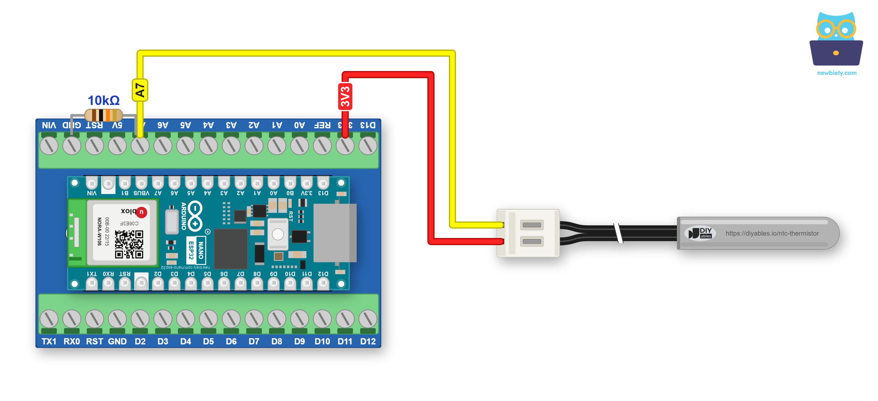
This image is created using Fritzing. Click to enlarge image
On the screw terminal board, the 10K resistor is screwed straight into the GND terminal and the A7 terminal, where it shares the A7 terminal with the probe's wire. So there is no GND wire at all.
※ NOTE THAT:
Water is fine for the steel tip, but not for the rest. Everything else (plug, jumper wires, resistor joint) must stay dry, so keep them above the water line, for example taped to the side of the pot or jar.
How To Program For NTC Thermistor Temperature Sensor
There is nothing to install. analogReadMilliVolts() comes with the Arduino core for the Nano ESP32, and log() is a standard C++ math function.
- Give the analog pin a name and store the probe numbers:
- Inside setup(), widen the ADC input range to about 3.1V:
- Ask for the voltage on A7 in millivolts. This function applies the factory calibration saved in the ESP32-S3 chip. The full sketch repeats it 20 times and uses the average:
- Get the thermistor's ohms from the divider rule:
- Put the ohms into the beta equation to get °C. Note that log() in C++ means ln, the natural logarithm, not log10:
Why millivolts, and not analogRead() divided by 4095? The ESP32-S3 ADC bends away from a straight line near both ends of its range, and with ADC_11db its upper limit ends near 3.1V instead of 3.3V. A plain ratio would get the resistance wrong, mostly when the probe is very cold or very hot. The calibrated millivolt reading avoids both problems.
Arduino Nano ESP32 Code - NTC Thermistor Temperature Sensor
The complete sketch writes one line to the Serial Monitor every second: the averaged A7 voltage, the thermistor's ohms, and the temperature in °C and °F. If A7 stays near 0V or near 3.3V, you get a short wiring hint in place of a temperature.
Detailed Instructions
Follow these instructions step by step:
- If this is the first time you use Arduino Nano ESP32, see how to setup environment for Arduino Nano ESP32 on Arduino IDE.
- Make the four connections from the wiring table. Before you go on, look again: one thermistor lead must sit on 3V3, not on VBUS.
- Plug a USB Type-C cable into the Nano ESP32 and into your PC.
- Launch the Arduino IDE on your computer.
- Select the appropriate Arduino Nano ESP32 board (e.g., Arduino Nano ESP32) and COM port.
- Paste the code above into a new sketch, then press Upload.
- Open the Serial Monitor and choose 9600 baud.
- Let a few lines scroll by with the probe on the desk. Next, lower the probe into a cup of tea that has been standing for some minutes.
Lines one to three were taken with the probe lying on the desk, at about 22.6°C. As soon as the tip touches the tea, look at the two middle columns: the millivolts go up while the ohms go down, from about 11kΩ to 2.2kΩ. That opposite movement is the "negative" in NTC. The temperature climbs over five or six lines, not in one step, because the heat has to pass through the steel before it reaches the thermistor. Trust the number once it stops changing.
Two messages can replace the temperature. "A7 is near 0V" means the plug has come off or the 3V3 wire is loose. "A7 is near 3.3V" means the 10K resistor has lost its GND connection, or the two probe wires touch.
※ NOTE THAT:
Do you have a kitchen thermometer? Put it and the probe side by side in the same glass of water and compare the two numbers. If the Nano ESP32 always shows a bit more or a bit less, add or subtract that difference to temp_c in the code.
Keep this probe at 105°C or below. Ovens, grills and kilns need a thermocouple, which is covered in Arduino Nano ESP32 - MAX6675 Thermocouple Module. If you would rather skip the resistor and the math, the DS18B20 probe gives a finished digital reading: see Arduino Nano ESP32 - Temperature Sensor.