
Arduino Nano ESP32 - Slide Switch
In this guide, we will learn how to use a mini slide switch with the Arduino Nano ESP32. Picture a small IoT gadget that should either join your home WiFi or open its own hotspot. That choice must not change by itself, and it must still be there after a power cut. A slide switch on the side of the case does this job: you set it once, and the Nano ESP32 reads it whenever it needs to. In detail, we will learn:
- Which of the three SS12D10 legs is COM, and how the handle decides which outer leg it joins.
- How to hook the switch up to the Nano ESP32 with three jumper wires: COM to D2, pin 1 to GND, pin 3 to 3V3.
- How to show the handle position on the Serial Monitor, one line per move, with a 50 ms debounce.
- How a two-wire version with INPUT_PULLUP works, and why LOW then stands for ON.
Hardware Preparation
Or you can buy the following kits:
| 1 | × | DIYables Sensor Kit (18 sensors/displays) |
Additionally, some of these links are for products from our own brand, DIYables .
Overview of Slide Switch SS12D10
Think of the SS12D10 as a tiny railway point. One track (the COM leg) comes in, and the handle decides which of two other tracks it leads to. The part is small enough to peek out of the side of a 3D-printed case, with a 5 mm handle and three legs in one row. Once you slide the handle, it does not spring back. It waits at that end until you move it again. That is called latching, and it is exactly what a push button does not do. The datasheet name for this kind of switch is SPDT (single pole, double throw), or 1P2T.
| SS12D10 Slide Switch | |
|---|---|
| Switch type | SPDT (1P2T), 2 positions |
| Number of legs | 3 |
| Leg pitch | 4.7 mm |
| Leg length | 6.9 mm |
| Handle | 5 mm long |
| Size of the body | about 12.8 x 6.7 x 18.2 mm |
| Mounting style | vertical, through-hole |
| Contact metal | silver-plated brass |
| Rated load | AC 125V 2A |
| Life span | more than 100,000 switching cycles |
| Temperature range | -25°C to 80°C |
About the AC 125V 2A rating: you will not get close to it here. Reading a pin with the Nano ESP32 needs only a tiny current through the contacts.
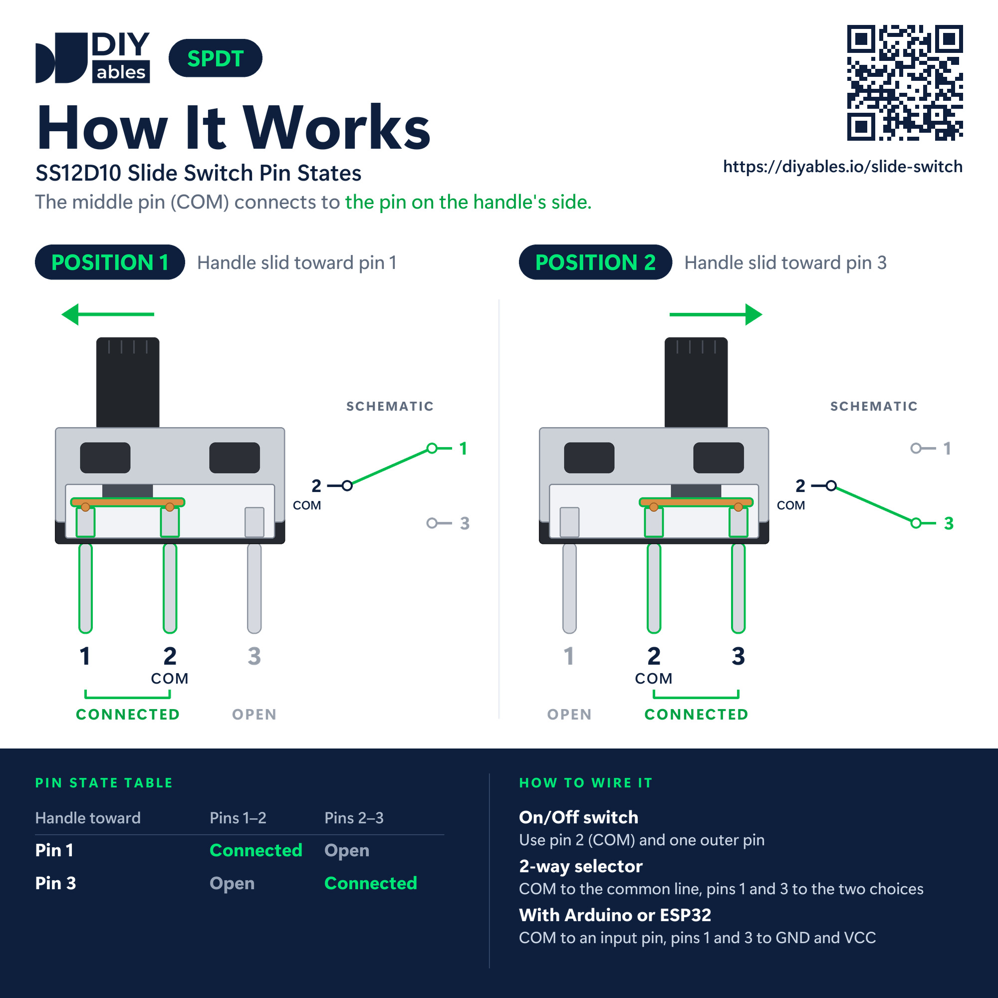
The switch has no markings, so count the legs. The center one is COM. The legs at the two ends of the row are pin 1 and pin 3:
- Pin 1 (one end of the row): connect to GND.
- Pin 2, COM (center): connect to D2 of the Nano ESP32. Another free digital pin also works, but the code uses D2.
- Pin 3 (other end of the row): connect to 3V3 of the Nano ESP32.
Under the handle sits a little metal bridge that travels with it. One end of the bridge rests on COM all the time. The other end lands on the outer leg that the handle points to:
- Handle near pin 1 → COM connects to pin 1. Pin 3 is unused.
- Handle near pin 3 → COM connects to pin 3. Pin 1 is unused.
Put GND on pin 1 and 3.3V on pin 3, and COM becomes a simple 0V-or-3.3V signal for D2. We call the 3.3V side (HIGH) "ON" and the GND side (LOW) "OFF". One small catch: metal contacts chatter for a few milliseconds after each move, so the sketch reads twice before it believes a change.
Wiring Diagram
For the main wiring, plug three jumper wires straight onto the switch legs and the Nano ESP32 headers. No resistor is used. D2 sees GND through pin 1 or 3.3V through pin 3, so it has a clear level in both positions, and plain INPUT mode is enough.
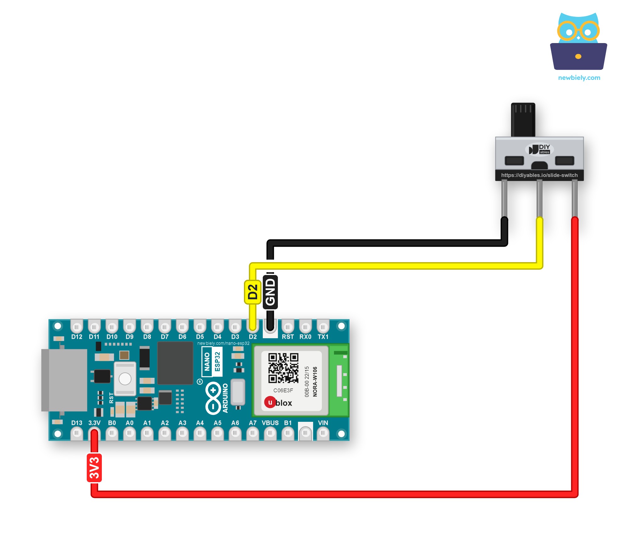
This image is created using Fritzing. Click to enlarge image
| Slide Switch Pin | Arduino Nano ESP32 Pin |
|---|---|
| Pin 1 | GND |
| Pin 2 (COM) | D2 |
| Pin 3 | 3V3 (not VBUS) |
If the project will run for a long time, or sit inside a box, it is better to fix the wires with screws. The Arduino Nano ESP32 fits a Screw Terminal Expansion Board for Arduino Nano, which turns every pin into a screw terminal. See the diagram below for the screw terminal version.
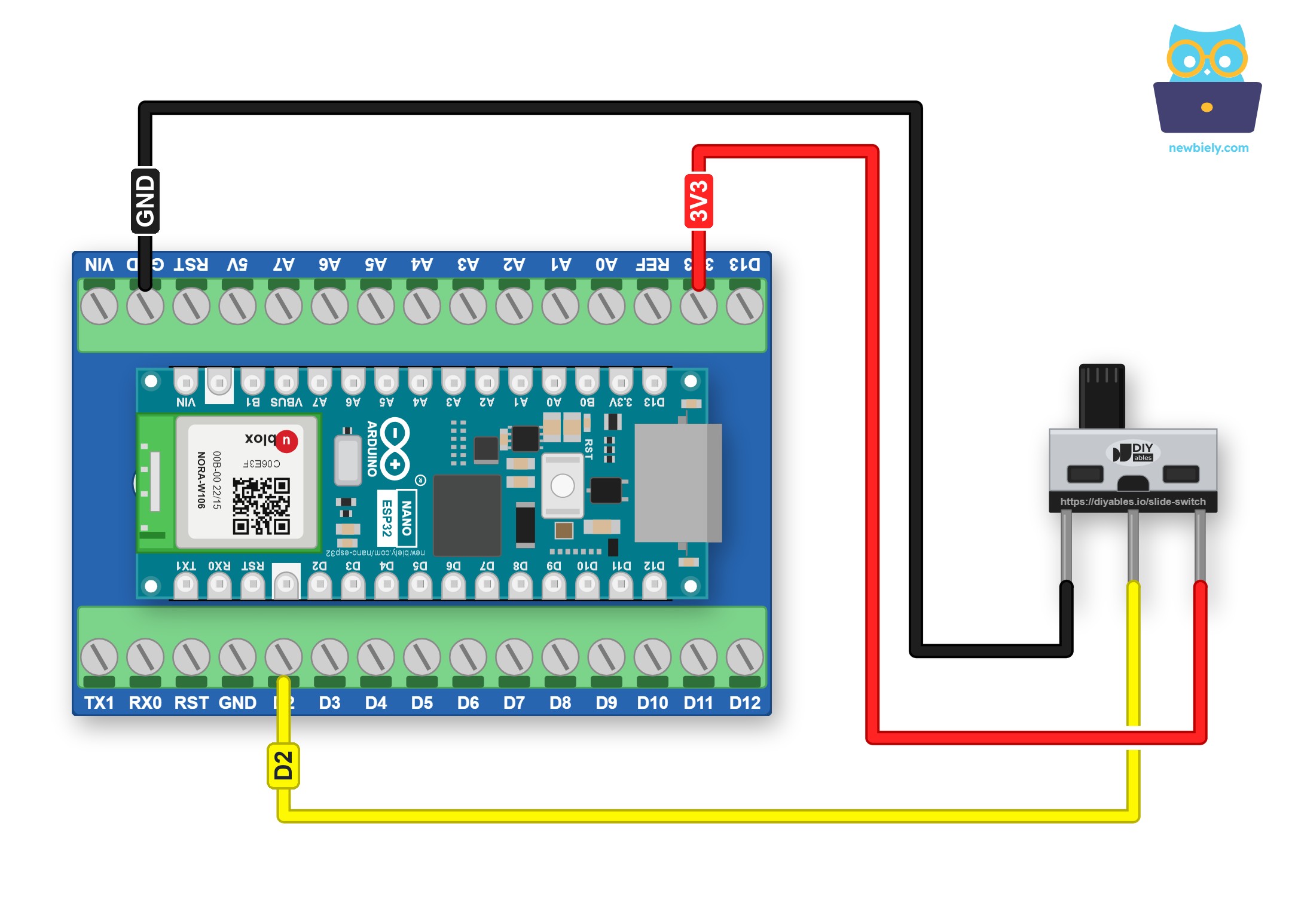
This image is created using Fritzing. Click to enlarge image
※ NOTE THAT:
Before you power up, check these two points:
- The pin 3 wire belongs on 3V3. Do not move it to VBUS or VIN. With the handle near pin 3, COM hands that voltage directly to D2, and the GPIO pins of the ESP32-S3 chip accept 3.3V only. A 5V level can kill the pin.
- Leave D2 in input mode. If a sketch ever makes it an OUTPUT, the switch would short that output to 3V3 or GND, and the pin can be damaged.
How To Program For Slide Switch
Reading the switch uses only built-in functions:
- Pick a name for D2, the pin that listens to COM:
- In setup(), make D2 a normal input. The internal pull-up stays off, since pin 1 and pin 3 already give both levels:
- Get the current level. You see HIGH when the handle is near pin 3 (ON) and LOW when it is near pin 1 (OFF):
- Keep the previous level in a variable. If a new reading does not match it, pause 50 ms, read once more, and print the state only if the new level is still there.
Arduino Nano ESP32 Code - Slide Switch
The full sketch starts with one line that shows where the handle is. From then on, a new line appears only when you slide the handle to the other end.
Detailed Instructions
Follow these instructions step by step:
- If this is the first time you use Arduino Nano ESP32, see how to setup environment for Arduino Nano ESP32 on Arduino IDE.
- Make the three connections from the table above. Check twice that pin 3 is on 3V3.
- Plug the Nano ESP32 into a USB port of your PC with the Type-C cable.
- Launch the Arduino IDE on your computer.
- Select the appropriate Arduino Nano ESP32 board (e.g., Arduino Nano ESP32) and COM port.
- Copy the code above into a new sketch, then click the Upload button.
- Click the Serial Monitor icon and pick 9600 baud.
- Push the handle back and forth about four times, pausing at each end for a second.
Four moves, four lines: the contact chatter never shows up as extra lines. Right after the upload, the Nano ESP32 resets and its USB port reconnects. If the "at start" line did not appear, the Serial Monitor simply missed it. Slide the handle and the next lines will show.
Arduino Nano ESP32 Code - Two-Wire Slide Switch with INPUT_PULLUP
Short on jumper wires, or is the 3V3 pin already busy with a sensor? The ESP32-S3 on this board has a pull-up resistor built into each GPIO, and INPUT_PULLUP switches it on. With it, the 3V3 wire is no longer needed. Just remove the pin 3 wire: COM stays on D2, pin 1 stays on GND, and pin 3 is left free.
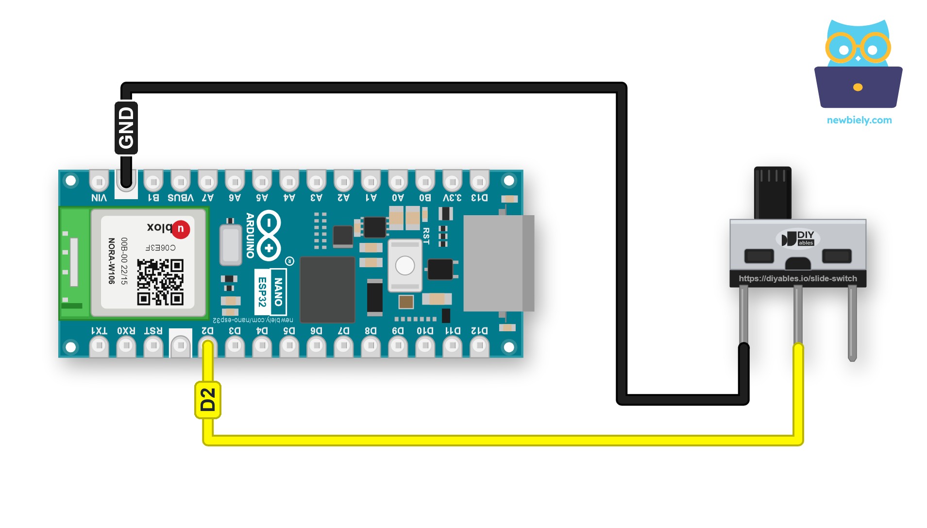
This image is created using Fritzing. Click to enlarge image
| Slide Switch Pin | Arduino Nano ESP32 Pin |
|---|---|
| Pin 1 | GND |
| Pin 2 (COM) | D2 |
| Pin 3 | not connected |
Now the meaning of HIGH and LOW is reversed:
- Handle near pin 1: the bridge ties COM, and so D2, to GND. D2 reads LOW, and the sketch calls that ON.
- Handle near pin 3: COM touches only the free pin 3, so nothing drives D2. The pull-up lifts it to HIGH, and the sketch calls that OFF.
Detailed Instructions
- Pull off the wire between pin 3 and 3V3. Keep the other two wires.
- Upload the code above to the Arduino Nano ESP32.
- Watch the Serial Monitor (still 9600 baud) while you flip the handle three times.
Which version should you pick? The 3-wire one reads the natural way (HIGH = ON). The 2-wire one is tidier inside a small case. If you need a panel-mount rocker that you flip with a finger, go to Arduino Nano ESP32 - Switch. Several tiny switches in one chip-shaped block? Try Arduino Nano ESP32 - DIP Switch. And for a key that does not latch, read Arduino Nano ESP32 - Button Module.