
ESP32 S3 - LED Matrix via Web
LED matrix displays paired with a Wi-Fi web interface create a powerful combination for remote signage and real-time message boards. In this tutorial, you will learn how to program the ESP32 S3 to act as a WebSocket-enabled web server that accepts text messages from any browser and immediately scrolls them across a connected LED matrix display.
What you'll build:
- An ESP32 S3 web server that serves a browser-based control page over Wi-Fi
- A WebSocket connection that lets users type and send messages from a browser in real time
- An LED matrix display that shows the received message as soon as the ESP32 S3 receives it
- A complete Arduino sketch with a companion HTML/CSS/JavaScript file for the web interface
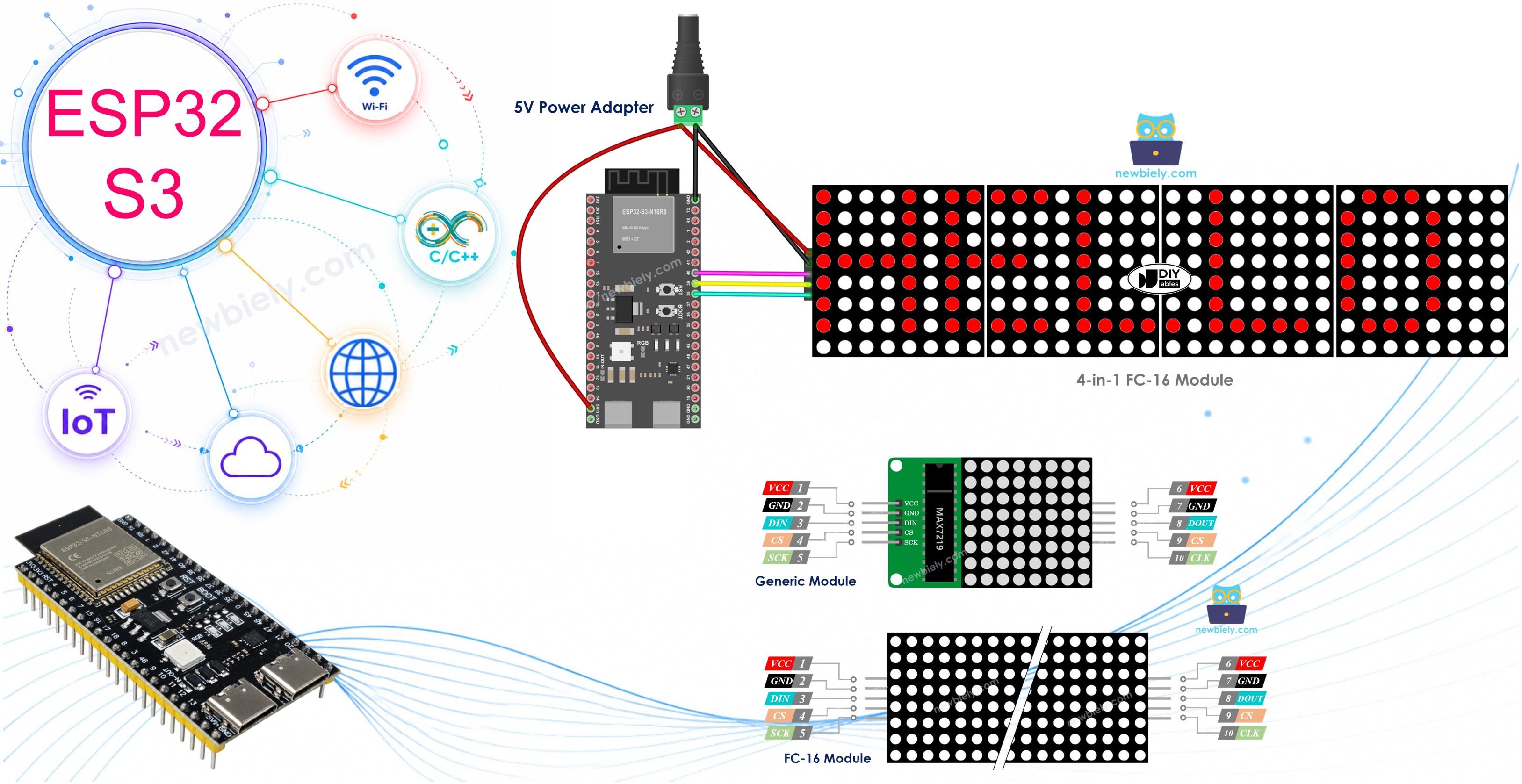
Hardware Preparation
Or you can buy the following kits:
| 1 | × | DIYables ESP32 S3 Starter Kit (ESP32 S3 included) | |
| 1 | × | DIYables Sensor Kit (18 sensors/displays) |
Additionally, some of these links are for products from our own brand, DIYables .
Overview of LED Matrix and Web Server
The ESP32 S3 can host a complete web interface and WebSocket server simultaneously, using its built-in Wi-Fi to receive messages from any browser on the same network. While a plain HTTP POST could be used to send text to the board, WebSocket makes the communication feel instant and responsive — the browser stays connected and the ESP32 S3 receives each message with minimal latency, without the overhead of opening a new HTTP connection each time.
Key Concepts
- WebSocket provides a persistent, bidirectional connection between the browser and the ESP32 S3
- The ESP32 S3 acts as both a web server (serving the HTML page) and a WebSocket server (receiving messages)
- Received messages are passed directly to the LED matrix for display
To learn more about the individual components involved, see these companion tutorials:
- ESP32 S3 - LED Matrix tutorial
- ESP32 S3 - Web Server tutorial
- ESP32 S3 - WebSocket tutorial
Wiring Diagram
Connect the LED matrix input pins to the ESP32 S3 using the SPI interface as shown in the diagram below, making sure the power supply can handle the current draw of the display.
Safety Notes
The FC-16 LED matrix can draw up to 1A at maximum brightness when all LEDs are lit. Do not rely solely on the ESP32 S3's onboard 5V pin to power the display — use an external 5V power supply and let both the ESP32 S3 and LED matrix share the same supply's ground.
Wiring connections (ESP32 S3 → LED Matrix input pins):
- 5V : VCC
- GND : GND
- GPIO38 : CLK (clock)
- GPIO40 : DIN (data in)
- GPIO39 : CS (chip select)
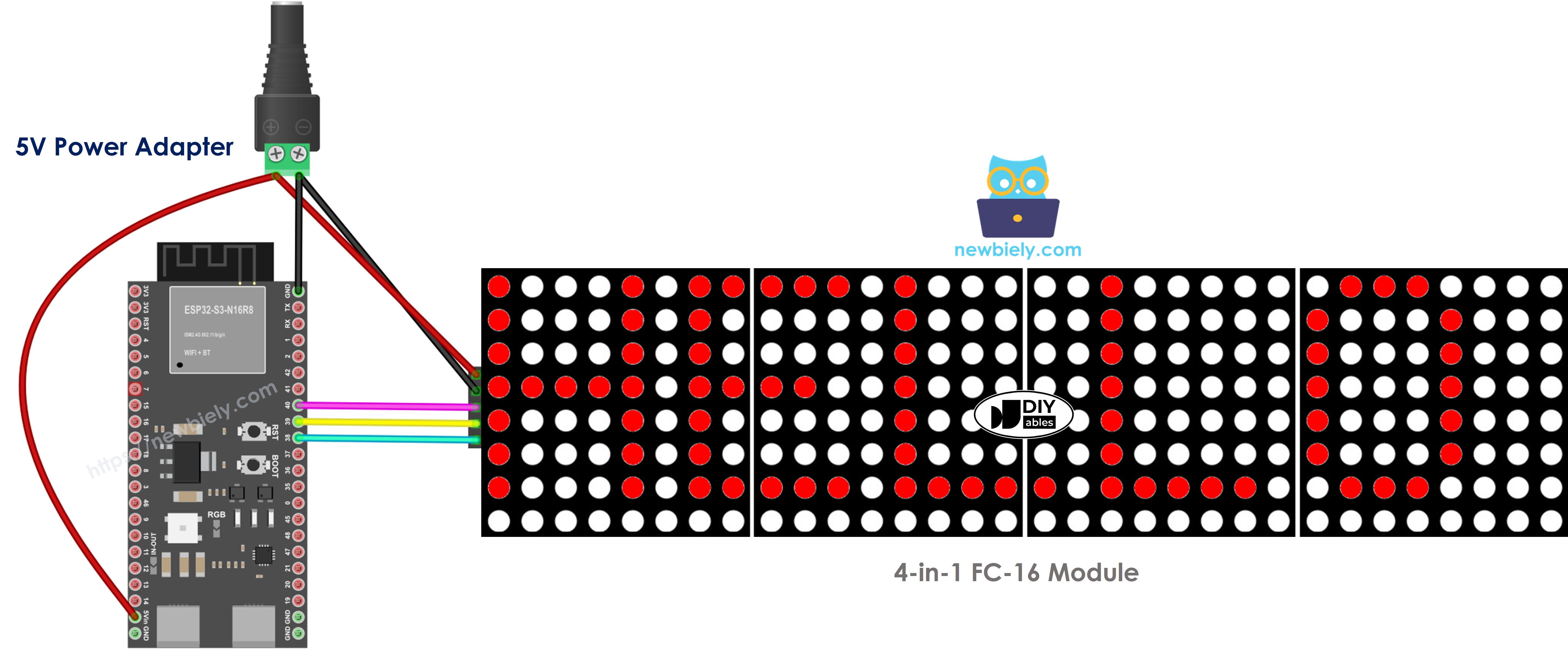
This image is created using Fritzing. Click to enlarge image
ESP32 S3 Code
The sketch is split across two files to keep the web interface separate from the board logic. The main .ino file sets up the Wi-Fi connection, instantiates the web server and WebSocket server, and drives the LED matrix. The companion index.h file holds the HTML, CSS, and JavaScript for the browser control page. The following code shows both files — upload them together from Arduino IDE.
Detailed Instructions
- New to ESP32 S3? Complete our Getting Started with ESP32 S3 guide first.
- Do the wiring as shown in the diagram above.
- Connect the ESP32 S3 board to your PC via a USB Type-C cable.
- Open Arduino IDE on your PC.
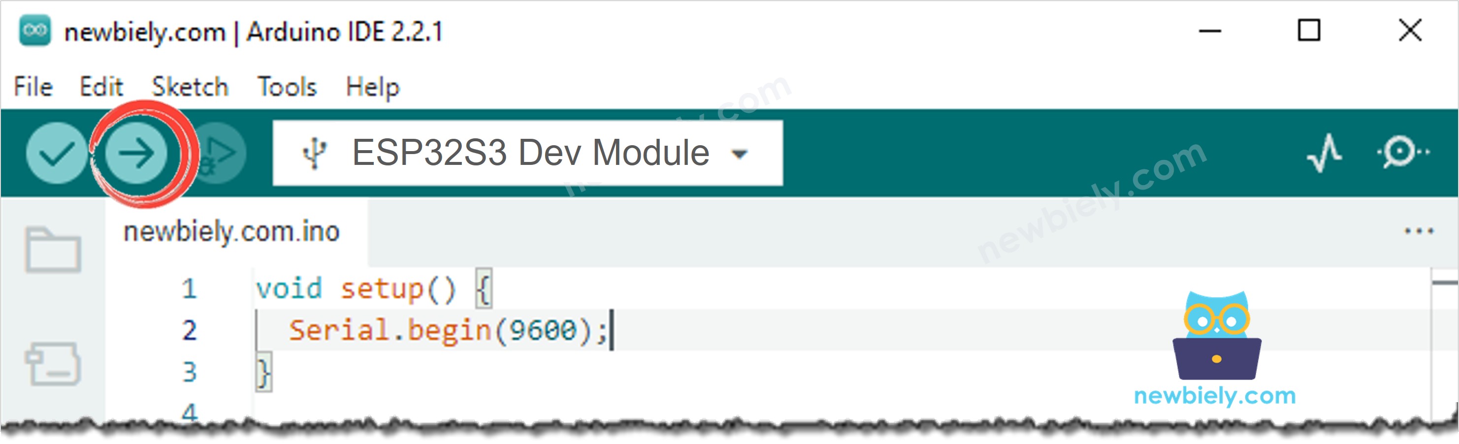
- Select the right ESP32 S3 board (e.g. ESP32S3 Dev Module) and COM port.
- Open the Library Manager by clicking on the Library Manager icon on the left navigation bar of Arduino IDE.
- Search "DIYables ESP32 WebServer", then find the Web Server library created by DIYables.
- Click Install button to install the Web Server library.
- Search for DIYables ESP32 WebServer created by DIYables.io and click the Install button.
- Search "MD_Parola", then find the MD_Parola library.
- Click Install button.
- Search for MD_Parola created by majicDesigns and click the Install button.
- You will be asked to install the "MD_MAX72XX" library.
- Click Install All button to install the dependency.
- On Arduino IDE, create a new sketch and give it a name, for example, newbiely.com.ino.
- Copy the above code and open it with Arduino IDE.
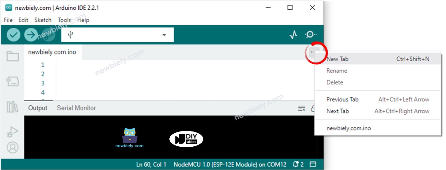
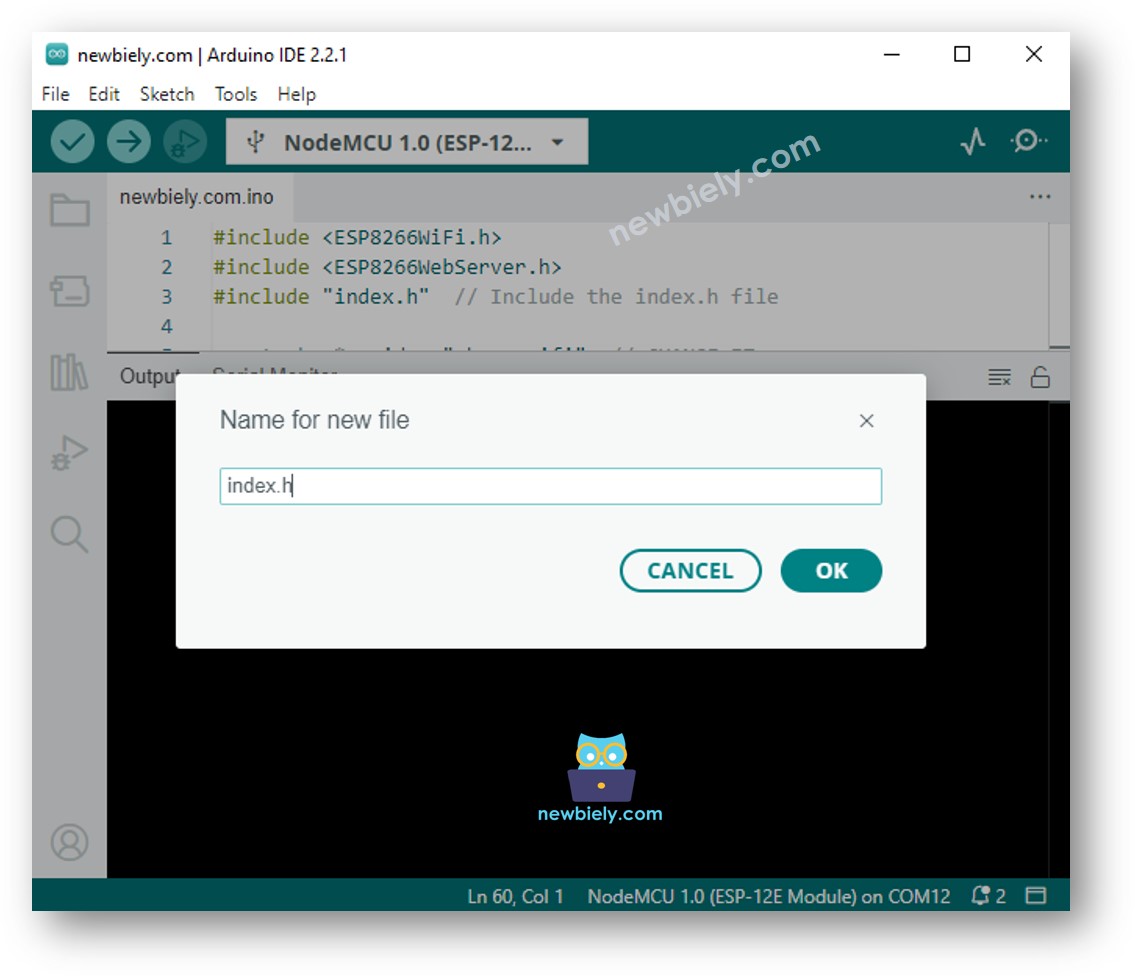
- Create the index.h file in Arduino IDE by:
- Either click on the button just below the serial monitor icon and choose New Tab, or use Ctrl+Shift+N keys.
- Give the file's name index.h and click OK button.
- Copy the below code and paste it into index.h.
- Now you have the code in two files: newbiely.com.ino and index.h.
- Update YOUR_WIFI_SSID and YOUR_WIFI_PASSWORD in the sketch with your network credentials.
- Click Upload button on Arduino IDE to upload code to ESP32 S3.
- Open the Serial Monitor and check the output.
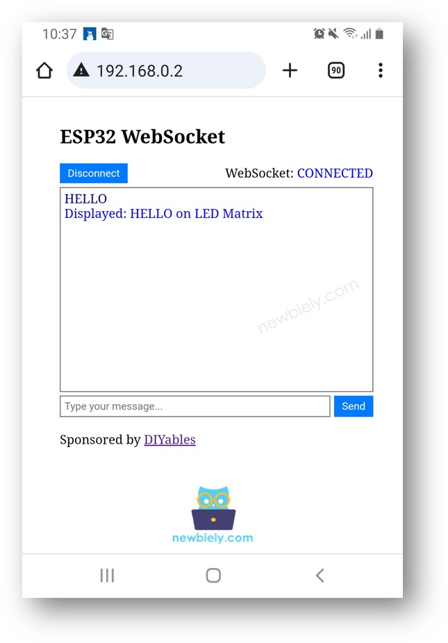
- Note the IP address shown in the Serial Monitor, then enter it in the address bar of a browser on your smartphone or PC.
- Click the CONNECT button to establish a WebSocket connection to the ESP32 S3.
- Type a message and send it to the ESP32 S3 — you will see it scroll across the LED matrix.
- If you modify the HTML content in the index.h and do not touch anything in the newbiely.com.ino file, Arduino IDE may not update the HTML content when you compile and upload.
- To force Arduino IDE to update the HTML content in this case, make a small change in the newbiely.com.ino file (for example, add an empty line or a comment).
※ NOTE THAT:
Line-by-line Code Explanation
The above ESP32 S3 code contains line-by-line explanation. Please read the comments in the code!
Serial Monitor Output
Open the Serial Monitor at 115200 baud to observe connection and messaging events from the ESP32 S3. The following readings show typical output during startup and when a web client sends a message:
- [2026-06-16 09:00:01] Connecting to WiFi...
- [2026-06-16 09:00:04] Connected to WiFi. IP address: 192.168.0.2
- [2026-06-16 09:00:10] WebSocket client connected
- [2026-06-16 09:00:15] Message received: "Hello World" — displaying on LED matrix
Applications
Web-controlled LED matrix displays are well-suited to scenarios where messages need to be updated remotely without physical access to the hardware. Here are some common applications:
- Office Announcement Board: Post meeting reminders, visitor notifications, or company announcements from any device on the office Wi-Fi network.
- Retail Promotion Display: Update promotional messages or pricing information on a shop-floor LED sign in real time without touching the hardware.
- Event Countdown Sign: Send time-sensitive messages such as session start times or queue status updates from an event management tablet.
- IoT Status Indicator: Display the current state of a connected system — such as server health or sensor alerts — by pushing status text from a backend service.
- Classroom or Lab Display: Allow an instructor to broadcast instructions or reminders to a classroom LED sign from a laptop without leaving the front of the room.
Video Tutorial
Watch the step-by-step video walkthrough for this ESP32 S3 project below.
Challenges
These challenges will help you extend the web-controlled LED matrix project and deepen your understanding of WebSocket communication and display control on the ESP32 S3.
- Beginner: Change the scroll speed of the LED matrix by adding a slider to the web interface that lets the user adjust the scrolling rate and sends the new speed value to the ESP32 S3 via WebSocket.
- Intermediate: Add a brightness control to the web interface that adjusts the setIntensity() value on the ESP32 S3 in real time, allowing users to dim the display remotely.
- Advanced: Extend the system to support multiple ESP32 S3 boards connected to different LED matrix displays, broadcasting the same message to all boards simultaneously from a single web interface.