
ESP32 S3 - Potentiometer Servo Motor
This tutorial shows you how to use the ESP32 S3 with a potentiometer to control the angle of a servo motor in real time. By reading the potentiometer's analog value through the ESP32 S3's ADC and mapping it to a servo angle, you create a direct, intuitive link between a physical dial and precise mechanical rotation.
What you'll build:
- A circuit connecting a potentiometer and a servo motor to the ESP32 S3
- A sketch that reads the potentiometer's analog value (0–4095) on the ESP32 S3
- Logic that maps the analog reading to a servo angle between 0° and 180°
- Serial Monitor output that displays live analog values and the resulting servo angle
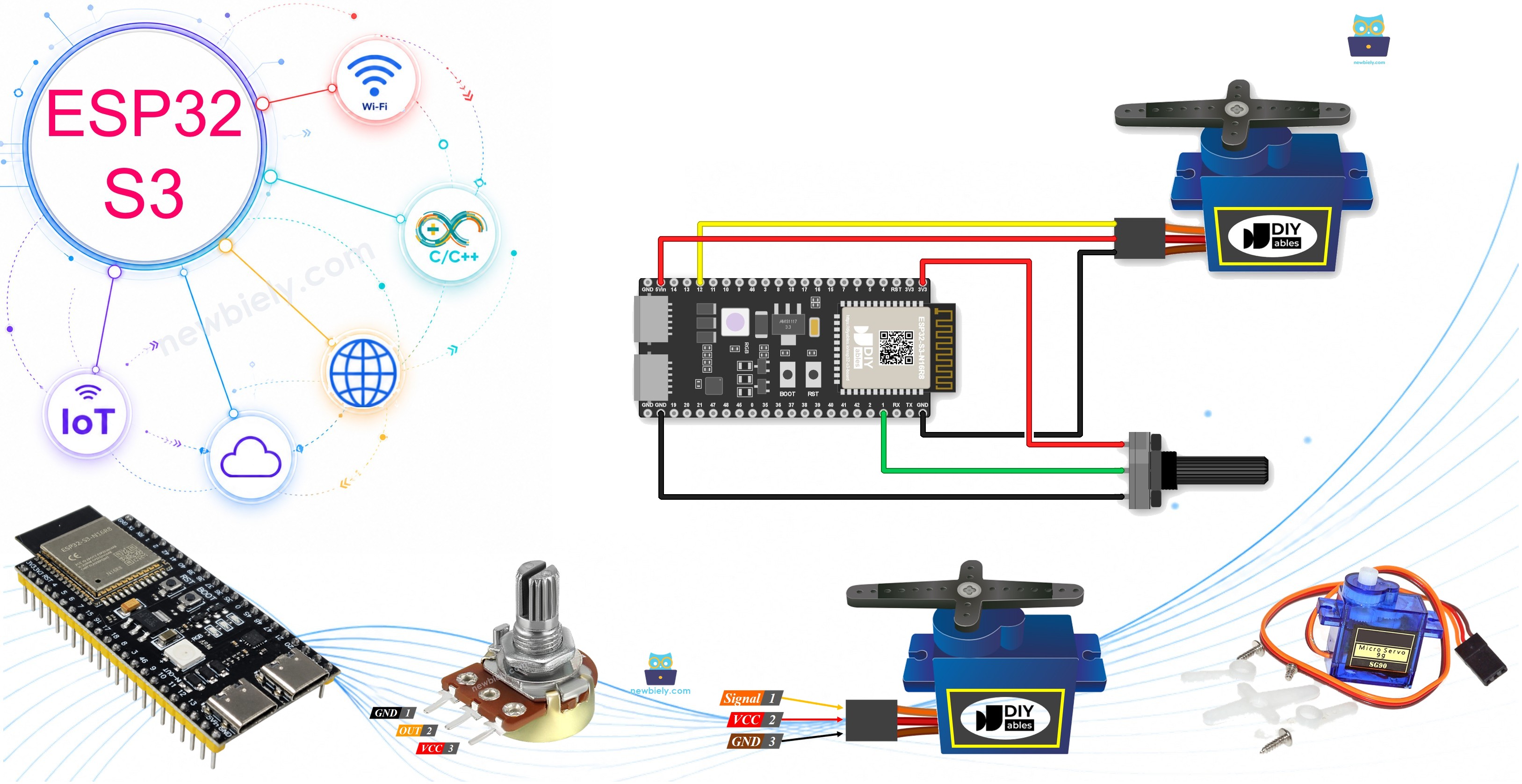
Hardware Preparation
Or you can buy the following kits:
| 1 | × | DIYables ESP32 S3 Starter Kit (ESP32 S3 included) | |
| 1 | × | DIYables Sensor Kit (18 sensors/displays) |
Additionally, some of these links are for products from our own brand, DIYables .
Buy Note: For controlling multiple servo motors, use the PCA9685 16 Channel PWM Servo Driver Module to save MCU pins and simplify wiring.
Overview of Servo Motor and Potentiometer
The servo motor and potentiometer are a classic combination for analog-driven motion control with the ESP32 S3. The potentiometer acts as a variable voltage divider that the ESP32 S3 reads through its 12-bit ADC, producing a value from 0 to 4095, while the servo motor converts the mapped angle command into precise physical rotation. Together they form a closed-loop feel in which turning the knob produces immediate, proportional mechanical movement.
Key Specifications
We have dedicated tutorials covering each component in depth. Each tutorial contains detailed information and step-by-step instructions about hardware pinout, working principle, wiring connection to the ESP32 S3, and Arduino code. Learn more about them at the following links:
Wiring Diagram
Connect the potentiometer and servo motor to your ESP32 S3 by following the diagram below. Double-check all connections before applying power, paying particular attention to the servo's power and signal wires.
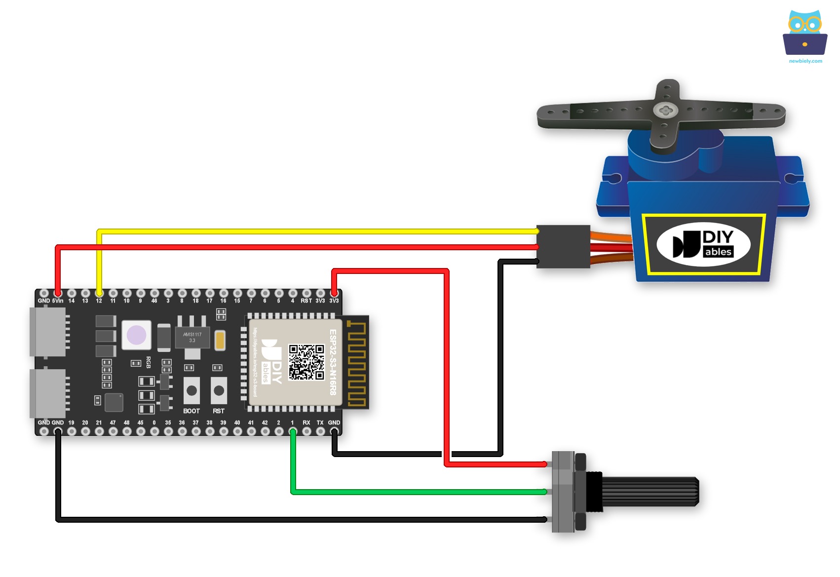
This image is created using Fritzing. Click to enlarge image
Do you want the wiring to stay in place? A Screw Terminal Block for ESP32 S3 solves this. Plug the ESP32 S3 into it and screw the wires in. The pins do not change. Just connect each wire to the matching screw terminal:
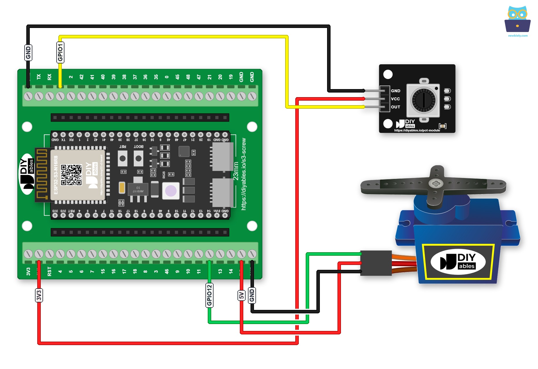
This image is created using Fritzing. Click to enlarge image
Or plug the ESP32 S3 into a GPIO Breakout Board for ESP32 S3. The same wiring then looks like this:
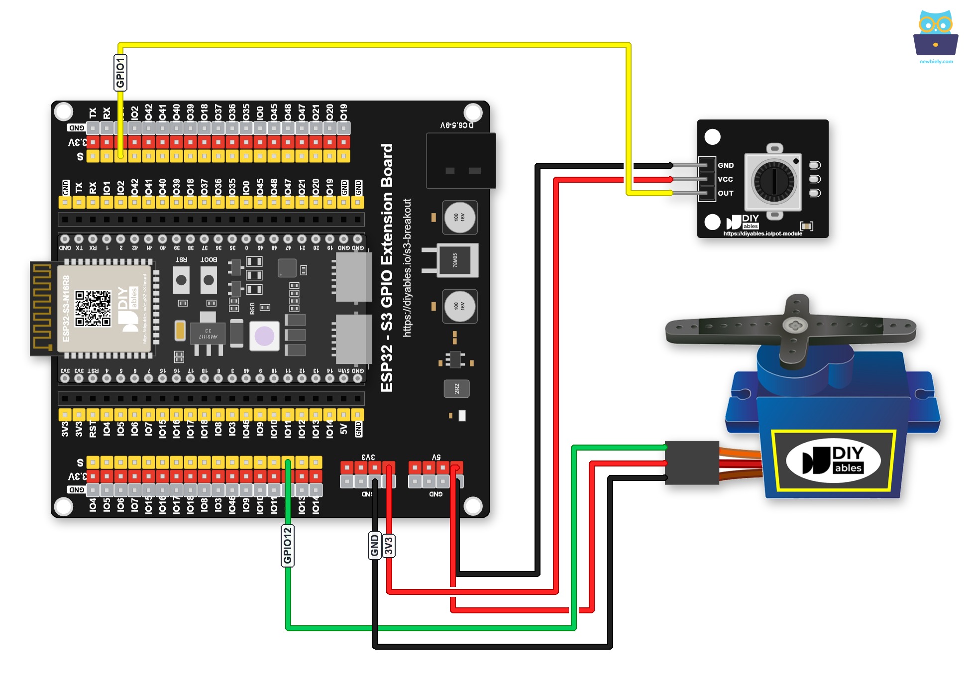
This image is created using Fritzing. Click to enlarge image
Safety Notes
Standard hobby servo motors can briefly draw several hundred milliamps during movement, which may exceed what the ESP32 S3's USB supply can safely provide under continuous load. For bench testing, the USB port is usually sufficient; for any load-bearing or extended-run application, power the servo from a dedicated 5 V external supply and share only the GND rail with the ESP32 S3.
| Component | Pin | ESP32 S3 Pin |
|---|---|---|
| Potentiometer | Left pin | 3.3V |
| Potentiometer | Middle pin (wiper) | GPIO1 |
| Potentiometer | Right pin | GND |
| Servo Motor | GND (Brown/Black) | GND |
| Servo Motor | VCC (Red) | 5V |
| Servo Motor | Signal (Yellow/Orange) | GPIO12 |
ESP32 S3 Code
The following code reads the potentiometer's analog value on the ESP32 S3, maps it to a servo angle between 0° and 180°, and then commands the servo to move to that angle. The ESP32Servo library handles the PWM signal generation so the servo receives a precise pulse-width command on every loop iteration.
Detailed Instructions
- New to ESP32 S3? Complete our Getting Started with ESP32 S3 guide first.
- Wire the potentiometer and servo motor to the ESP32 S3 following the wiring diagram shown above.
- Connect the ESP32 S3 board to your PC using a USB Type-C cable.
- Open Arduino IDE on your PC.
- Select the correct ESP32 S3 board and COM port from the Tools menu.
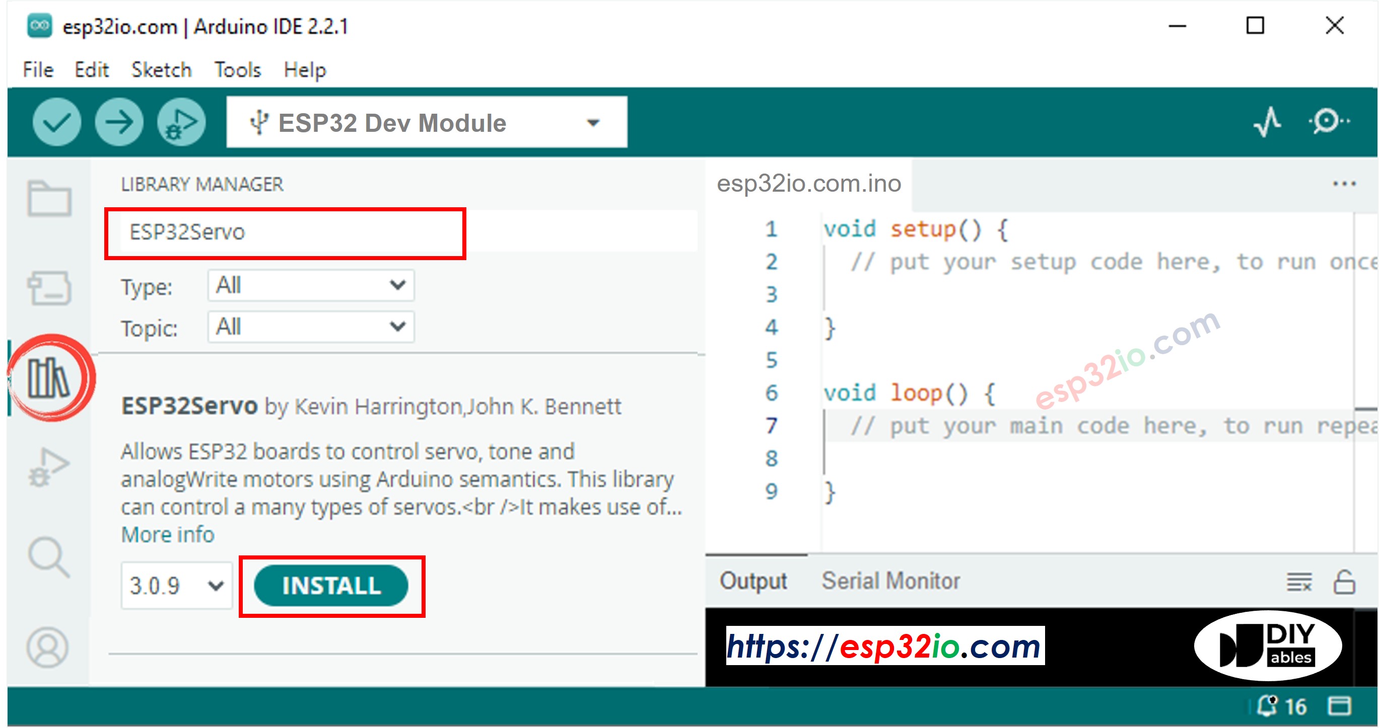
- Click the Libraries icon on the left bar of the Arduino IDE.
- Type ESP32Servo in the search box, then find the servo library by Kevin Harrington, John K. Bennett.
- Click Install to install the servo motor library for ESP32.
- Copy the above code and paste it into Arduino IDE.
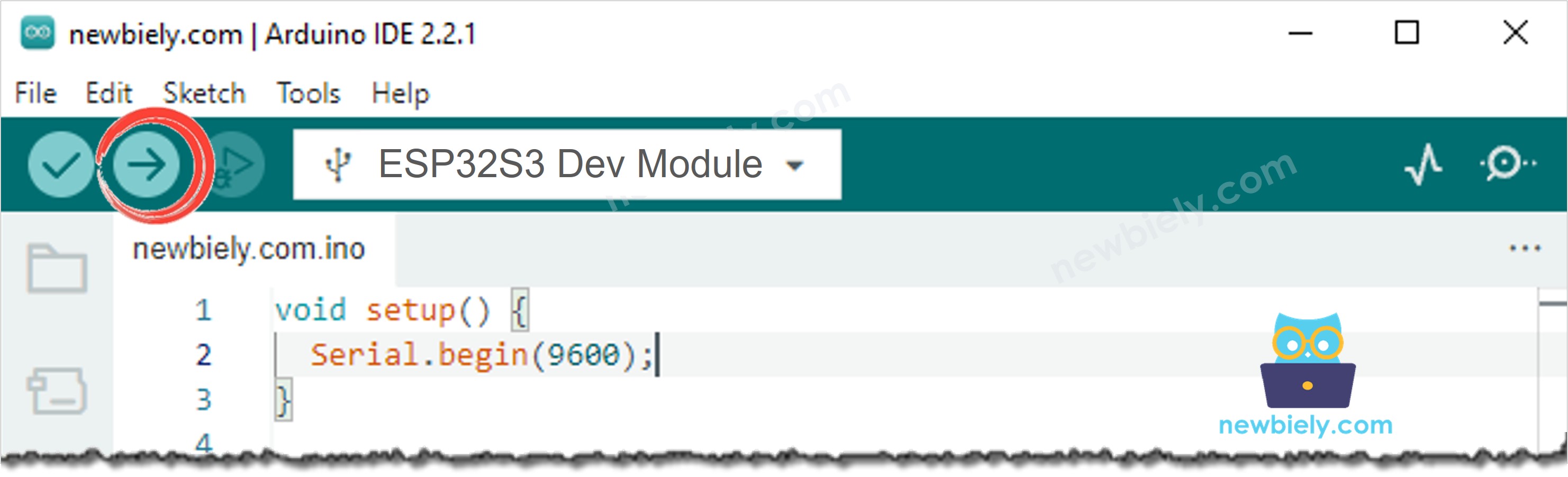
- Click the Upload button to compile and upload the code to the ESP32 S3.
- Open the Serial Monitor at 9600 baud.
- Rotate the potentiometer knob slowly from one end to the other.
- Observe the servo motor rotating in proportion to the knob position.
- View the live analog readings and servo angles in the Serial Monitor.
- Pro Tip: If you notice the servo jittering at rest, add a small deadband check in the code so the servo only updates when the analog reading changes by more than a fixed threshold (e.g., ±10 counts) — this eliminates noise-induced micro-movements.
Line-by-line Code Explanation
The above ESP32 S3 code contains line-by-line explanation. Please read the comments in the code!
Serial Monitor Output
The following Serial Monitor output shows the ESP32 S3 responding to potentiometer rotation in real time. Each line displays the raw analog value read from the ADC alongside the calculated servo angle so you can verify the mapping as you turn the dial.
※ NOTE THAT:
This tutorial uses the analogRead() function to read values from an ADC (Analog-to-Digital Converter) connected to a potentiometer. The ESP32 S3 ADC is suitable for projects that do NOT need high accuracy. However, for projects that need precise measurements, please note:
- The ESP32 S3 ADC is not perfectly accurate and might need calibration for correct results. Each ESP32 S3 board can be a bit different, so you need to calibrate the ADC for each individual board.
- Calibration can be difficult, especially for beginners, and might not always give the exact results you want.
For projects that need high precision, consider using an external ADC (e.g ADS1115) with the ESP32 S3 or using an Arduino, which has a more reliable ADC. If you still want to calibrate the ESP32 S3 ADC, refer to ESP32 ADC Calibration Driver
Application and Project Ideas
Once you master potentiometer-driven servo control on the ESP32 S3, you can apply this analog-to-angle mapping pattern to a wide range of practical motion-control and robotics projects.
- Robotic arm joint: Use a potentiometer knob on a control panel to set the angle of a single robotic arm joint in a multi-servo build.
- Manual camera pan-tilt: Mount a servo on a camera rig and dial in the exact pan angle using a potentiometer for precise framing.
- Adjustable valve controller: Attach a servo to a flow valve and use a potentiometer to set the desired flow rate as a percentage of full open.
- Interactive display pointer: Drive a servo-mounted arrow or pointer on a dashboard to a user-selected position using a dial on the ESP32 S3.
- Steering servo calibration: Use the potentiometer to manually set neutral and end-stop positions on a remote-controlled vehicle's steering servo.
- Prototype door angle setter: Control the opening angle of a servo-driven hatch or door panel with a physical knob for repeatable testing.
Video Tutorial
Watch the step-by-step video walkthrough for this ESP32 S3 project below.
Challenge Yourself
Now that you can control a servo motor with a potentiometer on the ESP32 S3, try these progressively challenging extensions to deepen your understanding of analog input and servo control.
- Beginner: Limit the servo range to 0°–90° by adjusting the map() arguments and verify the servo stops at 90° even when the potentiometer is at its maximum.
- Beginner: Add a Serial Monitor print statement that shows the raw analog value, the calculated voltage (in volts), and the servo angle on the same line for each reading.
- Intermediate: Implement a deadband so the servo only updates when the analog reading changes by more than 20 counts, eliminating jitter at stable potentiometer positions.
- Intermediate: Display the current potentiometer value and servo angle on an OLED or LCD screen so you can monitor the system without the Serial Monitor.
- Advanced: Add a second potentiometer to control a second servo motor on a separate GPIO pin, building the foundation of a two-axis pan-tilt camera mount.
- Advanced: Build a web interface served by the ESP32 S3 that displays the live servo angle on a gauge graphic and lets you set a software angle limit remotely via WiFi.