
ESP32 S3 - DHT11 - Relay
The DHT11 temperature sensor and a relay module give the ESP32 S3 everything it needs to build a simple automatic thermal switch that turns connected devices on or off based on real-world temperature readings. This tutorial guides you through wiring the sensor and relay to the ESP32 S3, writing the Arduino sketch that monitors temperature, and testing the system by applying heat to the sensor and watching the relay respond.
What you'll build:
- A circuit connecting a DHT11 temperature and humidity sensor and a relay module to the ESP32 S3
- A sketch that reads temperature from the DHT11 and switches the relay on or off based on configurable upper and lower thresholds
- An automatic thermal control system that activates a load (such as a 12V fan) when the environment gets too warm and deactivates it when it cools down
- A foundation you can extend into smart cooling systems, greenhouse controllers, or home automation projects
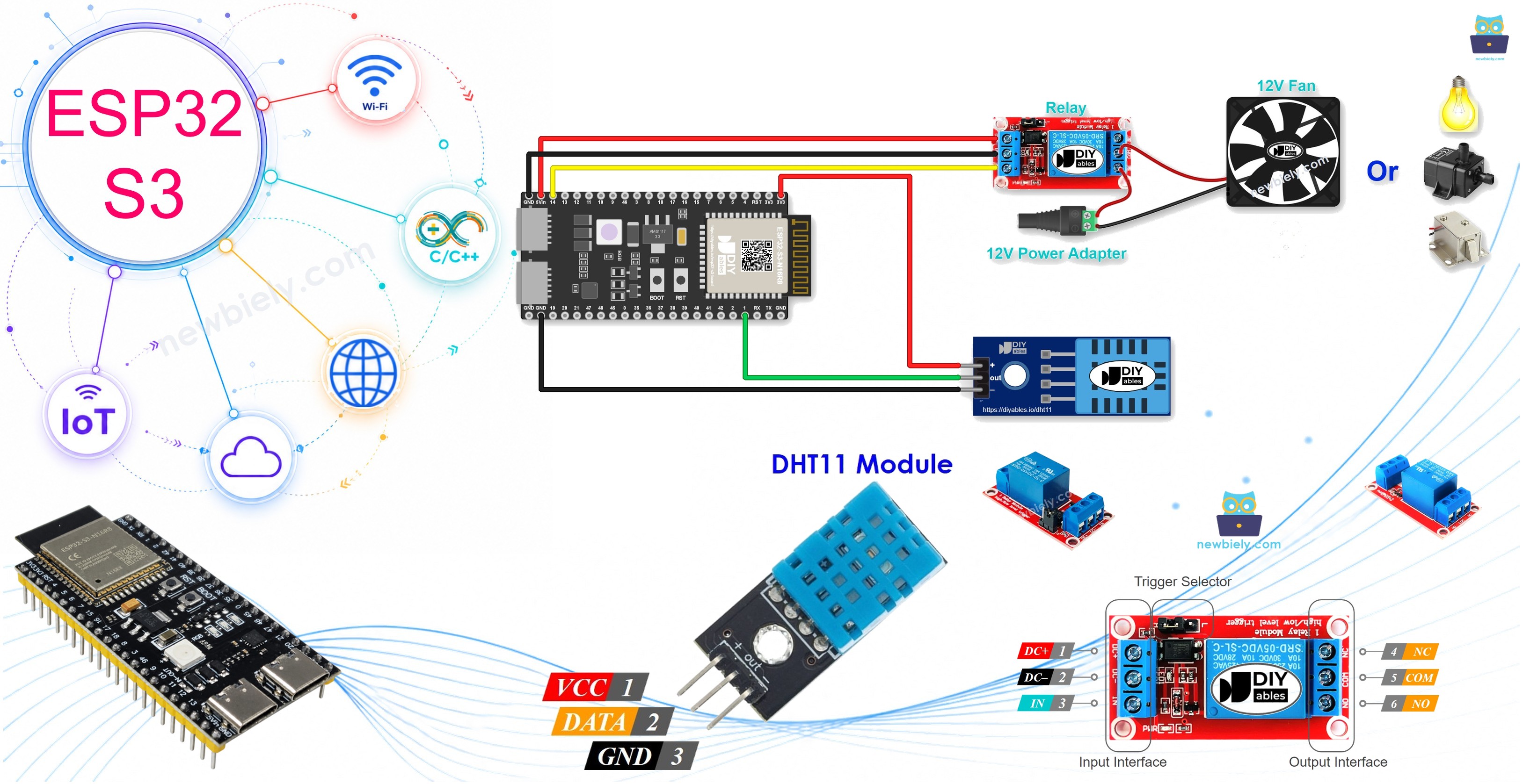
Hardware Preparation
Or you can buy the following kits:
| 1 | × | DIYables ESP32 S3 Starter Kit (ESP32 S3 included) | |
| 1 | × | DIYables Sensor Kit (18 sensors/displays) |
Additionally, some of these links are for products from our own brand, DIYables .
Overview of DHT11 Sensor and Relay
The DHT11 sensor uses a single-wire digital protocol to deliver calibrated temperature readings from 0 to 50 °C and relative humidity readings from 20 to 90 % RH, making it an accessible and affordable choice for indoor thermal monitoring projects. A relay module acts as an electronically controlled switch that allows the ESP32 S3 to safely toggle higher-voltage or higher-current loads — such as a 12V fan, a heater, or a pump — using only a low-current GPIO signal. Together, these two components turn the ESP32 S3 into an automatic thermal controller that responds to real environmental conditions without any manual intervention.
Key Specifications
We have dedicated tutorials covering each component in depth. Each tutorial contains detailed information and step-by-step instructions about hardware pinout, working principle, wiring connection to the ESP32 S3, and Arduino code. Learn more about them at the following links:
Wiring Diagram
Connect the DHT11 sensor and the relay module to your ESP32 S3 following the diagram below, and verify every connection before applying power to the board. The relay's control signal pin connects directly to an ESP32 S3 GPIO, while its load terminals connect to the 12V circuit you want to switch.
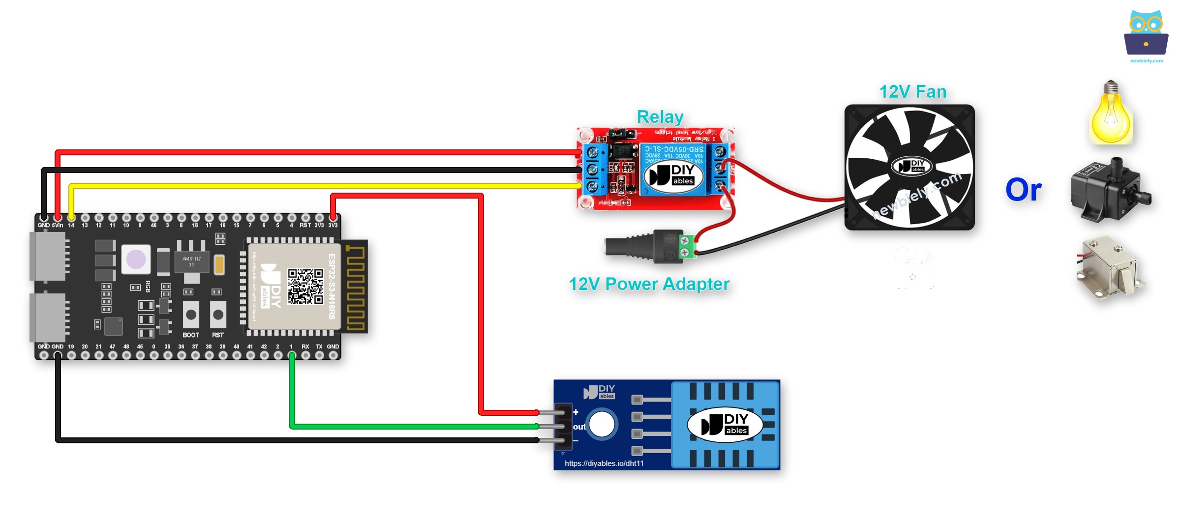
This image is created using Fritzing. Click to enlarge image
If the project will run for a long time, or sit inside a box, it is better to fix the wires with screws. You can plug the ESP32 S3 into a Screw Terminal Block for ESP32 S3 and connect the wires to its screw terminals. Below is the wiring diagram with the screw terminal board.
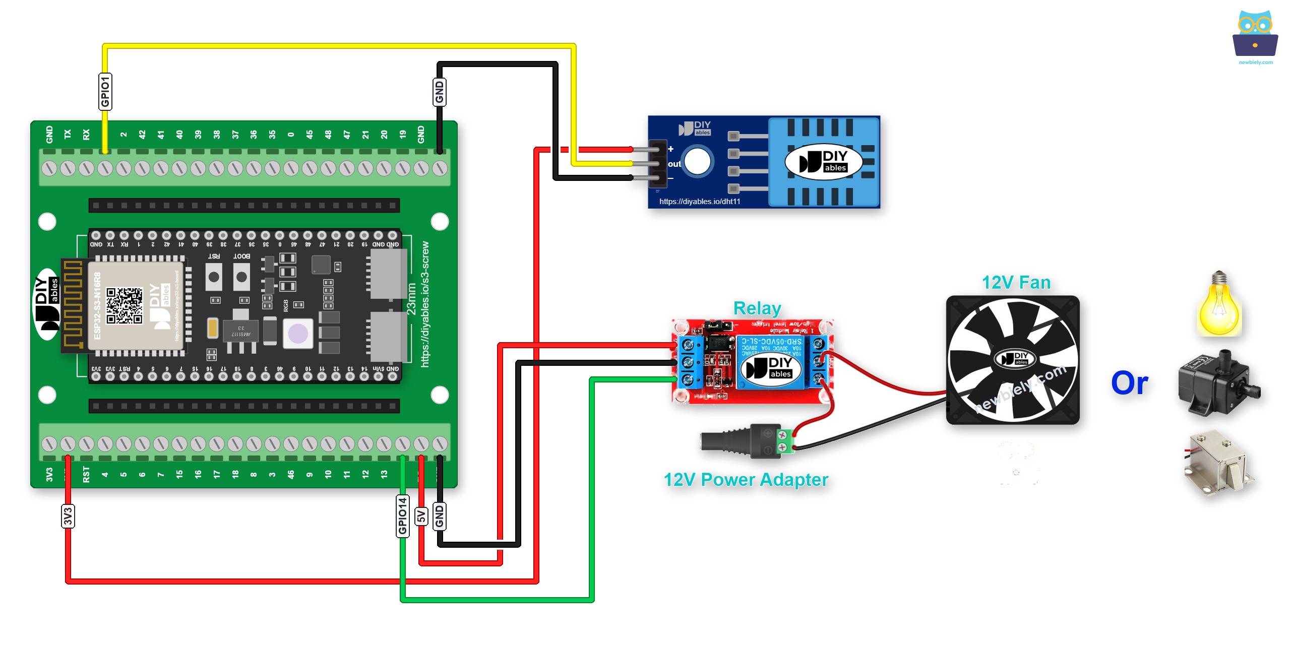
This image is created using Fritzing. Click to enlarge image
You can also use a GPIO Breakout Board for ESP32 S3. It gives each GPIO its own S, 3.3V and GND pins, so module wires plug straight in:
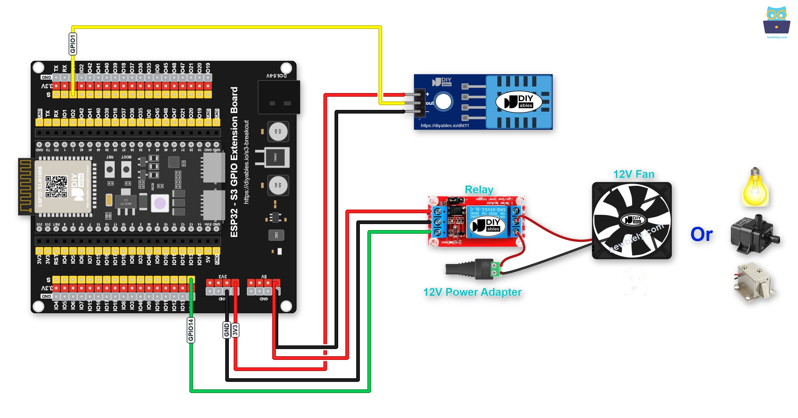
This image is created using Fritzing. Click to enlarge image
Safety Notes
Never connect mains voltage (110V/220V AC) to this circuit unless your relay module is rated for it and you are confident working with high-voltage wiring; always use a low-voltage load such as a 12V fan when prototyping. Ensure that the relay module's VCC and GND are connected to the ESP32 S3's 5V and GND rails respectively, and keep the high-voltage load wiring away from the breadboard and jumper wires to prevent accidental contact.
| Component | Pin | ESP32 S3 Pin |
|---|---|---|
| DHT11 Sensor | VCC | 3.3V or 5V |
| DHT11 Sensor | GND | GND |
| DHT11 Sensor | DATA | GPIO1 |
| Relay Module | VCC | 5V |
| Relay Module | GND | GND |
| Relay Module | IN | GPIO14 |
ESP32 S3 Code - DHT11 Sensor - Relay
The following code reads temperature from the DHT11 sensor on every loop iteration and compares it against two configurable thresholds: an upper threshold that switches the relay on and a lower threshold that switches it off. Using two separate thresholds instead of one prevents the relay from rapidly toggling when the temperature hovers near a single setpoint, a technique known as hysteresis that greatly extends relay life in real-world deployments.
In the above code, the ESP32 S3 turns on the relay when the temperature exceeds 25 °C and keeps it on until the temperature falls below 20 °C, creating a 5 °C hysteresis band that prevents rapid switching.
Detailed Instructions
- New to ESP32 S3? Complete our Getting Started with ESP32 S3 guide first.
- Wire the DHT11 sensor and relay module to the ESP32 S3 following the wiring diagram above.
- Connect the ESP32 S3 board to your PC using a USB Type-C cable.
- Open Arduino IDE on your PC.
- Select the correct ESP32 S3 board and COM port from the Tools menu.
- Click the Libraries icon on the left bar of the Arduino IDE.
- Type "DHT" in the search box, then look for the DHT sensor library by Adafruit.
- Click the Install button to install the library.
- Search for DHT sensor library created by Adafruit and click the Install button.
- A window appears asking you to install dependencies for the library.
- Click Install All to install all required dependencies.
- Copy the above code and paste it into Arduino IDE.
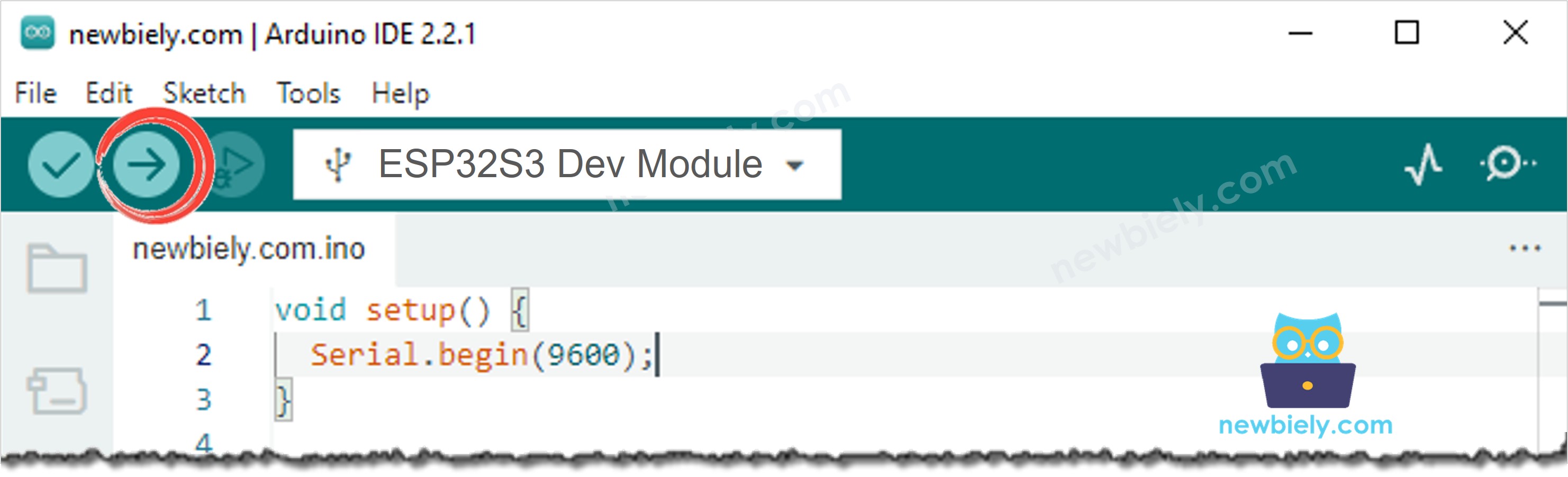
- Click the Upload button to compile and upload the code to your ESP32 S3.
- Open the Serial Monitor at 9600 baud to observe live temperature readings and relay state changes.
- Apply gentle warmth to the DHT11 sensor (such as holding it near a warm cup) until the temperature exceeds 25 °C and watch the relay click on.
- Move the sensor away from the heat source and watch the relay click off once the temperature drops below 20 °C.
- Pro Tip: Adjust the TEMP_HIGH_THRESHOLD and TEMP_LOW_THRESHOLD constants in the code to match the specific temperature range your application requires — for a single fixed setpoint, simply set both constants to the same value.
Serial Monitor Output
The following Serial Monitor output shows the ESP32 S3 reading temperature from the DHT11 sensor and switching the relay based on the configured thresholds. Each line is timestamped so you can verify the polling rate and observe exactly when the relay state changes in response to rising or falling temperature.
Application and Project Ideas
Once you have the ESP32 S3 automatically switching a relay based on DHT11 temperature readings, you can adapt this project into a wide range of practical control systems for home, agriculture, and industry.
- Automatic cooling fan: Connect a 12V fan to the relay so it switches on whenever a room, enclosure, or server cabinet gets too warm.
- Greenhouse heater controller: Activate a heater relay when the greenhouse temperature drops below a minimum threshold to protect plants from frost.
- Smart incubator: Maintain a precise temperature band inside an egg incubator by toggling a heat lamp relay based on DHT11 readings.
- Server room thermal protection: Trigger an alarm relay or alert system if the server room temperature climbs above a safe operating limit.
- Food storage monitor: Control a cooling relay in a refrigeration unit to maintain the optimal storage temperature for perishable goods.
- IoT thermal logger: Combine the relay control logic with Wi-Fi so the ESP32 S3 also publishes temperature readings and relay events to a cloud dashboard for remote monitoring.
Video Tutorial
Watch the step-by-step video walkthrough for this ESP32 S3 project below.
Challenge Yourself
Now that you can automatically switch a relay based on DHT11 temperature readings with your ESP32 S3, try these progressively harder challenges to deepen your understanding and extend the project into something more capable.
- Beginner: Modify the sketch to also read humidity from the DHT11 and print both temperature and humidity to the Serial Monitor on every update cycle.
- Beginner: Add an LED indicator that lights up whenever the relay is active so you can see the relay state at a glance without opening the Serial Monitor.
- Intermediate: Add a second relay controlled by humidity readings so the system can independently manage both a heater (for temperature) and a humidifier (for humidity).
- Intermediate: Implement a non-blocking polling loop using millis() instead of delay() so the ESP32 S3 can handle other tasks while still monitoring the sensor.
- Advanced: Add a small OLED or LCD display that shows the current temperature, the relay state, and the active thresholds, giving the system a self-contained user interface.
- Advanced: Extend the project with Wi-Fi and an MQTT broker so the upper and lower thresholds can be changed remotely from a phone or dashboard without re-uploading the sketch.