Communication between two ESP8266
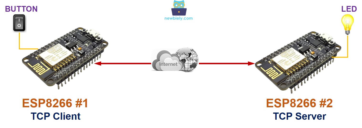
This guide shows you how to establish a connection between two ESP8266 devices using TCP/IP over WiFi and exchange data. One ESP8266 will function as a TCP client, while the other will act as a TCP server. We'll delve into this process through an example:
- ESP8266 #1 will connect to a button and serve as the TCP client.
- ESP8266 #2 will connect to an LED and function as the TCP server.
- Both ESP8266 devices will connect to each other over the internet.
- When the button on ESP8266 #1 is pressed, it will trigger the LED on ESP8266 #2 to turn on.
Hardware Preparation
| 2 | × | ESP8266 NodeMCU | |
| 2 | × | Micro USB Cable | |
| 1 | × | Recommended: Screw Terminal Expansion Board for ESP8266 |
Or you can buy the following kits:
| 1 | × | DIYables Sensor Kit (18 sensors/displays) |
Additionally, some of these links are for products from our own brand, DIYables .
Communication between two ESP8266 - Overview
Let us think of a particular example: ESP8266 #1 interacting with ESP8266 #2. There are numerous ways to enable communication between the two ESP8266. We can select one of them based on the distance of communication. The table below displays some methods and the corresponding communication range.
| Methods | Range |
|---|---|
| I2C | very short |
| SPI | very short |
| UART (TTL) | very short |
| UART (RS-232/485/422) | short |
| Bluetooth | short |
| LoRa | long |
| Ethernet/WiFi | unlimited(*) |
※ NOTE THAT:
- If two ESP8266 are connected to the Internet, the communication range is unrestricted.
- However, if two ESP8266 are not connected to the Internet, but instead connected in the same LAN network, their communication range is confined to that local area network.
Among the methods mentioned above, this tutorial uses WiFi to enable communication between two ESP8266 as it allows for an unrestricted range of communication.
Communication between two ESP8266 via local LAN or Internet
Two ESP8266 can communicate with one another through WiFi when:
- They are in the same Local Area Network (LAN), and an Internet connection is not necessary
- They are in different LANs, and an Internet connection is needed
No matter if two ESP8266 are connected within a local LAN network or via the Internet, there are two ways of communication:
- Directly between the two ESP8266
- Through a centralized server (e.g. an MQTT server). Refer to Communication between two ESP8266 via MQTT
When it comes to direct communication, typically one ESP8266 is the TCP client and the other is the TCP server.
In the instance of utilizing a centralized server for communication, typically both ESP8266 act as TCP clients.
When deciding on an application protocol for communication between two ESP8266, we have several options to choose from:
- Self-defined protocol over raw TCP
- Modbus TCP
- HTTP
- Telnet
- SSH
- MQTT (which requires a centralized server)
Example Application
Let's make a reality of the following program: A button/switch attached to ESP8266 #1 will be used to turn on and off an LED connected to ESP8266 #2 through WiFi.
As stated previously, there are a few application protocols available. To simplify this example, we will create our own protocol (a self-defined protocol).
Self-defined Protocol
Let us set up a straightforward protocol:
- Establish a TCP connection between ESP8266 #1 and ESP8266 #2
- ESP8266 #1:
- Behave as a TCP client, initiating the TCP connection to ESP8266 #2
- When the switch is flipped to ON, send a byte (command) with value 1 to ESP8266 #2.
- When the switch is flipped to OFF, send a byte (command) with value 0 to ESP8266 #2.
- ESP8266 #2:
- Serve as TCP server, listening for TCP connection requests from ESP8266 #1
- If the received byte is 1, turn ON the LED
- If the received byte is 0, turn OFF the LED
- ESP8266 #1 - Wiring diagram between ESP8266 and button
- ESP8266 #2 - Wiring diagram between ESP8266 and LED
- Check out the how to setup environment for ESP8266 on Arduino IDE tutorial if this is your first time using ESP8266.
- Wire the components as shown in the diagram.
- Connect two ESP8266 boards to your computer using a USB cable.
- Open the Arduino IDE (called Arduino IDE #1).
- Open the Arduino IDE (called Arduino IDE #2).
- Choose the correct ESP8266 board, such as (e.g. NodeMCU 1.0 (ESP-12E Module)), and its respective COM port.
- Install the ezButton library on Arduino IDE.
- Copy the ESP8266 #1 code, paste it to Arduino IDE #1 and save it (named ESP8266-1).
- Copy the ESP8266 #2 code, paste it to Arduino IDE #2 and save it (named ESP8266-2).
- Upload ESP8266 #2 code to ESP8266 #2 first.
- Open the Serial Monitor on Arduino IDE #2, get the TCP Server IP address.
- Change the TCP Server IP address in the code of ESP8266 #1.
- Upload ESP8266 #1 code to ESP8266 #1
- Open the Serial Monitor on the Arduino IDE #1.
- Press and hold the button on ESP8266 #1 and observe the LED's state on ESP8266 #2 (it should be ON).
- Release the button on ESP8266 #1 and observe the LED's state on ESP8266 #2 (it should be OFF).
- Press, hold, and release the button several times.
- Check the output on Serial Monitor #1:
- Check the output on Serial Monitor #2:
Wiring Diagram
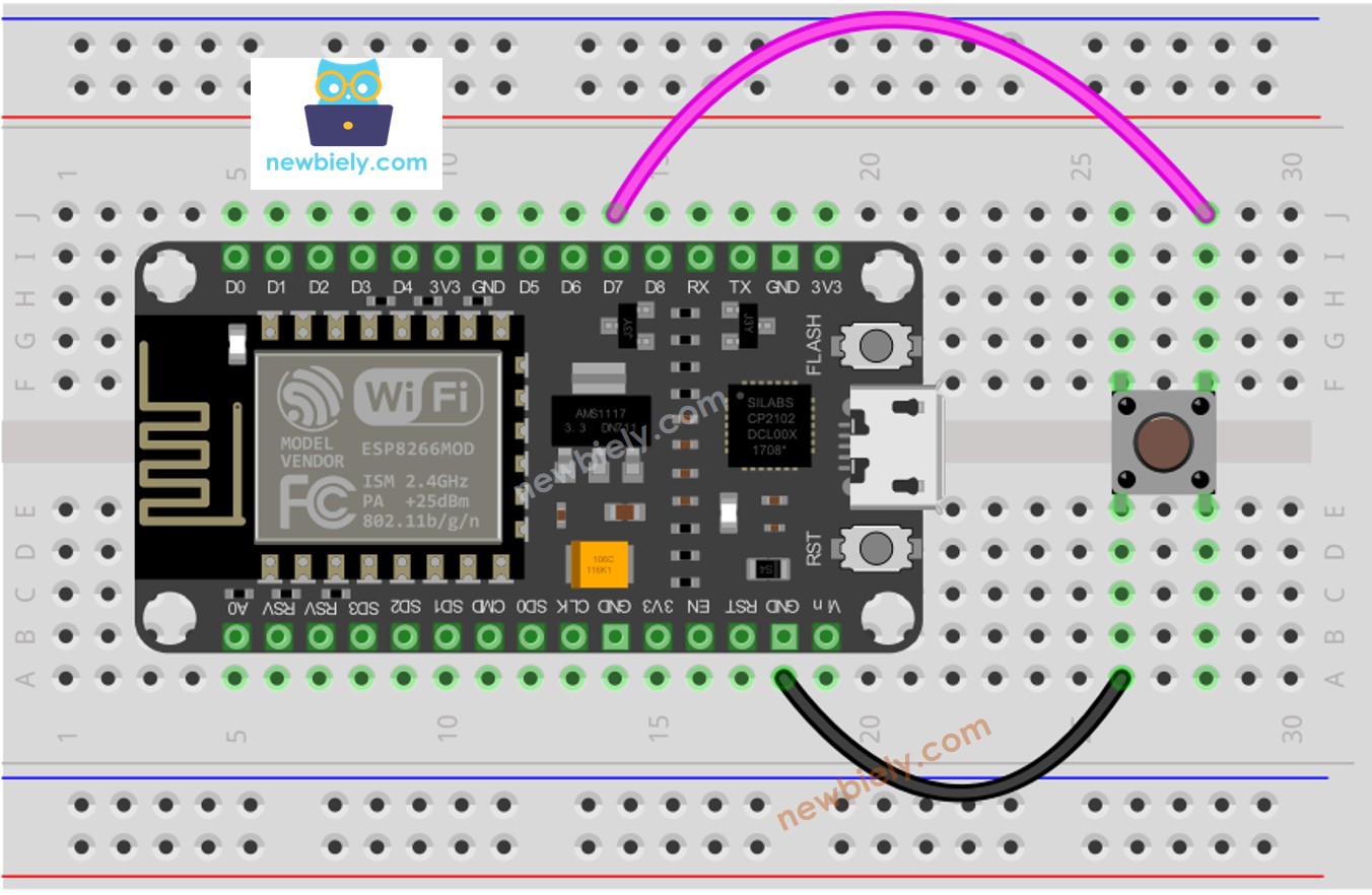
This image is created using Fritzing. Click to enlarge image
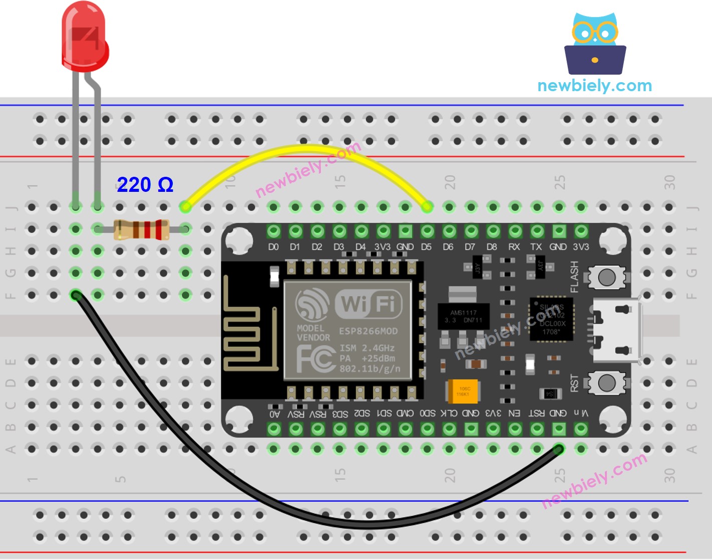
This image is created using Fritzing. Click to enlarge image
See more in ESP8266's pinout and how to supply power to the ESP8266 and other components.
ESP8266 Code for ESP8266 #1
ESP8266 Code for ESP8266 #2
Detailed Instructions
To get started with ESP8266 on Arduino IDE, follow these steps:
Video Tutorial
How to connect two ESP8266 via Internet
There are two types of IP address: private and public. The IP address typically used in a home network is a private one.
It is simple to recognize a private IP address. There are three formats of private IP address: 10.x.x.x, 172.16.x.x, 192.168.x.x
It is not important to utilize the private IP address in the following scenarios:
- When two ESP8266 are within the same local area network, regardless of whether they are communicating directly or through a centralized server, and regardless of whether the LAN is connected to the internet or not.
- When two ESP8266 are in separate local area networks and are communicating with one another through a centralized server.
In the case of two ESP8266 being in different LAN networks and communicating with each other directly, the ESP8266 TCP client can utilize a private IP address. However, the ESP8266 TCP server must use either:
- A public IP address
- A private IP address with "Port Forwarding" on the Router/Access Point
The technique of "Port Forwarding" varies from router/AP to router/AP. This tutorial does not cover this topic.