ESP8266 - RS422
In this guide, we will delve into how to set up RS422 communication with ESP8266. We'll go through the following steps thoroughly:
- Connecting ESP8266 to the TTL to RS422 module.
- Programming ESP8266 to receive data from the TTL to RS422 module.
- Programming ESP8266 to send data to the TTL to RS422 module.
- Sending data between your PC and ESP8266 through RS422 bidirectionally.
The tutorial also provides the instruction for both Hardware Serial and SoftwareSerial.
Hardware Preparation
Or you can buy the following kits:
| 1 | × | DIYables Sensor Kit (18 sensors/displays) |
Additionally, some of these links are for products from our own brand, DIYables .
Overview of TTL to RS422 Module
When utilizing serial communication on ESP8266 through functions like Serial.print(), Serial.read(), and Serial.write(), the ESP8266 transmits data via the TX pin and receives data through the RX pin. These pins operate at TTL level, meaning the signals they handle have limited range. Thus, for serial communication over longer distances, it becomes necessary to convert the TTL signal to RS232, RS422, or RS422 signal standards.
In this tutorial, we'll delve into the utilization of RS422 (also known as RS-422) with ESP8266 by employing a TTL to RS422 module. This module facilitates the conversion of TTL signals to RS422 signals and vice versa.
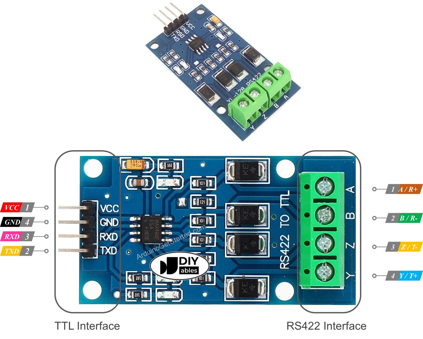
Pinout
The RS422 to TTL module has two interfaces:
- The TTL interface (connnected to ESP8266) includes 4 pins
- VCC pin: power pin, needs to be connected to VCC (5V, or 3.3V)
- GND pin: power pin, needs to be connected to GND (0V)
- RXD pin: data pin, needs to be connected a TX pin of ESP8266
- TXD pin: data pin, needs to be connected a RX pin of ESP8266
- The RS422 interface comprises the following pins:
- A (R+) pin: RX+ pin of the module, connect this pin to TX+ pin (T+ or Y pin) of the other RS422 device.
- B (R-) pin: RX- pin of the module, connect this pin to TX- pin (T- or Z pin) of the other RS422 device.
- Y (T+) pin: TX+ pin of the module, connect this pin to RX+ pin (R+ or A pin) of the other RS422 device.
- Z (T-) pin: TX- pin of the module, connect this pin to RX- pin (R- or B pin) of the other RS422 device.
Wiring Diagram
- Wiring diagram if using hardware serial
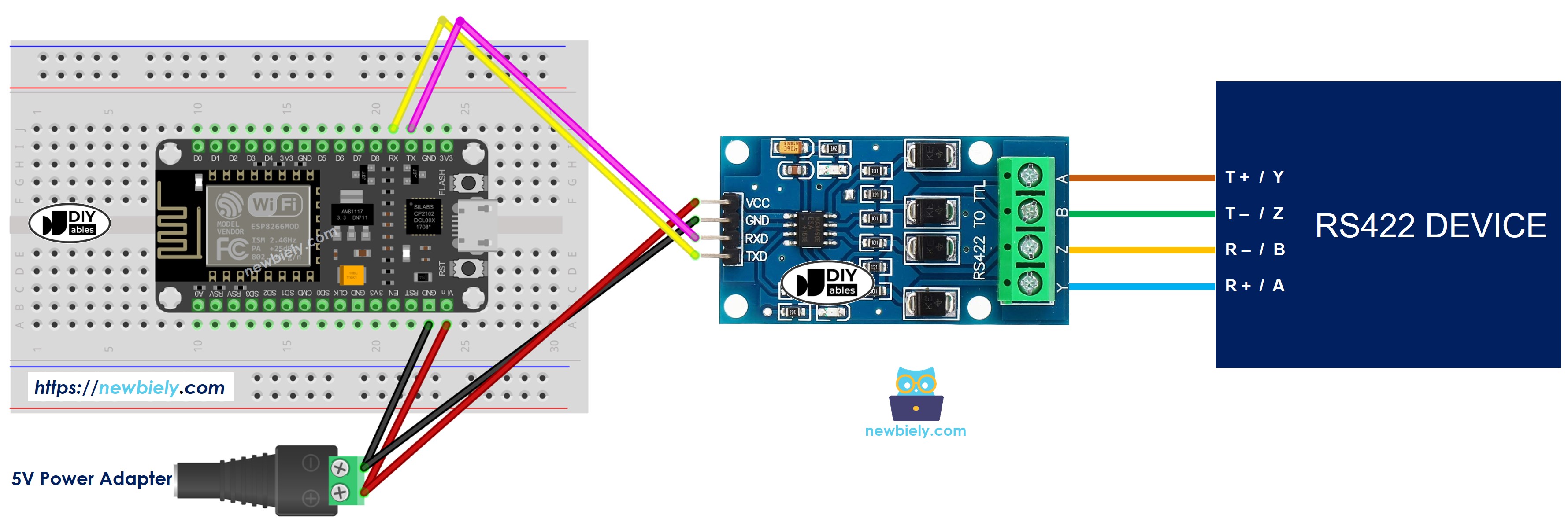
This image is created using Fritzing. Click to enlarge image
- Wiring diagram if using software serial
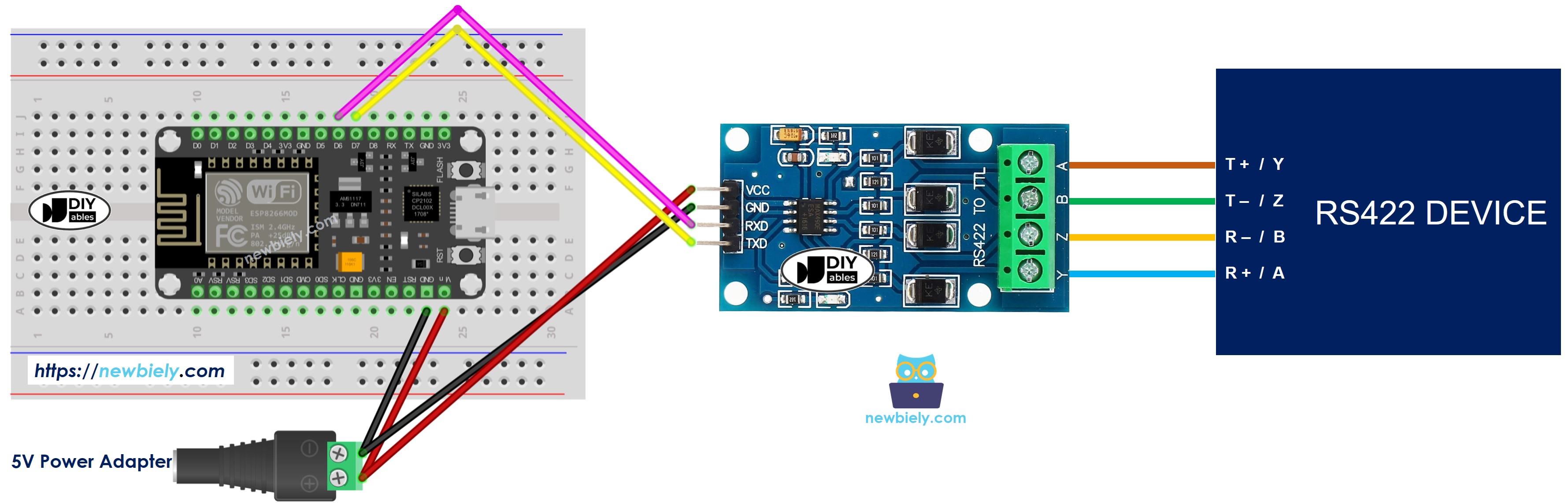
This image is created using Fritzing. Click to enlarge image
See more in ESP8266's pinout and how to supply power to the ESP8266 and other components.
How To Program ESP8266 to use the RS422 module
To get started with ESP8266 on Arduino IDE, follow these steps:
- Check out the how to setup environment for ESP8266 on Arduino IDE tutorial if this is your first time using ESP8266.
- Initializes the Serial interface:
- If you use SoftwareSerial, you need to include the library and declare a SoftwareSerial object:
- To read data come from RS422, you can use the following functions:
- To write data to RS422, you can use the following functions:
- And more functions to use with RS422 in Serial reference
ESP8266 Code for Hardware Serial
ESP8266 Code for Software Serial
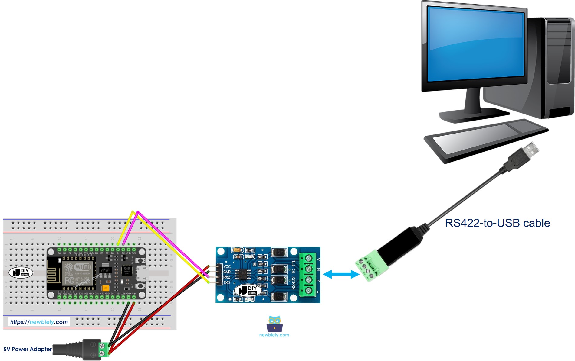
Testing
You can do a test by sending data from your PC to ESP8266 via RS-422 and vice versa. To do it, follow the below steps:
- Connect ESP8266 to your PC via RS422-to-USB cable as below:
- Open the Serial Terminal Program and configure the Serial parameters (COM port, baurate...)
- Type some data from the Serial Termial to send it to ESP8266.
- If successful, you will see the echo data on the Serial Terminal.