ESP8266 - Limit Switch
This tutorial instructs you how to use ESP8266 with the limit switch. In detail, we will learn:
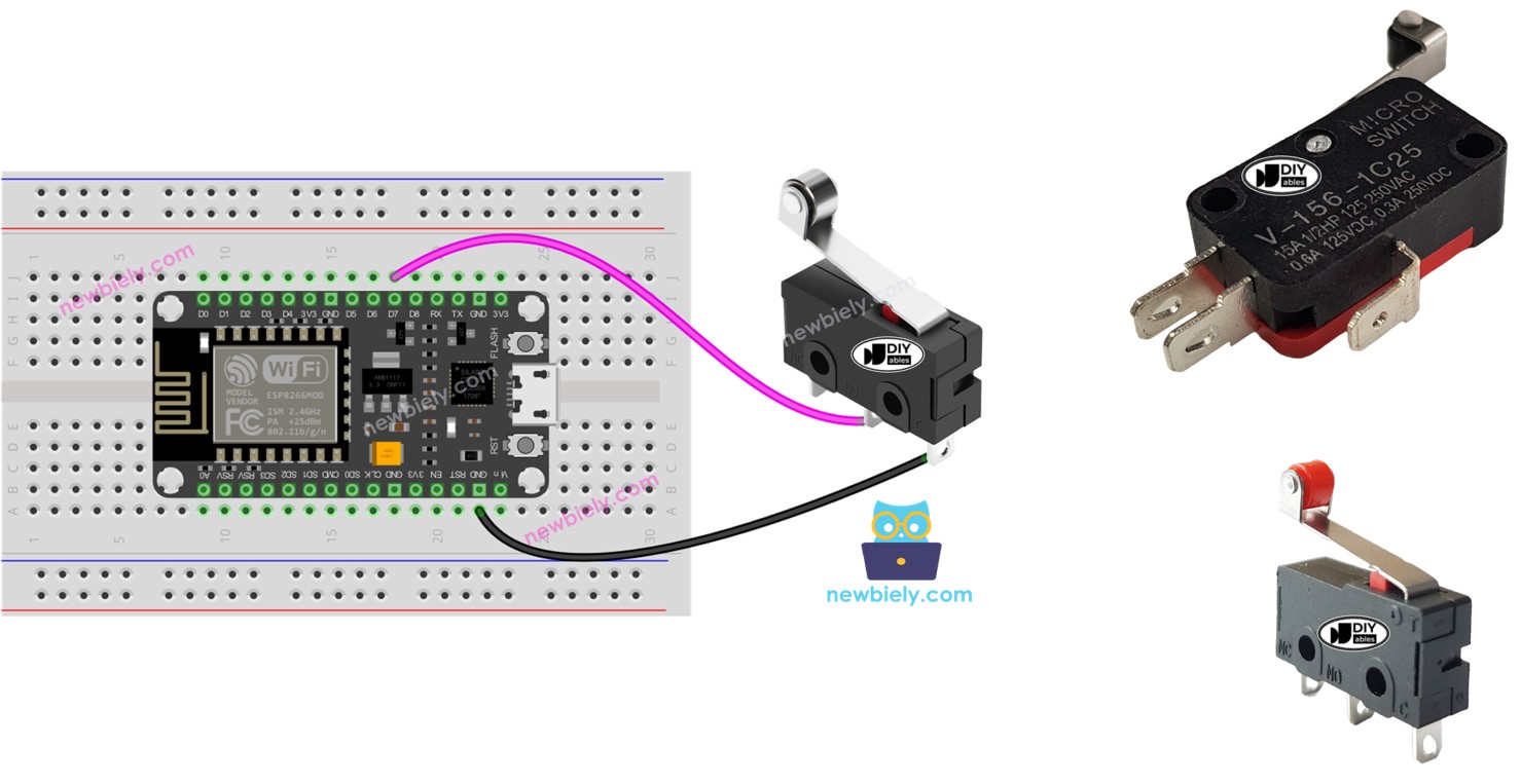
- How to connect the ESP8266 to the limit switch.
- How to program the ESP8266 to read the state of the limit switch.
- How to program the ESP8266 to check if the limit switch is touched or not.
Hardware Preparation
Or you can buy the following kits:
| 1 | × | DIYables Sensor Kit (18 sensors/displays) |
Additionally, some of these links are for products from our own brand, DIYables .
Overview of Limit Switch
It is referred to as Limit Switch because its primary purpose is to detect when a moving object has reached a limit.
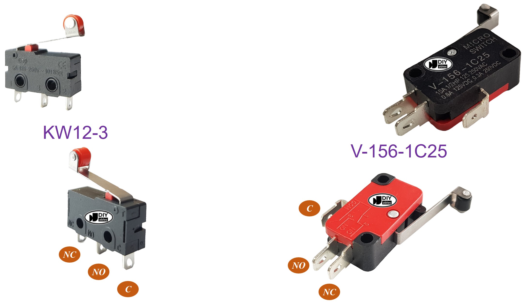
The Limit Switch Pinout
There exist various types of limit switches, yet the most widely favored ones are the KW12-3 and V-156-1C25. Each of these types features three pins:
- C: This is the common pin and is used for both normally open and normally closed modes.
- NO: This is the normally open pin and is used only in the normally open mode.
- NC: This is the normally closed pin and is used only in the normally closed mode.
How It Works
Although the limit switch has three pins, a typical application usually utilizes only two pins: the C pin and one of the other two. Consequently, there are four different ways to use the limit switch. The following is a wiring table for the limit switch and the reading state on ESP8266 for all four methods:
| C pin | NO pin | NC pin | ESP8266 Input Pin's State | |
|---|---|---|---|---|
| 1 | GND | ESP8266 Input Pin (with pull-up) | not connected | HIGH when untouched, LOW when touched |
| 2 | GND | not connected | ESP8266 Input Pin (with pull-up) | LOW when untouched, HIGH when touched |
| 3 | VCC | ESP8266 Input Pin (with pull-down) | not connected | LOW when untouched, HIGH when touched |
| 4 | VCC | not connected | ESP8266 Input Pin (with pull-down) | HIGH when untouched, LOW when touched |
For every method, we can interchange the GND pin and the ESP8266 Input Pin. Consequently, there are eight possible ways to connect an ESP8266 to a limit switch.
We must select one of the four options presented. The remainder of the tutorial will use the first method.
Wiring Diagram
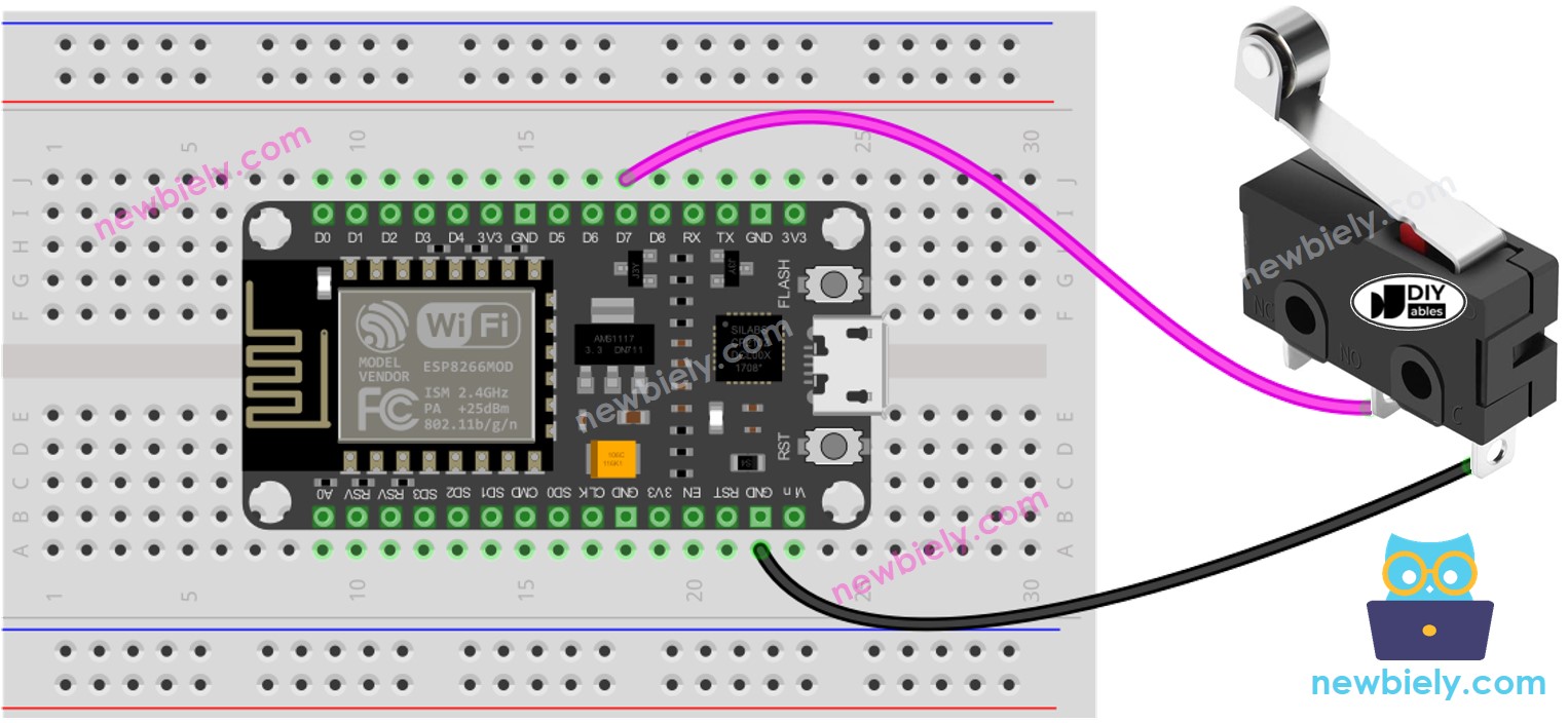
This image is created using Fritzing. Click to enlarge image
See more in ESP8266's pinout and how to supply power to the ESP8266 and other components.
For a secure and reliable wiring connection, we suggest using a Soldering Iron to solder the wires and pins of the limit switch together. After that, cover the connection with Heat Shrink Tube for extra safety.
ESP8266 Code - Limit Switch
Similar to a button, debouncing is also necessary for a limit switch (for more information, see Why needs debounce for the button/limit switch?). This can make programming complex. Fortunately, the ezButton library supports the debouncing function and has an internal pull-up register, which makes it easier to program the button.
※ NOTE THAT:
Two common applications exist with limit switch:
- The first: if the switch is in the TOUCHED state, a certain action should be taken. Conversely, if the input is UNTOUCHED, a different action should be done.
- The second: if the switch is changed from UNTOUCHED to TOUCHED (or vice versa), a specific action should be executed.
Detailed Instructions
To get started with ESP8266 on Arduino IDE, follow these steps:
- Check out the how to setup environment for ESP8266 on Arduino IDE tutorial if this is your first time using ESP8266.
- Wire the components as shown in the diagram.
- Connect the ESP8266 board to your computer using a USB cable.
- Open Arduino IDE on your computer.
- Choose the correct ESP8266 board, such as (e.g. NodeMCU 1.0 (ESP-12E Module)), and its respective COM port.
- Do the wiring as indicated in the diagram.
- Connect the ESP8266 to a computer using a USB cable.
- Open the Arduino IDE.
- Install the ezButton library, instructions can be found here.
- Select the correct board and port.
- Click the Upload button on the Arduino IDE to compile and upload the code to the ESP8266.
- Press and release the Limit Switch.
- Check out the result on the Serial Monitor.