ESP8266 - Obstacle Sensor
This tutorial instructs you how to use ESP8266 with the infrared obstacle avoidance sensor. In detail, we will learn:
- How to connect the ESP8266 to the infrared obstacle avoidance sensor.
- How to program the ESP8266 to read the state of the infrared obstacle avoidance sensor.
- How to program the ESP8266 to detect obstacles.
Hardware Preparation
Or you can buy the following kits:
| 1 | × | DIYables Sensor Kit (18 sensors/displays) |
Additionally, some of these links are for products from our own brand, DIYables .
Overview of IR Obstacle Avoidance Sensor
The infrared obstacle sensor is designed to detect the presence of any obstacle in its path by using an infrared signal. It has a detection range of 2cm to 30cm, which can be adjusted with a built-in potentiometer.
The Infrared Obstacle Avoidance Sensor Pinout
The IR obstacle avoidance sensor has three pins:
- GND pin: must be connected to GND (0V)
- VCC pin: must be connected to VCC (5V or 3.3v)
- OUT pin: is an output pin, LOW when an obstacle is present, HIGH when there is none. This pin must be connected to an ESP8266 input pin.
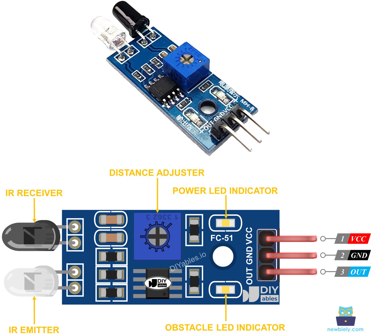
How It Works
The infrared obstacle sensor module has a built-in infrared transmitter and receiver. The transmitter emits an infrared signal. The receiver looks for the reflected signal to detect if an object is present or not. The OUT pin indicates the presence of an obstacle:
- If something is blocking the sensor, the OUT pin will be LOW
- If nothing is blocking the sensor, the OUT pin will be HIGH
※ NOTE THAT:
During shipment, there is a possibility that this sensor may become deformed, which can result in malfunctioning. If you find that the sensor is not working properly, try adjusting the IR transmitter and receiver to align them parallel to each other.
Wiring Diagram
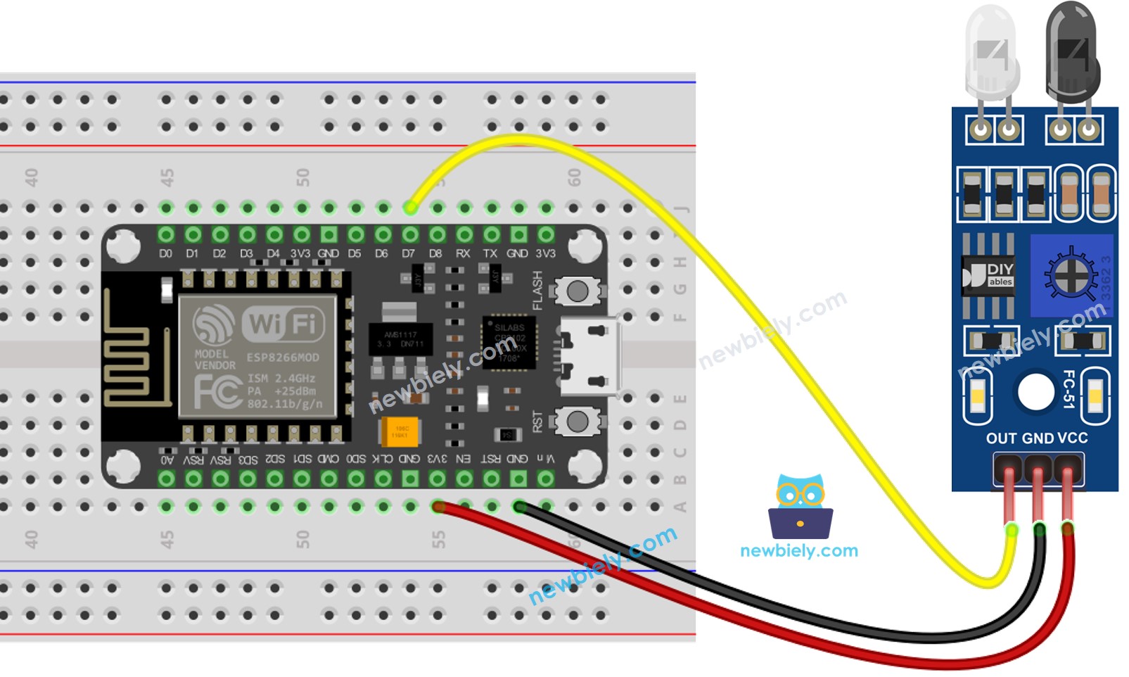
This image is created using Fritzing. Click to enlarge image
See more in ESP8266's pinout and how to supply power to the ESP8266 and other components.
How To Program For IR Obstacle Avoidance Sensor
- Initializes the ESP8266 pin to the digital input mode by utilizing the pinMode() function. For example, pin D7:
- Read the status of the ESP8266 pin through the digitalRead() function.
ESP8266 Code
There are two approaches to programming for an obstacle avoidance application:
- Taking action when the obstacle is present or absent
- Taking action when the obstacle is detected or cleared
ESP8266 code for checking if the obstacle is present
Detailed Instructions
To get started with ESP8266 on Arduino IDE, follow these steps:
- Check out the how to setup environment for ESP8266 on Arduino IDE tutorial if this is your first time using ESP8266.
- Wire the components as shown in the diagram.
- Connect the ESP8266 board to your computer using a USB cable.
- Open Arduino IDE on your computer.
- Choose the correct ESP8266 board, such as (e.g. NodeMCU 1.0 (ESP-12E Module)), and its respective COM port.
- Copy the code and open it in Arduino IDE.
- Click the Upload button to send the code to ESP8266.
- Place an obstacle in front of the sensor and then take it away.
- Check the result on Serial Monitor.
ESP8266 code for detecting obstacle
Detailed Instructions
- Wire the components as shown in the diagram.
- Connect the ESP8266 board to your computer using a USB cable.
- Open Arduino IDE on your computer.
- Choose the correct ESP8266 board, such as (e.g. NodeMCU 1.0 (ESP-12E Module)), and its respective COM port.
- Copy the code above and open it in the Arduino IDE.
- Click the Upload button in the Arduino IDE to send the code to the ESP8266.
- Place an obstacle in front of the sensor for a while, then remove it.
- Check the results in the Serial Monitor.