ESP8266 - 2-Channel Relay Module
This tutorial instructs you how to use ESP8266 to control a 2-channel relay module. In detail, we will learn:
- The pinout of a 2-channel relay module
- How to connect ESP8266 to a 2-channel relay module
- How to program ESP8266 to control the 2-channel relay module
When we want to control two high-voltage devices such as pumps, fans, or actuators, we have two choices. We can either use multiple relay modules or opt for a simpler solution. The simpler way is to use a 2-channel relay module, which is a single board that already has two relays integrated into it. This approach makes the setup easier and more convenient for controlling both devices.
Hardware Preparation
Or you can buy the following kits:
| 1 | × | DIYables Sensor Kit (18 sensors/displays) |
Additionally, some of these links are for products from our own brand, DIYables .
Overview of 2-Channel Relay Module
Pinout
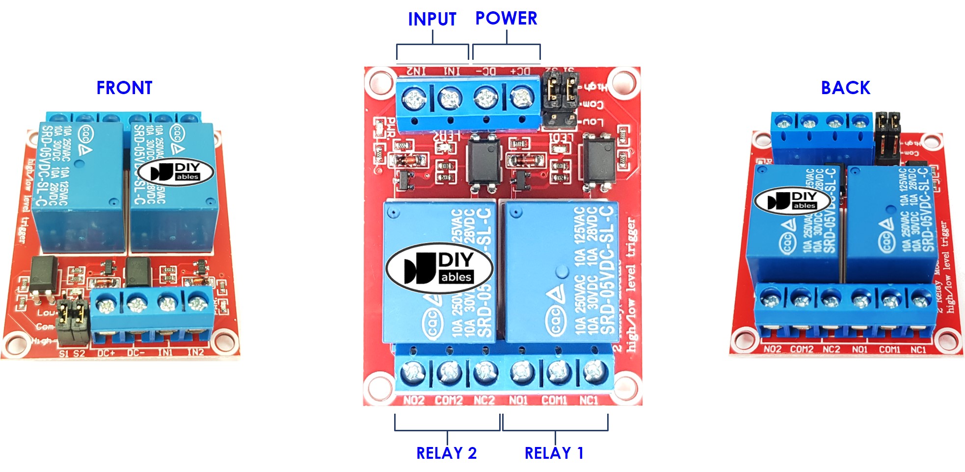
A 2-channel relay module has the following pins:
- Power pins for relay boards
- DC+: connect this pin to 5V pin of power supply
- DC-: connect this pin to the GND pin of the power supply and also to the GND pin of the ESP8266
- Signal pins:
- IN1: this pin receives the control signal from ESP8266 to control relay 1 on the module
- IN2: this pin receives the control signal from ESP8266 to control relay 2 on the module
- Output pins: NCx (normally closed pin), NOx (normally open pin), COMx (common pin),
- NC1, NO1, COM1: These pins connect to a high-voltage device that is controlled by relay 1
- NC2, NO2, COM2: These pins connect to a high-voltage device that is controlled by relay 2
- How to connect relay to high-voltage devices
- The terms normally closed and normally open
- The terms low-level trigger and high-level trigger
- How to control relay using ESP8266
Additionally, the 2-channel relay module includes 2 jumpers that allow you to choose between the low-level trigger and high-level trigger for each relay individually.
If you're interested in learning the fundamentals of relays, I recommend checking out the ESP8266 - Relay tutorial. The tutorial provides detailed information on:
Wiring Diagram
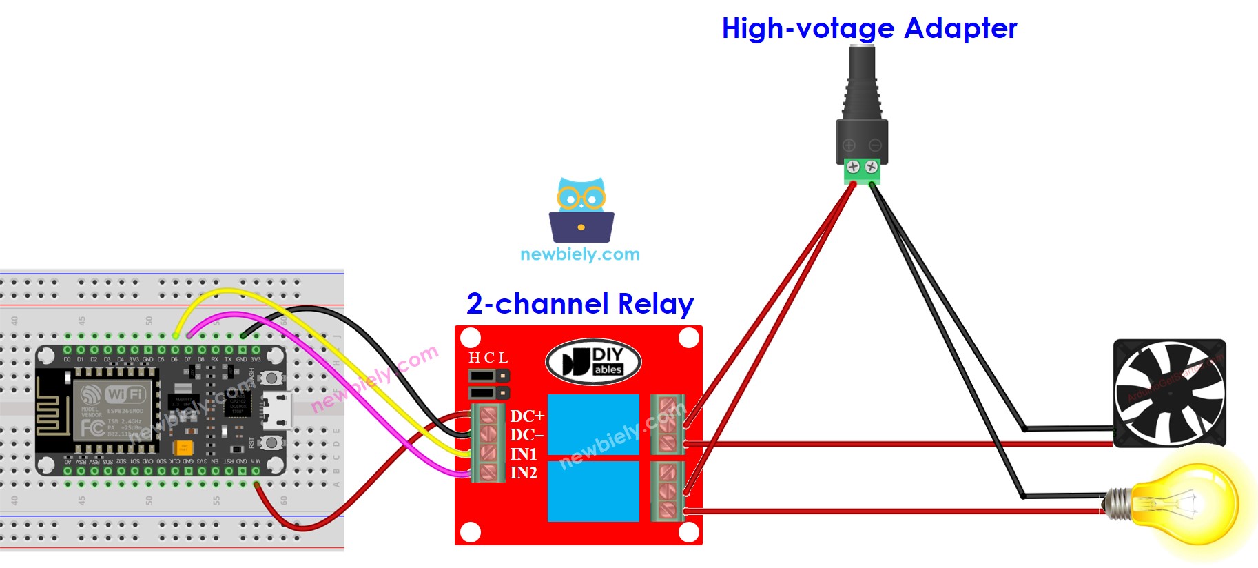
This image is created using Fritzing. Click to enlarge image
If you plan to use the 5V pins to power additional components, there's a chance that the relay module won't receive enough power. Therefore, it's essential to use a separate 5V power source specifically for the module.
So, we need to use three types of power sources:
- A 5V power adapter for ESP8266
- A 5V power adapter for the 2-channel relay module
- One or several higher-voltage power adapters (12VDC, 24VDC, 48VDC, 220AC...) for things that are controlled by the 2-channel relay module
Below is the wiring diagram using three power sources. The power supply for the ESP8266 (not shown in the image) can be connected either through a USB cable or a power jack.
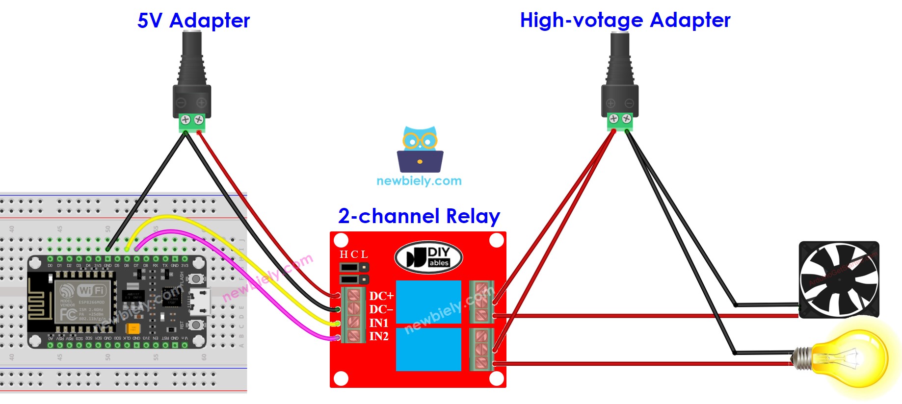
This image is created using Fritzing. Click to enlarge image
To reduce the number of power adapters required, we can simplify things by using a single 5V power supply for both the ESP8266 and the 2-channel relay module.
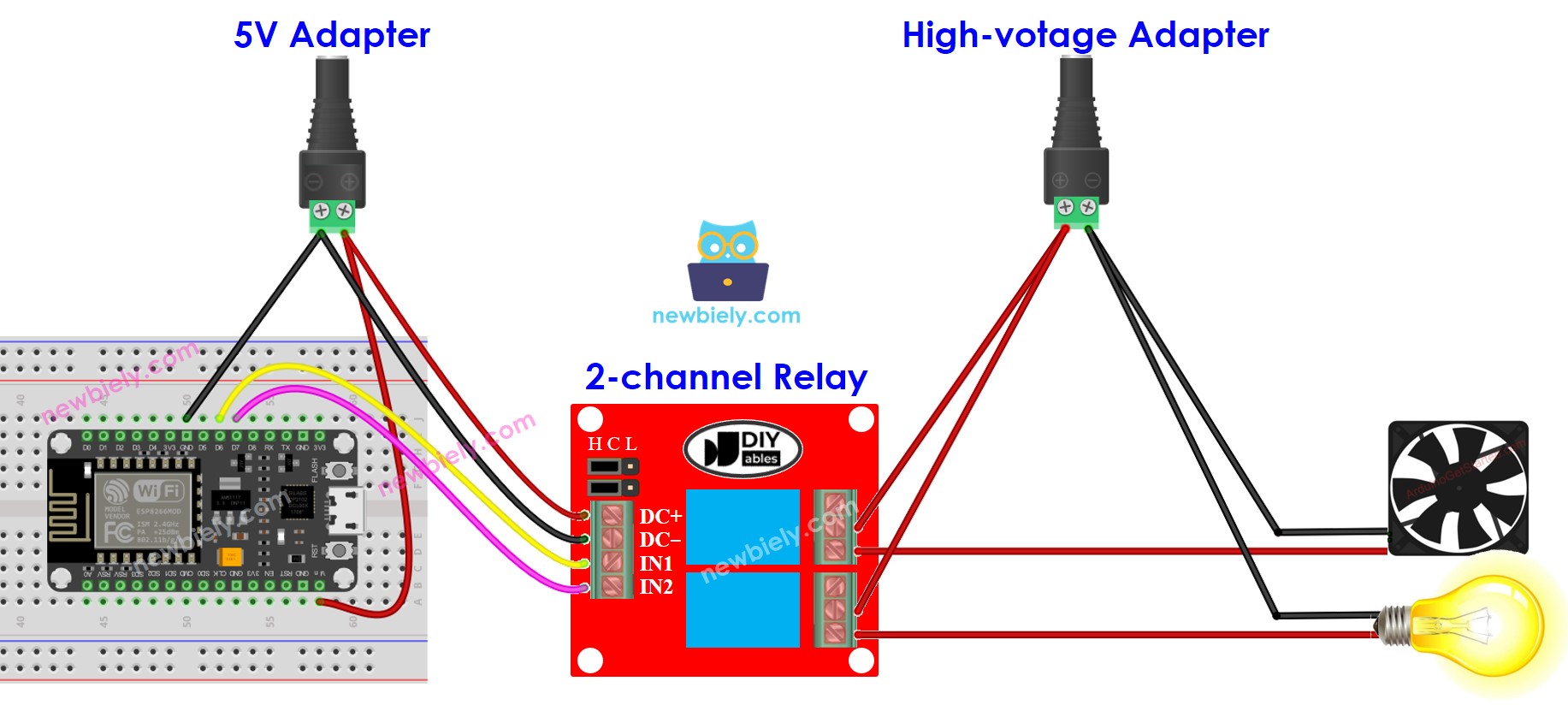
This image is created using Fritzing. Click to enlarge image
See more in ESP8266's pinout and how to supply power to the ESP8266 and other components.
※ NOTE THAT:
If the two devices controlled by a 2-channel relay module operate at the same voltage, we can utilize a single high-voltage power adapter to supply power to both devices. However, if the devices require different voltages, we can independently use separate high-voltage power adapters for each device.
How To Program For 2-Channel Relay Module
- Initializes the ESP8266 pin to the digital output mode by using pinMode() function.
- Control the relay's state by using digitalWrite() function.
ESP8266 Code
Detailed Instructions
- Copy the above code and open with Arduino IDE
- Click Upload button on Arduino IDE to upload code to ESP8266
- Listen the click sound on relays.
- Check out the result on the Serial Monitor.