ESP8266 - TM1637 4-Digit 7-Segment Display
Let's get your ESP8266 up and running with a TM1637 4-digit 7-segment display. The ESP8266 is a compact, affordable Wi-Fi microcontroller - perfect for lightweight IoT projects that need a simple numeric output.
Here is what we will cover:
- Wiring the TM1637 module to the ESP8266.
- Displaying integers, text strings, and temperature.
- Showing time in HH:MM format with a blinking colon.
- Setting individual digits and controlling brightness.
Hardware Preparation
Or you can buy the following kits:
| 1 | × | DIYables Sensor Kit (18 sensors/displays) |
Additionally, some of these links are for products from our own brand, DIYables .
Getting to Know the TM1637 Display Module
The TM1637 is a dedicated driver IC for 7-segment LED displays. It talks to the microcontroller through a 2-wire serial link (CLK and DIO) and handles all the LED multiplexing internally. Once you send data to the TM1637, the display keeps showing it until you change it.
What the module offers:
- 4 digits, 7 segments plus decimal point each
- Colon separator between digit 1 and 2
- 8 brightness levels, software-controllable
- Works at 3.3V - perfect for the ESP8266's logic level
- No continuous refresh needed
| Function | Pin |
|---|---|
| CLK | Clock signal |
| DIO | Data I/O |
| VCC | 3.3V or 5V |
| GND | Ground |
Connect CLK and DIO to any available GPIO pins on the ESP8266. Avoid GPIO0, GPIO2, and GPIO15 since those affect boot mode.
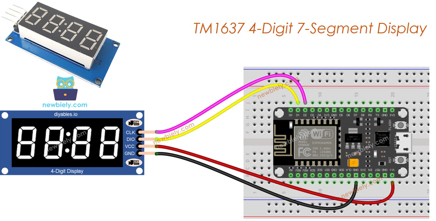
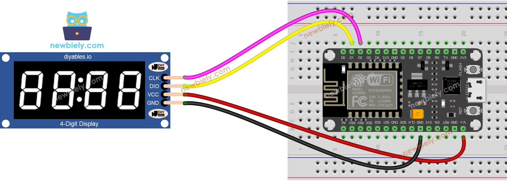
Wiring Diagram
Connect the TM1637 to the ESP8266 NodeMCU:
- CLK to D2
- DIO to D1
- VCC to 3.3V
- GND to GND
This image is created using Fritzing. Click to enlarge image
See more in ESP8266's pinout and how to supply power to the ESP8266 and other components.
Adding the Library
- Connect the ESP8266 to your computer with a USB cable.
- Open Arduino IDE. Select NodeMCU 1.0 (ESP-12E Module) as the board and pick the right port.
- Head to the Libraries section on the left.
- Look up "DIYables_4Digit7Segment_TM1637" and find the DIYables library.
- Tap Install.
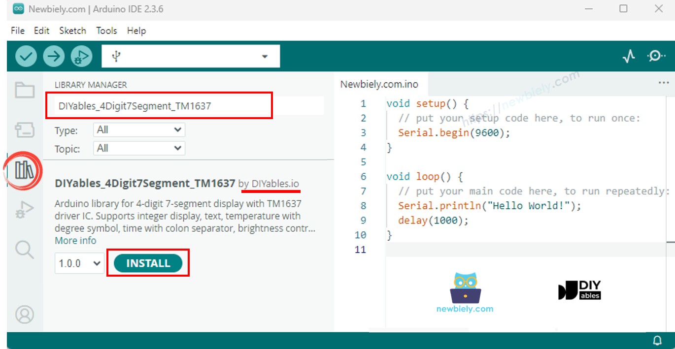
The library ships with everything it needs - no extra dependencies.
Quick Start Code
The shortest sketch to see results:
Create the display with the GPIO numbers for CLK and DIO, call begin(), and start displaying data right away.
Try It Out - Integer Display
Displays a series of integers including negative numbers and zero-padded values.
Run the Code
- Wire the TM1637 module to the ESP8266 as described above.
- Plug the ESP8266 into your computer via USB.
- In Arduino IDE, pick the board and port, paste the code, and press Upload.
- Open the Serial Monitor to check the output.
The display cycles through 0, 42, 1234, -5, -123, 9999, and then "0042" zero-padded.
Handy Methods
| Method | Purpose | How to Call |
|---|---|---|
| print(int) | Show an integer | display.print(1234) |
| print(int, true) | Show with leading zeros | display.print(42, true) |
| clear() | Clear the display | display.clear() |
Try It Out - Text and Temperature
Shows text strings and formatted temperature with the degree symbol.
Run the Code
- Wire and upload. Open the Serial Monitor.
Shows "HELP", "Hi", "COOL", "done", then "25°C" and "72°F".
Handy Methods
| Method | Purpose | How to Call |
|---|---|---|
| print(const char*) | Display text | display.print("HELP") |
| printTemperature(int, char) | Show temperature | display.printTemperature(25, 'C') |
| DEGREE | Degree character | display.DEGREE |
Try It Out - Time with Colon
Shows time in HH:MM format with the colon blinking every 500ms.
Run the Code
- Upload and watch "12:30" with the blinking colon.
Handy Methods
| Method | Purpose | How to Call | |
|---|---|---|---|
| printTime(int, int) | Display HH | MM | display.printTime(12, 30) |
| printTime(int, int, bool) | Control colon | display.printTime(12, 30, false) |
Try It Out - Blink Effect
Blinks the display using off() and on() while preserving content.
Run the Code
- Upload and observe "1234" blinking, then "HELP" blinking.
Handy Methods
| Method | Purpose | How to Call |
|---|---|---|
| off() | Turn display off | display.off() |
| on() | Turn display on | display.on() |
| setBrightness(int) | Set brightness 0-7 | display.setBrightness(4) |
Try It Out - Individual Digits
Sets each digit independently with numbers, characters, and the colon.
Run the Code
- Upload and see the digit combinations change.
Handy Methods
| Method | Purpose | How to Call |
|---|---|---|
| setNumber(int, int) | Set digit 0-9 | display.setNumber(0, 1) |
| setChar(int, char) | Set character | display.setChar(0, 'H') |
| setColon(bool) | Control colon | display.setColon(true) |
| setSegments(int, uint8_t) | Raw segments | display.setSegments(0, 0x76) |
If Something Is Not Working
- Display is blank: Double-check all four wires. Verify CLK and DIO GPIO numbers match between the code and the physical wiring.
- Wrong output: CLK and DIO may be swapped. Switch the two signal wires.
- Dim display: Call setBrightness(7) for full brightness.
- Upload fails: Some ESP8266 boards need you to press FLASH during upload. Also check that the correct board and port are selected.
Tip: The ESP8266 has limited GPIO pins. Double-check that none of the pins you are using conflict with boot modes (GPIO0, GPIO2, GPIO15).
Platform Support
The library uses only Arduino standard APIs and runs on all Arduino-compatible platforms including ESP8266.